EP0084813A2 - Sicherheitsskibindung - Google Patents
Sicherheitsskibindung Download PDFInfo
- Publication number
- EP0084813A2 EP0084813A2 EP83100240A EP83100240A EP0084813A2 EP 0084813 A2 EP0084813 A2 EP 0084813A2 EP 83100240 A EP83100240 A EP 83100240A EP 83100240 A EP83100240 A EP 83100240A EP 0084813 A2 EP0084813 A2 EP 0084813A2
- Authority
- EP
- European Patent Office
- Prior art keywords
- sole
- jaws
- shoe
- ski
- intended
- Prior art date
- Legal status (The legal status is an assumption and is not a legal conclusion. Google has not performed a legal analysis and makes no representation as to the accuracy of the status listed.)
- Granted
Links
- 230000001154 acute effect Effects 0.000 claims abstract description 8
- 230000015572 biosynthetic process Effects 0.000 claims description 2
- 210000000003 hoof Anatomy 0.000 claims 1
- 210000000056 organ Anatomy 0.000 claims 1
- 230000005540 biological transmission Effects 0.000 description 3
- 238000006073 displacement reaction Methods 0.000 description 2
- 230000000694 effects Effects 0.000 description 2
- 238000004519 manufacturing process Methods 0.000 description 2
- 238000009825 accumulation Methods 0.000 description 1
- 210000000078 claw Anatomy 0.000 description 1
- 230000003247 decreasing effect Effects 0.000 description 1
- 238000010586 diagram Methods 0.000 description 1
- 230000007774 longterm Effects 0.000 description 1
- 239000000463 material Substances 0.000 description 1
- 230000036967 uncompetitive effect Effects 0.000 description 1
- 230000002747 voluntary effect Effects 0.000 description 1
Images



Classifications
-
- A—HUMAN NECESSITIES
- A63—SPORTS; GAMES; AMUSEMENTS
- A63C—SKATES; SKIS; ROLLER SKATES; DESIGN OR LAYOUT OF COURTS, RINKS OR THE LIKE
- A63C9/00—Ski bindings
- A63C9/08—Ski bindings yieldable or self-releasing in the event of an accident, i.e. safety bindings
- A63C9/086—Ski bindings yieldable or self-releasing in the event of an accident, i.e. safety bindings using parts which are fixed on the shoe of the user and are releasable from the ski binding
-
- A—HUMAN NECESSITIES
- A63—SPORTS; GAMES; AMUSEMENTS
- A63C—SKATES; SKIS; ROLLER SKATES; DESIGN OR LAYOUT OF COURTS, RINKS OR THE LIKE
- A63C9/00—Ski bindings
- A63C9/08—Ski bindings yieldable or self-releasing in the event of an accident, i.e. safety bindings
- A63C9/085—Ski bindings yieldable or self-releasing in the event of an accident, i.e. safety bindings with sole hold-downs, e.g. swingable
- A63C9/08507—Ski bindings yieldable or self-releasing in the event of an accident, i.e. safety bindings with sole hold-downs, e.g. swingable with a plurality of mobile jaws
- A63C9/08521—Ski bindings yieldable or self-releasing in the event of an accident, i.e. safety bindings with sole hold-downs, e.g. swingable with a plurality of mobile jaws pivoting about a vertical axis, e.g. side release
-
- A—HUMAN NECESSITIES
- A63—SPORTS; GAMES; AMUSEMENTS
- A63C—SKATES; SKIS; ROLLER SKATES; DESIGN OR LAYOUT OF COURTS, RINKS OR THE LIKE
- A63C9/00—Ski bindings
- A63C9/08—Ski bindings yieldable or self-releasing in the event of an accident, i.e. safety bindings
- A63C9/085—Ski bindings yieldable or self-releasing in the event of an accident, i.e. safety bindings with sole hold-downs, e.g. swingable
- A63C9/08557—Details of the release mechanism
- A63C9/08571—Details of the release mechanism using axis and lever
Definitions
- the present invention relates to a safety binding of a boot on a ski with lateral jaws, that is to say in which two lateral jaws are mounted movable parallel to the plane of the ski, under the effect of an elastic member, between a closed position for which it cooperates with the sole of the shoe and an open position for which the latter is completely released.
- the known lateral jaw fasteners all have one or more of the following drawbacks: insufficient possibility of lateral release of the shoe, the latter being hampered by the presence of the jaws even when they are in the open position, too large complexity of the system and thereby uncompetitive cost price, need to use a special plate to fix to the sole of the shoe, etc.
- all known fasteners operate with movable members such as corners, slopes, etc., which are in contact with each other by friction, which tends to to pose problems in the more or less long term when wear begins to impede the normal functioning of these movable members.
- a first object of this invention which aims to remedy all the aforementioned drawbacks simultaneously, consists of a binding of the type mentioned above and which is characterized by the fact that the jaws are carried by arms pivotally mounted on the ski and have plan views a generally conical shape flaring backwards, and by the fact that the portion of each jaw intended to cooperate in the closed position with the sole of the boot forms a ramp forming with the plane of the ski an increasing acute angle back and forth.
- each lateral jaw is connected to a rod sliding longitudinally by connecting rods hinged together, this rod itself being subjected to the action of the elastic member, for example a spring fixed longitudinally on skiing behind the pivot points of the arms carrying the jaws.
- the rear end of the rod cooperates with one end of a bent rocker, the other end of which is connected by a link articulated to a piston subjected to the action of the elastic member.
- the rocker has in this case two stable positions corresponding to the respectively open and closed positions of the jaws.
- a second object of the present invention consists of a ski boot intended to be fixed to a ski by means of the safety binding described above, this boot being characterized by the fact that it comprises a sole, the middle part of which has side edges of generally conical shape seen in plan and forming on each side of the sole a ramp forming with the plane thereof an increasing acute angle from front to back, these edges being intended to cooperate in the service position with the lateral jaws of the binding.
- Figures 7A and 7B are top views of the fastener in the closed position, respectively representing the side jaws and the elastic tension member.
- Figure 8 is a longitudinal sectional view of the elastic tension member with the transmission device by rods in the position corresponding to that of Figures 7A and 7B.
- Figure 9 is a perspective view of the jaws of a second embodiment of the binding, with a first embodiment of the centering members of the sole.
- FIG. 11 is a side view of the sole according to FIG. 10.
- FIGS. 12 and 13 are views respectively from above (AA) and from below (BB) of the sole according to FIG. 11.
- FIGS. 14 to 16 are cross-sectional views of the sole according to the lines CC, DD and EE respectively of FIG. 11.
- Figure 17 is a perspective view of the jaws of the second embodiment of the binding, with a variant of the centering members of the sole.
- the figures 18 and 19 are respectively lateral and bottom views of the sole of the ski boot intended to cooperate with the binding of FIG. 17.
- FIGS. 20 to 22 are cross-sectional views of the sole according to the lines AA, BB and CC respectively of FIG. 19.
- FIG. 23 is a schematic view illustrating the position of the middle portion of the sole according to FIGS. 18 and 19 on the centering plates of the binding according to FIG. 17.
- Figures 24 and 25 are respectively side and plan views of an adjustable stopper completing the second embodiment of the binding.
- Figure 26 is a side view of a third embodiment of the binding according to the invention.
- a first embodiment of the safety binding comprises two base plates 1, 2 fixed on a ski 3 and between which two jaws are mounted. 4,4 ′ lateral blades movable under the action of an elastic member contained in a housing 5 fixed on the ski, the elastic member being able to be actuated by a lever 6.
- Each jaw 4,4 ′ has a portion 7,7 'directed from bottom to top and from outside to inside and making with the ski plane an increasing acute angle from front to back so as to give this portion a slightly twisted appearance.
- the minimum angle a may be of the order of approximately 30 0
- the maximum angle ⁇ may be of the order of approximately 60 °.
- each jaw 4 may have a recessed mediating portion 7a leaving only the two external portions 7b, 7c forming kinds of claws.
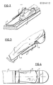
- the first embodiment of the ski boot 8 partially illustrated in FIGS. 3 and 4 comprises a sole 9, the middle part 10 of which has lateral flanges 11, 11 ′ forming on each side of the sole a ramp forming with the plane of that -ci an increasing acute angle from front to back and giving it a shape corresponding to that of the space between the jaws 4,4 'in the closed position.
- the sole 9 still has two transverse grooves 12, 13 respectively delimiting forward and backwards the middle part 10.
- the rear end of this middle part 10 also has a recess 14, located on the longitu axis dinal of the sole and which is intended to cooperate, in the service position, with a centering cone 15 fixed on the upper plate 2 of the binding, behind with respect to the lateral jaws 4,4 'and on the median longitudinal axis ski.
- the upper rim of the portion 7 of each jaw 4 may have two open notches 50, of approximately square or rectangular shape, the internal side walls of which are flared, with slopes of about 45 °, from outside to inside. These notches 50 are intended to cooperate in the service position with tabs 51 of shape corresponding to said notches. With this variant, the torsional force in the event of a fall is better transmitted to the jaws, and moreover the centering of the shoe is improved.
- the sole of the ski boot intended to be fixed by means of the binding according to the invention may have come from a workpiece with its various characteristics described above.
- the jaws 4,4' whose planar shape is conical, widening towards the rear, also comprises twisted portions 7,7 'cooperating in the service position with the sole of the shoe horizontal portions 16, 16' constituting the extensions of two arms 17,17 '.
- a rod 19 is slidably mounted longitudinally between the two arms 17, 17 'carrying the jaws 4.4', the sliding movement being centered by means of a stud 20 secured to the plate 1 cooperating with a longitudinal slot made in this rod 19.
- the front end of this rod 19 is connected to the lateral jaws 4,4 ', more particularly to their horizontal portions 16,16', by means of two pairs of rods 22,23; 22 ', 23'.
- Each pair comprises a first link 22,22 ', one end of which is articulated on the end of the rod 19, the other end of this link 22,22' being itself articulated on a second link 23,23 ', which is articulated on the horizontal portion 16,16 'of the jaw 4,4'.
- each second link 23,23 ' is in contact with a roller 27,27' fixed on the plate 1 and provided with a rotating ring so as to guide and facilitate the passage from one position to the 'other.
- the rod 19 is connected by its rear end to an elastic member constituted here by a spring 28 mounted fixed relative to the ski, longitudinally behind said rod 19.
- a lever 29 one of the ends of which cooperates with the rod 19 and the other end is connected by a link 30 to a piston 31 secured to the spring 28.
- a transverse axis 32 fixed between the corresponding ends of two rockers 29, 29 'arranged laterally parallel to one another, cooperates with the groove formed between two transverse projections 33, 33' which is provided with the rear end of the rod 19.
- each of the two rockers 29, 29 ' is connected to the piston 31 by a rods 30, 30', a transverse axis 34 being fixed to the articulation between the rockers 29, 29 'and the rods 30, 30' and a transverse axis 35 of which the ends serve as an articulation for the rods 30, 30 ′ cooperate with said piston 31.
- a guide rod 36 is moreover fixed longitudinally by one of its ends to the piston 31, passes through the spring 28 and is received by its other end freely in an adjustment nut 37, intended to adjust the elastic force of the spring 28 by screwing or unscrewing it in the wall of the housing 5.
- the transverse axis 38 connecting the bent portions of the two rockers 29 , 29 'parallel is pivoted in the par side of the housing 5.
- the linkage mechanism between the rod 19 and the elastic member 28 makes it possible, thanks to the presence of the latches 29, 29 ′, to define two stable positions corresponding to the respectively open and closed positions (FIGS. 6 and 8) of the lateral jaws 4, 4 ′ .
- the manipulation lever 6 is pivotally mounted around the ends of the axis 38 outside the housing 5, and is pierced on each side with a slightly arched opening 40 in which the ends move of the transverse axis 34 serving as an articulation between the two rockers 29, 29 'and the two links 30, 30'.
- the binding of the boot 8 on the ski 3 is obtained by placing the latter between the open side jaws 4, 4 ', so that the boot is centered by means of the centering cone 15 cooperating with the corresponding withdrawal 14 made at the 'rear of the middle part 10 of the sole 9. Then it is enough to pull on the tension lever 6 to lift it and thus cause the reversal of the position of the rockers 29,29' which causes the rearward movement of the rod 19 (see FIG. 8) and thereby the closing of the jaws 4,4 'on the middle part 10 of the sole 9 of the shoe 8.
- the design of the linkage rod 19 - elastic member 28 by means of a rocker system allowing a displacement of the support axis of the rod connected to said elastic member constitutes a lever arm modifying gradually, thus gradually decreasing the moment of force necessary to pass from the open position to the closed position and vice versa.
- the opening, respectively closing, of the jaws is therefore carried out automatically immediately after passing the balance point of the rocker (reversal point). It can be seen that the spring 28 is less compressed in the operating position (FIG. 8) than in the open position (FIG. 6), and therefore less stressed mechanically, which tends to give it greater longevity.
- the boot 8 can rotate 90 ° on each side of the ski above these jaws 4,4 'thanks to the presence of the transverse grooves 12,13 delimiting in front and in back this middle part lO.
- One of the most serious disadvantages of safety fasteners with side jaws is thus remedied, the release of the boot being ensured in any position.
- articulated links makes it possible to obtain a longer service life of the device, the friction being markedly reduced compared to known systems.
- the shoe 8 can, where appropriate, that is to say say in the event of a sudden front impact due for example to a frontal impact with a hidden obstacle, disengage directly by sliding forward.
- the second embodiment of the binding according to the invention shown in FIG. 9 comprises two base plates 101, 102 fixed on a ski 103 and between which are mounted two lateral jaws 104, 104 ′ which can be moved laterally under the action of a member elastic contained in a housing 105 fixed on the ski, the elastic member being able to be actuated for example by a lever (not shown).
- Each jaw 104, 104 ′ has a portion 106 directed from bottom to top and from the outside towards the inside and forming an acute angle increasing from front to back with the plane of the ski so as to give this portion a slightly twisted.
- the minimum angle (forward) can be on the order of about 30 °
- the maximum angle (rearward) can be on the order of about 60 °.
- the actuating device (not illustrated) of the lateral jaws 104, 104 ′ may be, for example, the same as that described above with reference to the first embodiment of the invention.
- a centering member constituted by a plate 107 having a conical imprint 108 whose tip is directed towards the front of the ski 103 and with which is intended to cooperate, in the position of service, the middle portion 109 of the sole 110 of a second embodiment of the ski boot 111 according to the invention intended to cooperate with the above safety binding.
- This sole 110 may have come from a single production part made of an appropriate plastic material and has three distinct portions connected to each other, namely an ante portion lower 112, a middle portion 09 and a heel 113, the connection between the three portions consisting of ribs 114, 114 '.
- One or the other of these portions can of course also be simply attached to the lower surface of the shoe.
- the middle part 109 of the sole 110 has upper lateral edges 115, 115 ′ forming on each side of this middle part 109 a ramp directed from the bottom up from the outside towards the inside of the latter.
- This ramp forms with the plane of the sole an increasing angle from front to back and corresponding on each side to the shape of the jaws 104, 104 'of the binding (see Figures 11, 12, 14 and 15).
- each ramp 115, 115 ' has a protruding formation 116, 116' intended to cooperate, in the service position, with a notch 106 of corresponding shape formed in the upper edge of the twisted portion 106 of the jaws 104, 104 '.
- the middle portion 109 of the sole 110 has two conical centering portions 117, 118 respectively at the front and rear ends of this middle portion 109.
- the angle of each cone respectively 117, 118 corresponds to the respective respective angles of the conical imprint 108 of the pad 107 of the safety fastening, when the middle portion 109 of the sole 110 of the ski boot 111 is in the service position between the jaws 104, 104 'of said fixing.
- the middle portion 109 of the sole 110 is clamped between the jaws 104, 104 'of the binding, the device for closing the latter having been operated.
- the jaws 104, 104 ′ are clamped on the flanges 115, 116, 115 ′, 116 ′ of said central portion 109 while the conical portions 117, 118 of the latter cooperate with the conical imprint 108 of the plate 107 of said attachment.
- a variant of the second embodiment of the binding according to the invention, illustrated in FIG. 17, differs from this in that the plate with conical imprint is replaced by four centering shoes 120, 121, 120 ', 121' , fixed on the upper face of the base plate 102 of the binding of which only one side jaw 104 is shown.
- Each shoe 120, 121, 120 'and 121' has an upper face serving as a ramp, the slope of this ramp being inclined on the one hand towards the upper surface of the base plate 102 from the outside to the inside , and on the other hand slightly inclined downwards from front to back for the front shoes 120, 120 'and from back to front for the back shoes 121, 121'.
- FIG. 17 is intended to cooperate with a sole of a ski boot, as illustrated in FIGS. 18 and 19, and which comprises three parts, respectively a front part 122, a heel 123 and a part median 124.
- this sole came from a plastic manufacturing part, the three parts constitutive being joined by conical portions 125, 126.
- the middle part 124 of the sole has lateral flanges 127, 127 ′ forming on each side of this part a ramp directed from the bottom upwards from the outside towards the inside thereof.
- This ramp forms with the plane of the sole an increasing angle from front to back and corresponding on each side to the shape of the jaws 104, 104 'of the binding (see sections of Figures 20 and 21).
- the middle portion 124 is delimited towards the front and towards the rear by two conical transverse portions 125, 126, whose faces 128, 129, 128 ', 129' inclined from bottom to top and from center of the sole towards the outside thereof correspond to the upper faces of the centering shoes 120, 121, 120 ', 121' with which they are intended to cooperate in the service position (see FIG. 22).
- the lateral flanges 127, 127 'of the central part 124 of the sole are clamped by the lateral jaws 104, 104' of the binding, and the faces 128, 129, 128 ', 129' of the portions transverse conical 125, 126 cooperate with the respective centering shoes 120, 121, 120 ', 121' of the binding.
- the middle part of the sole of the shoe according to the invention intended to be clamped by the lateral jaws of the binding, has a length less than the minimum distance between these jaws in the open position, so as to allow clearance full boot even when it is perpendicular to the axis of the ski.
- FIGS 24 and 25 illustrate an adjustable stop intended to be disposed in front of the jaws (not shown) of the second embodiment of the binding according to the invention.
- This adjustable stop comprises a stud 130 secured to the front end of a blade 131 slidably mounted longitudinally in an axial opening 132 provided between the two base plates 101, 102 of the binding.
- This blade 131 is provided with notches 133 intended to cooperate with a locking member 134 operable from the outside in order to fix the longitudinal position of the adjustable stop.
- this stop has on the one hand the advantage of making it easier for the skier to put on the binding by determining the front position against which the front end of the sole of the shoe must be placed and, on the other hand, allows the aerodynamic outer shape given to the stud 130 to deflect the snow on the sides and avoid the accumulation of it against the tip of the shoe.
- FIG. 26 illustrates a third embodiment of the binding according to the invention, in which the elastic member contained in a housing 205 fixed to the ski 203 and controlling the opening and closing of the jaws 204 having twisted portions 207b, 207c is disposed in front of the latter, that is to say in front of the tip of the ski boot 208.
- the operation of this embodiment is the same as that described with reference to the first embodiment of the binding according to the invention.
- the rocker whose axes 234, 238 are reversed with respect to the first embodiment, is actuated by the lever 206 and acts on the arms (not shown) pivoted between the base plates 201, 202 in front of the jaws 204b, 204c and As before, the jaws 204b, 204c cooperate by tightening in the service position with a ramp 211 that has the middle portion of the sole of the ski boot 208.
Landscapes
- Footwear And Its Accessory, Manufacturing Method And Apparatuses (AREA)
Priority Applications (1)
| Application Number | Priority Date | Filing Date | Title |
|---|---|---|---|
| AT83100240T ATE26072T1 (de) | 1982-01-27 | 1983-01-13 | Sicherheitsskibindung. |
Applications Claiming Priority (4)
| Application Number | Priority Date | Filing Date | Title |
|---|---|---|---|
| CH49582A CH645030A5 (fr) | 1982-01-27 | 1982-01-27 | Fixation de securite d'une chaussure sur un ski et chaussure de ski pour cette fixation. |
| CH495/82 | 1982-01-27 | ||
| CH4618/82 | 1982-07-30 | ||
| CH4618/82A CH647416A5 (en) | 1982-07-30 | 1982-07-30 | Safety binding for a boot on a ski and boot for this binding |
Publications (3)
| Publication Number | Publication Date |
|---|---|
| EP0084813A2 true EP0084813A2 (de) | 1983-08-03 |
| EP0084813A3 EP0084813A3 (en) | 1983-08-10 |
| EP0084813B1 EP0084813B1 (de) | 1987-03-25 |
Family
ID=25684736
Family Applications (1)
| Application Number | Title | Priority Date | Filing Date |
|---|---|---|---|
| EP83100240A Expired EP0084813B1 (de) | 1982-01-27 | 1983-01-13 | Sicherheitsskibindung |
Country Status (4)
| Country | Link |
|---|---|
| US (1) | US4536006A (de) |
| EP (1) | EP0084813B1 (de) |
| CA (1) | CA1207812A (de) |
| DE (2) | DE3370444D1 (de) |
Cited By (3)
| Publication number | Priority date | Publication date | Assignee | Title |
|---|---|---|---|---|
| US4657277A (en) * | 1983-11-01 | 1987-04-14 | Haldemann A.G. | Safety binding of a boot on a ski |
| EP0178375A3 (en) * | 1984-10-19 | 1987-09-02 | Haldemann A.G. | Safety binding of a boot on a ski |
| FR2909564A1 (fr) * | 2006-12-06 | 2008-06-13 | Conseil Et Tech Sarl | Dispositif de fixation d'une chaussure sur un ski |
Families Citing this family (8)
| Publication number | Priority date | Publication date | Assignee | Title |
|---|---|---|---|---|
| CH679457A5 (de) * | 1989-08-16 | 1992-02-28 | Galde Ag | |
| AT408617B (de) * | 1995-01-20 | 2002-01-25 | Burton Corp | Snowboard-schuhbindungsmechanismus |
| US6742801B1 (en) | 1995-01-20 | 2004-06-01 | The Burton Corporation | Snowboard boot binding mechanism |
| US7207591B2 (en) * | 2001-05-08 | 2007-04-24 | Rottefella As | Ski binding |
| FI124134B (en) * | 2012-07-02 | 2014-03-31 | One Way Sport Oy | Binding between a ski and a ski boot |
| WO2018170119A1 (en) | 2017-03-14 | 2018-09-20 | Stop River Development LLC | Processor-controlled snow sport boot binding |
| US11040267B2 (en) | 2017-03-14 | 2021-06-22 | Stop River Development LLC | Processor-controlled sport boot binding |
| EP3927441A4 (de) | 2019-02-25 | 2022-05-18 | Stop River Development LLC | Sicherheitsmechanismus für snowboardstiefel und bindungssystem |
Family Cites Families (13)
| Publication number | Priority date | Publication date | Assignee | Title |
|---|---|---|---|---|
| CH103005A (de) * | 1923-06-23 | 1924-01-16 | Zuber Adolf | Skibindung. |
| US1615032A (en) * | 1926-03-17 | 1927-01-18 | Palmquist Adolf John | Ski harness |
| FR1411638A (fr) * | 1963-10-17 | 1965-09-17 | Mécanisme de fixation d'un ski | |
| JPS5021900B1 (de) * | 1968-10-22 | 1975-07-26 | ||
| US3613270A (en) * | 1970-05-28 | 1971-10-19 | Nils Eie | Sole for a ski boot |
| CH604775A5 (de) * | 1974-03-15 | 1978-09-15 | Salomon & Fils F | |
| FR2282823A1 (fr) * | 1974-08-30 | 1976-03-26 | Salomon & Fils F | Chaussure de ski concue pour se deplacer librement apres declenchement dans une fixation comportant une machoire de retenue laterale |
| FR2326215A1 (fr) * | 1975-09-30 | 1977-04-29 | Salomon & Fils F | Perfectionnements aux fixations de securite pour skis |
| FR2332773A1 (fr) * | 1975-11-26 | 1977-06-24 | Salomon & Fils F | Fixation de securite pour chaussure de ski a rechaussage automatique |
| US4063752A (en) * | 1976-04-16 | 1977-12-20 | Whitaker Richard A | Ski binding having present means and detent trigger for said present means |
| FR2350854A1 (fr) * | 1976-05-14 | 1977-12-09 | Salomon & Fils F | Fixation de securite pour chaussure de ski, du type a pivot |
| US4395055A (en) * | 1978-03-20 | 1983-07-26 | Spademan Richard George | Ski release side clamping binding with hinged jaw members |
| FR2445730A1 (fr) * | 1979-01-08 | 1980-08-01 | Spademan Richard | Fixation de ski a machoires laterales et a chaussage automatique |
-
1983
- 1983-01-13 DE DE8383100240T patent/DE3370444D1/de not_active Expired
- 1983-01-13 DE DE198383100240T patent/DE84813T1/de active Pending
- 1983-01-13 EP EP83100240A patent/EP0084813B1/de not_active Expired
- 1983-01-18 US US06/458,909 patent/US4536006A/en not_active Expired - Fee Related
- 1983-01-26 CA CA000420284A patent/CA1207812A/en not_active Expired
Cited By (4)
| Publication number | Priority date | Publication date | Assignee | Title |
|---|---|---|---|---|
| US4657277A (en) * | 1983-11-01 | 1987-04-14 | Haldemann A.G. | Safety binding of a boot on a ski |
| EP0178375A3 (en) * | 1984-10-19 | 1987-09-02 | Haldemann A.G. | Safety binding of a boot on a ski |
| US4735845A (en) * | 1984-10-19 | 1988-04-05 | Haldemann Ag | Safety binding of a boot on a ski |
| FR2909564A1 (fr) * | 2006-12-06 | 2008-06-13 | Conseil Et Tech Sarl | Dispositif de fixation d'une chaussure sur un ski |
Also Published As
| Publication number | Publication date |
|---|---|
| EP0084813B1 (de) | 1987-03-25 |
| DE3370444D1 (en) | 1987-04-30 |
| CA1207812A (en) | 1986-07-15 |
| US4536006A (en) | 1985-08-20 |
| EP0084813A3 (en) | 1983-08-10 |
| DE84813T1 (de) | 1983-10-27 |
Similar Documents
| Publication | Publication Date | Title |
|---|---|---|
| EP0085313B1 (de) | Sicherheitsskibindung | |
| CH619370A5 (de) | ||
| EP0084813B1 (de) | Sicherheitsskibindung | |
| EP1935461B1 (de) | Mit einem mindestens zwischen zwei Positionen hin und her schaltbaren, beweglichen Knopf ausgestatteter Artikel | |
| EP0139815B1 (de) | Sicherheitsskibindung | |
| EP0385041A1 (de) | Befestigungsvorrichtung eines Schuhs an ein Fahrradpedal | |
| EP0692286A1 (de) | Einheit aus Skischuh und Bildung | |
| FR2662090A1 (fr) | Fixation de securite pour ski de fond. | |
| CH634754A5 (en) | Ski safety binding | |
| EP0178375B1 (de) | Sicherheitsbindung für einen Schuh auf einem Ski | |
| CH673400A5 (de) | ||
| FR2490099A1 (fr) | Dispositif pour la randonnee pour une fixation de securite de ski | |
| CH660976A5 (fr) | Fixation de securite pour ski. | |
| FR2654358A1 (fr) | Fixation de securite a plaque. | |
| EP1025882B1 (de) | Sicherheitsskibindung-Schuh-Kombination | |
| FR2501052A1 (fr) | Fixation de securite de ski | |
| EP3727619A1 (de) | Snowboardbindung mit einem in einem schalenboden durch einen drehzapfen einer lagerschale relativ zu einer basis hergstellten stiefelanschlag | |
| EP1522334B1 (de) | Schuhbindung für ein Gleit- oder Rollbrett | |
| EP0778056A1 (de) | Schuhrückhaltevorrichtung auf einem Snowboard bzw. Ski oder ähnlichem | |
| WO1998017356A1 (fr) | Dispositif de liaison entre une chaussure et un article de sport | |
| FR2657503A1 (fr) | Chaussure de ski a entree arriere. | |
| CH656542A5 (fr) | Fixation de securite pour ski. | |
| EP3492153B1 (de) | Ferseneinheit für skibindung | |
| FR3072884A1 (fr) | Butee de dispositif de fixation d'une chaussure | |
| CH491652A (fr) | Butée de sécurité avant pour fixation de ski |
Legal Events
| Date | Code | Title | Description |
|---|---|---|---|
| PUAI | Public reference made under article 153(3) epc to a published international application that has entered the european phase |
Free format text: ORIGINAL CODE: 0009012 |
|
| PUAL | Search report despatched |
Free format text: ORIGINAL CODE: 0009013 |
|
| ITF | It: translation for a ep patent filed | ||
| AK | Designated contracting states |
Designated state(s): AT CH DE FR IT LI SE |
|
| AK | Designated contracting states |
Designated state(s): AT CH DE FR IT LI SE |
|
| ITCL | It: translation for ep claims filed |
Representative=s name: ING. ENRICO LORENZONI |
|
| TCAT | At: translation of patent claims filed | ||
| DET | De: translation of patent claims | ||
| 17P | Request for examination filed |
Effective date: 19840113 |
|
| ITF | It: translation for a ep patent filed | ||
| GRAA | (expected) grant |
Free format text: ORIGINAL CODE: 0009210 |
|
| AK | Designated contracting states |
Kind code of ref document: B1 Designated state(s): AT CH DE FR IT LI SE |
|
| REF | Corresponds to: |
Ref document number: 26072 Country of ref document: AT Date of ref document: 19870415 Kind code of ref document: T |
|
| REF | Corresponds to: |
Ref document number: 3370444 Country of ref document: DE Date of ref document: 19870430 |
|
| PLBE | No opposition filed within time limit |
Free format text: ORIGINAL CODE: 0009261 |
|
| STAA | Information on the status of an ep patent application or granted ep patent |
Free format text: STATUS: NO OPPOSITION FILED WITHIN TIME LIMIT |
|
| 26N | No opposition filed | ||
| REG | Reference to a national code |
Ref country code: CH Ref legal event code: PFA Free format text: GALDE AG |
|
| ITTA | It: last paid annual fee | ||
| ITPR | It: changes in ownership of a european patent |
Owner name: CAMBIO RAGIONE SOCIALE;GALDE AG |
|
| REG | Reference to a national code |
Ref country code: FR Ref legal event code: CD |
|
| PGFP | Annual fee paid to national office [announced via postgrant information from national office to epo] |
Ref country code: AT Payment date: 19911223 Year of fee payment: 10 |
|
| PGFP | Annual fee paid to national office [announced via postgrant information from national office to epo] |
Ref country code: FR Payment date: 19920124 Year of fee payment: 10 |
|
| PGFP | Annual fee paid to national office [announced via postgrant information from national office to epo] |
Ref country code: DE Payment date: 19920305 Year of fee payment: 10 |
|
| PGFP | Annual fee paid to national office [announced via postgrant information from national office to epo] |
Ref country code: SE Payment date: 19921230 Year of fee payment: 11 |
|
| PG25 | Lapsed in a contracting state [announced via postgrant information from national office to epo] |
Ref country code: AT Effective date: 19930113 |
|
| PGFP | Annual fee paid to national office [announced via postgrant information from national office to epo] |
Ref country code: CH Payment date: 19930421 Year of fee payment: 11 |
|
| REG | Reference to a national code |
Ref country code: CH Ref legal event code: PFA Free format text: GALDE AG IN NACHLASSLIQUIDATION C/O VISURA TREUHAND-GESELLSCHAFT |
|
| PG25 | Lapsed in a contracting state [announced via postgrant information from national office to epo] |
Ref country code: FR Effective date: 19930930 |
|
| PG25 | Lapsed in a contracting state [announced via postgrant information from national office to epo] |
Ref country code: DE Effective date: 19931001 |
|
| REG | Reference to a national code |
Ref country code: FR Ref legal event code: ST |
|
| PG25 | Lapsed in a contracting state [announced via postgrant information from national office to epo] |
Ref country code: SE Effective date: 19940114 |
|
| PG25 | Lapsed in a contracting state [announced via postgrant information from national office to epo] |
Ref country code: LI Effective date: 19940131 Ref country code: CH Effective date: 19940131 |
|
| REG | Reference to a national code |
Ref country code: CH Ref legal event code: PL |
|
| EUG | Se: european patent has lapsed |
Ref document number: 83100240.7 Effective date: 19940810 |