EP0084877A1 - Verschiebbare Rohrverbindung - Google Patents
Verschiebbare Rohrverbindung Download PDFInfo
- Publication number
- EP0084877A1 EP0084877A1 EP83100563A EP83100563A EP0084877A1 EP 0084877 A1 EP0084877 A1 EP 0084877A1 EP 83100563 A EP83100563 A EP 83100563A EP 83100563 A EP83100563 A EP 83100563A EP 0084877 A1 EP0084877 A1 EP 0084877A1
- Authority
- EP
- European Patent Office
- Prior art keywords
- tubular member
- annular
- slip joint
- abutment
- inner tubular
- Prior art date
- Legal status (The legal status is an assumption and is not a legal conclusion. Google has not performed a legal analysis and makes no representation as to the accuracy of the status listed.)
- Granted
Links
- 230000033001 locomotion Effects 0.000 claims abstract description 14
- 239000000463 material Substances 0.000 claims description 13
- 238000007789 sealing Methods 0.000 claims description 12
- 230000002093 peripheral effect Effects 0.000 claims description 6
- -1 polytetrafluoroethylene Polymers 0.000 claims description 5
- 229920001343 polytetrafluoroethylene Polymers 0.000 claims description 5
- 239000004810 polytetrafluoroethylene Substances 0.000 claims description 5
- 230000006835 compression Effects 0.000 claims description 2
- 238000007906 compression Methods 0.000 claims description 2
- 239000013536 elastomeric material Substances 0.000 claims description 2
- 239000003208 petroleum Substances 0.000 abstract 1
- KAKZBPTYRLMSJV-UHFFFAOYSA-N Butadiene Chemical compound C=CC=C KAKZBPTYRLMSJV-UHFFFAOYSA-N 0.000 description 10
- 229920001971 elastomer Polymers 0.000 description 9
- 239000005060 rubber Substances 0.000 description 8
- 238000004519 manufacturing process Methods 0.000 description 7
- 239000010779 crude oil Substances 0.000 description 6
- 229920001577 copolymer Polymers 0.000 description 5
- PPBRXRYQALVLMV-UHFFFAOYSA-N Styrene Chemical compound C=CC1=CC=CC=C1 PPBRXRYQALVLMV-UHFFFAOYSA-N 0.000 description 4
- 239000012530 fluid Substances 0.000 description 4
- 238000011084 recovery Methods 0.000 description 3
- 239000003643 water by type Substances 0.000 description 3
- NLHHRLWOUZZQLW-UHFFFAOYSA-N Acrylonitrile Chemical compound C=CC#N NLHHRLWOUZZQLW-UHFFFAOYSA-N 0.000 description 2
- 244000043261 Hevea brasiliensis Species 0.000 description 2
- 229920003052 natural elastomer Polymers 0.000 description 2
- 229920001194 natural rubber Polymers 0.000 description 2
- 239000003921 oil Substances 0.000 description 2
- 229920002943 EPDM rubber Polymers 0.000 description 1
- 229920000181 Ethylene propylene rubber Polymers 0.000 description 1
- 239000005062 Polybutadiene Substances 0.000 description 1
- 150000001336 alkenes Chemical class 0.000 description 1
- 125000005250 alkyl acrylate group Chemical group 0.000 description 1
- 230000005540 biological transmission Effects 0.000 description 1
- 229920005549 butyl rubber Polymers 0.000 description 1
- 238000010276 construction Methods 0.000 description 1
- 238000006073 displacement reaction Methods 0.000 description 1
- 238000005553 drilling Methods 0.000 description 1
- 230000005489 elastic deformation Effects 0.000 description 1
- 239000000806 elastomer Substances 0.000 description 1
- HQQADJVZYDDRJT-UHFFFAOYSA-N ethene;prop-1-ene Chemical group C=C.CC=C HQQADJVZYDDRJT-UHFFFAOYSA-N 0.000 description 1
- 229920002681 hypalon Polymers 0.000 description 1
- 239000010687 lubricating oil Substances 0.000 description 1
- 230000007246 mechanism Effects 0.000 description 1
- 238000012986 modification Methods 0.000 description 1
- 230000004048 modification Effects 0.000 description 1
- 239000003129 oil well Substances 0.000 description 1
- JRZJOMJEPLMPRA-UHFFFAOYSA-N olefin Natural products CCCCCCCC=C JRZJOMJEPLMPRA-UHFFFAOYSA-N 0.000 description 1
- 229920001084 poly(chloroprene) Polymers 0.000 description 1
- 229920000058 polyacrylate Polymers 0.000 description 1
- 229920002239 polyacrylonitrile Polymers 0.000 description 1
- 229920002857 polybutadiene Polymers 0.000 description 1
- 239000013535 sea water Substances 0.000 description 1
- 229920002379 silicone rubber Polymers 0.000 description 1
- 239000000126 substance Substances 0.000 description 1
- XLYOFNOQVPJJNP-UHFFFAOYSA-N water Substances O XLYOFNOQVPJJNP-UHFFFAOYSA-N 0.000 description 1
Images


Classifications
-
- E—FIXED CONSTRUCTIONS
- E21—EARTH OR ROCK DRILLING; MINING
- E21B—EARTH OR ROCK DRILLING; OBTAINING OIL, GAS, WATER, SOLUBLE OR MELTABLE MATERIALS OR A SLURRY OF MINERALS FROM WELLS
- E21B17/00—Drilling rods or pipes; Flexible drill strings; Kellies; Drill collars; Sucker rods; Cables; Casings; Tubings
- E21B17/02—Couplings; joints
- E21B17/08—Casing joints
- E21B17/085—Riser connections
-
- B—PERFORMING OPERATIONS; TRANSPORTING
- B63—SHIPS OR OTHER WATERBORNE VESSELS; RELATED EQUIPMENT
- B63B—SHIPS OR OTHER WATERBORNE VESSELS; EQUIPMENT FOR SHIPPING
- B63B35/00—Vessels or similar floating structures specially adapted for specific purposes and not otherwise provided for
- B63B35/44—Floating buildings, stores, drilling platforms, or workshops, e.g. carrying water-oil separating devices
- B63B35/4406—Articulated towers, i.e. substantially floating structures comprising a slender tower-like hull anchored relative to the marine bed by means of a single articulation, e.g. using an articulated bearing
-
- F—MECHANICAL ENGINEERING; LIGHTING; HEATING; WEAPONS; BLASTING
- F16—ENGINEERING ELEMENTS AND UNITS; GENERAL MEASURES FOR PRODUCING AND MAINTAINING EFFECTIVE FUNCTIONING OF MACHINES OR INSTALLATIONS; THERMAL INSULATION IN GENERAL
- F16L—PIPES; JOINTS OR FITTINGS FOR PIPES; SUPPORTS FOR PIPES, CABLES OR PROTECTIVE TUBING; MEANS FOR THERMAL INSULATION IN GENERAL
- F16L27/00—Adjustable joints; Joints allowing movement
- F16L27/12—Adjustable joints; Joints allowing movement allowing substantial longitudinal adjustment or movement
- F16L27/125—Adjustable joints; Joints allowing movement allowing substantial longitudinal adjustment or movement having longitudinal and rotary movement
-
- F—MECHANICAL ENGINEERING; LIGHTING; HEATING; WEAPONS; BLASTING
- F16—ENGINEERING ELEMENTS AND UNITS; GENERAL MEASURES FOR PRODUCING AND MAINTAINING EFFECTIVE FUNCTIONING OF MACHINES OR INSTALLATIONS; THERMAL INSULATION IN GENERAL
- F16L—PIPES; JOINTS OR FITTINGS FOR PIPES; SUPPORTS FOR PIPES, CABLES OR PROTECTIVE TUBING; MEANS FOR THERMAL INSULATION IN GENERAL
- F16L27/00—Adjustable joints; Joints allowing movement
- F16L27/12—Adjustable joints; Joints allowing movement allowing substantial longitudinal adjustment or movement
- F16L27/127—Adjustable joints; Joints allowing movement allowing substantial longitudinal adjustment or movement with means for locking the longitudinal adjustment or movement in the final mounted position
- F16L27/1275—Adjustable joints; Joints allowing movement allowing substantial longitudinal adjustment or movement with means for locking the longitudinal adjustment or movement in the final mounted position by means of at least an external threaded bolt
- F16L27/12751—Adjustable joints; Joints allowing movement allowing substantial longitudinal adjustment or movement with means for locking the longitudinal adjustment or movement in the final mounted position by means of at least an external threaded bolt the threaded bolt extending longitudinally
-
- Y—GENERAL TAGGING OF NEW TECHNOLOGICAL DEVELOPMENTS; GENERAL TAGGING OF CROSS-SECTIONAL TECHNOLOGIES SPANNING OVER SEVERAL SECTIONS OF THE IPC; TECHNICAL SUBJECTS COVERED BY FORMER USPC CROSS-REFERENCE ART COLLECTIONS [XRACs] AND DIGESTS
- Y10—TECHNICAL SUBJECTS COVERED BY FORMER USPC
- Y10S—TECHNICAL SUBJECTS COVERED BY FORMER USPC CROSS-REFERENCE ART COLLECTIONS [XRACs] AND DIGESTS
- Y10S285/00—Pipe joints or couplings
- Y10S285/90—Balanced pressure
Definitions
- This invention relates to a slip joint in a riser system of an off-shore production well and more particularly to a new and improved slip joint for use in a riser system.
- a multi-line riser system which'would include among other equipment a riser base for attachment to the sea floor or ocean floor, a plurality of determinate length risers, supply pipes, universal joints for connecting the risers and mouring buoys or top support buoys along with mechanisms for use in loading the output of the production into storage vessels or ships.
- a production riser or column is a series of vertically spaced supports interconnected by universal joints with one end of the column of risers connected to a rigid or fixed base and the other end of the column of risers connected to a buoy.
- the term "production” refers to a completed well or wells and is directed to the recovery of the crude oil or gas in contrast to the drilling for the crude oil or gas.
- the base of the risers serves as the collection point for the several wells that are producing.
- the riser supports a plurality of vertically extending pipes for conveying the oil.
- the universal joint connects the ends of the adjacent risers permitting articulation therebetween and also supports the slip joints as well as swivels that interconnects the rigid pipes from one riser to rigid pipes of an adjacent riser.
- rigid flow lines such as pipes depend on the slip and swivel joints to take up all the stresses and forces that are a result of the tremendous operating conditions of wave action, and unusual weather conditions.
- Flexible hoses are not suited for marine application because of the need for large diameters for transmission of fluids and the ability to withstand high pressures.
- the slip joint of the present invention has sealing means operative under high internal pressures yet pressure balanced. Such sealing means permits the joint to sustain very large movements due to external forces while at the same time permitting oscillating motions with freedom for rotation and axial movement.
- the present invention greatly increases the space efficiency of the riser system for off-shore production fields.
- the present invention contemplates a slip joint for use in an off-shore marine environment wherein a pair of axially extending tubular members have elastic sealing means captively engaged therebetween. One of the tubular members is bonded to the elastic sealing means while the other tubular member frictionally engages and compresses the seals against a portion of the one member.
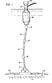
- FIG. 1 a seafloor 10 to which a base 11 is suitably anchored.
- the base 11 houses a manifold or storage means for crude oil which is pumped thereto via pipelines 12 from satellite production facilities.
- a plurality of vertically aligned risers 15 interconnected by universal joints 16 are connected to the base by an articulated joint 17.
- the uppermost universal joint 16 is connected to a buoy 18 which supports a column 19 and a housing structure 20.
- the universal joint 16 has an upper yoke member 21 and a lower yoke member 22.
- Yoke member 21 has a pair of depending leg portions 24-25 supporting a laterally extending bearing member 26 therebetween.
- Yoke member 22 has a pair of upwardly extending leg portions 27-28 supporting a laterally extending bearing member 29. With bearing members 26 and 29 interconnected at their juncture, the respective yoke members 21 and 22 are permitted to pivot at right angles to each other on their respective bearing members about axes that are normal to each other.
- Yoke member 22 has a hollow lower portion which is adapted to carry a plurality of conduits vertically therethrough. Only four conduits 30-31-32-33 are shown in Figure 2 although many more conduits are contemplated. Only four conduits are shown to provide a clearer understanding of the invention.
- Conduit 31 is connected to a conduit 41, which conduit 41 extends outwardly externally from the yoke 22 for connectipn to a swivel joint 42.
- Swivel joint 42 in turn is connected via a vertically extending conduit 43-44 to a slip joint 45, which in turn is connected via suitable conduits to a swivel joint 46, which swivel joint 46 is connected to a conduit 48 that extends through bearing member 29 into bearing member 26 for connection to a horizontally extending conduit 50.
- Slip joint 45 permits limited axial movement D etween adjacent conduits.
- Conduit 50 is connected to a swivel joint 51 thence to conduit 52 and slip joint 53.
- Slip joint 53 permits a limited axial movement between conduit 52 and a conduit 54.
- Conduit 54 is connected to one end of a swivel joint 55 which in turn is connected to a conduit 56, which conduit 56 extends into yoke member 21 for the conveyance of oil via a conduit 31' to a subsequent conduit through the risers 15 for eventual connection to a storage facilities in the buoy 18 for discharge to a waiting tanker that is moored to support column 19.
- conduits 30-32-33 in Yoke 22 are connected by conduits, swivels and slip joints to respective conduits 30'-32'-33' in yoke 21 for eventual connection through suitable conduits through the respective risers 15 to the storage facilities in the buoy 18 for subsequent or immediate unloading to a tanker that is moored to support column 19.
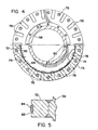
- Slip joint 53 (Fig. 3) has an inner tubular member 58 and an outer tubular member 59.
- Outer tubular member 59 has an annular or flanged end portion 60 with a plurality of circumferentially spaced bores 61 to provide means for connecting one end of such slip joint 53 to the adjacent conduit 54.
- Tubular member 59 has a plurality of stepped bores 63 and 64 extending inwardly from the flanged end portion 60. The respective bores 63 and 64 are succeedingly of larger diameter as viewed from the flange portion 60.
- the one end of inner tubular member 58 has an external diameter that permits a sliding fit with bore 64.
- the other end of tubular member 58 has an annular or flanged end portion 70 with a plurality of circumferentially spaced bores 71.
- Such flanged end portion 70 is welded to the tubular member 58 after assembly with outer tubular member 59.
- Such flanged end portion 70 provides a means for securing the slip joint 53 to the adjacent conduit 52.
- annular abutment 72 Located intermediate the flanged end portions of inner tubular member 58 is an annular abutment 72 which acts as a piston with a sleeve 73 that has its one end secured to tubular member 59.
- sleeve 73 abuttingly engages a flanged sleeve 75.
- Flanged sleeve 75, sleeve 73 and tubular member 59 have a plurality of aligned bores which receive threaded bolts 76 to provide an integral outer tubular housing within which inner tubular member 58 is adapted to reciprocate.
- the sleeve 73, flanged sleeve 75 and outer tubular member 59 cooperate with the inner tubular member 58 to define a chamber 79 within which the abutment 72 is located.
- the piston or abutment 72 is adapted to engage the annular abutment or shoulder 74 on outer tubular member 59 or annular abutment or shoulder 62 on flanged sleeve 75.
- the end face portion of outer tubular member 59 that abuttingly engages the one end of sleeve 73 has a plurality of ports 78 that vent that portion of chamber 79 that is located between piston 72 and the annular shoulder 74 to ambient or atmosphere through ports 78 while that portion of chamber 79 that is located between piston 72 and annular shoulder 74 is vented to the bore of inner tubular member 58 by means defined hereinafter.
- Chamber 79 is thus defined as the annular space located between the sleeve 73 and the outer intermediate portion of inner tubular member 58.
- the abutment or piston 72 operates within chamber 79.
- the inner tubular member 58 has a plurality of circumferentially spaced bleeder ports 80 that equalizes the pressure in chamber 79 with the pressure inside the tubular member 58 when abutment 72 is in a upwardmost position as seen in Fig. 3 exposing ports 80 to such chamber.
- the outermost circumferential edge of abutment 72 is grooved as at 82.
- a ring 84 of elastomeric material suitable for service exposure to both lubricating oils and sea water is bonded or similarly suitably secured to the outer peripheral surface of groove 82 on abutment 72.
- elastomer is defined as a substance that can be stretched at room temperature to at least twice its original length and, after having been stretched'and the stress removed, returns with force to approximately its original length in a short time. (See Glossary of Terms as prepared by ASTM Committee D-11 on Rubber and Rubber-like Materials. Published by the American Society for Testing Materials).
- the elastomeric or rubber materials that can be used include natural rubber, copolymers of butadiene and acrylonitrile, copolymers of butadiene and styrene, copolymers of butadiene and alkyl acrylates, butyl rubber, olefin rubbers such as ethylene-propylene and EPDM rubber, flurocarbon rubbers, flurosilicone rubbers, silicone rubbers, chlorosulfonated polyethylene, polyacrylates, polybutadiene, polychloroprene and the like.
- Preferred elastomeric materials include natural rubber, copolymers of butadiene/acrylonitrile and copolymers of butadiene and styrene which is often referred to as SBR.
- Such elastomeric ring or seal 84 of abutment 72 is under compression when assemblied within sleeve 78 of outer tubular member 59.
- ring 82 Prior to assembling the slip joint, such ring 82 expands radially in the normal uncompressed condition such that there is substantial clearance space to either side of ring 84 on abutment 72.
- the annular elastomeric seal 84 in the normal condition prior to assembly also extends radially outwardly a distance slightly greater than the outer periphery of groove 82 such that in the compressed condition such seal 84 is effectively sealed in the groove 82.
- annular ring or seal 85 made of a material such as from polytetrafluoroethylene is suitably secured as by bonding to the inner peripheral surface of sleeve 73 of outer tubular housing.
- elastomeric ring 84 In the compressed state of elastomeric ring 84, the outer surface thereof comes into frictional contact with the seal 85 and the edges of the groove 82 such that the groove provides support for the seal against pressure differentials.
- a second annular elastomeric ring 86 is mounted on the outer peripheral surface of inner tubular member 58 closely adjacent the flanged end of outer tubular member 59 in a suitable groove such that it operates in the same manner as ring 84.
- the other end portion of inner tubular member 58 between flange 70 and ports 80 is suitably grooved to receive a third elastomeric ring 88 that operates in the same manner as ring 84.
- the surface of inner bore 64 and inner bore surface of flanged sleeve 75 has an annular ring or seal 89 and 90 respectively of a material such as polytetrafluoroethylene secured thereto as by bonding.
- the one end portion of flanged sleeve 75 is recessed to receive a bearing 91 which has an inner surface that frictionally engages the outer surface of inner tubular member 58.
- the outer tubular member 59 adjacent to sleeve 73 is recessed to receive a bearing 92 whose inner surface frictionally engages the outer surface of one end of inner tubular member 58.
- the fluid in chamber 79 is moved inwardly into tubular member 58 via ports 80 while that portion of chamber 79 that is above the piston or abutment 72 as viewed in Fig. 3 is pressurized via ports 78 from the external fluids surrounding the slip joint 53 to provide a pressure balanced slip joint.
- the respective ring seals 84, 86 and 88 absorb axial elastic deformation.
- the ring seals 84, 86 and 88 Upon any extended axial movement between tubular members 58 and 59 the ring seals 84, 86 and 88 will move with inner tubular member 58 while their outer peripheral surfaces will slide on the respective surfaces of sleeve 73, the inner surface of bore 89 and the inner surface of the bore of flanged sleeve 75.
- the elastomeric or rubber seals 84, 86, and 88 absorb the axial thrust in the rubber until the thrust equals the frictional forces exerted by the polytetrafluoroethylene materials 89, 85 and 90. At this point, the rubber will slip on the surface of the polytetrafluoroethylene material.
Landscapes
- Engineering & Computer Science (AREA)
- Mechanical Engineering (AREA)
- General Engineering & Computer Science (AREA)
- Geology (AREA)
- Life Sciences & Earth Sciences (AREA)
- Mining & Mineral Resources (AREA)
- Fluid Mechanics (AREA)
- Structural Engineering (AREA)
- General Life Sciences & Earth Sciences (AREA)
- Geochemistry & Mineralogy (AREA)
- Physics & Mathematics (AREA)
- Architecture (AREA)
- Civil Engineering (AREA)
- Environmental & Geological Engineering (AREA)
- Chemical & Material Sciences (AREA)
- Combustion & Propulsion (AREA)
- Ocean & Marine Engineering (AREA)
- Joints Allowing Movement (AREA)
- Quick-Acting Or Multi-Walled Pipe Joints (AREA)
- Bending Of Plates, Rods, And Pipes (AREA)
- Magnetic Resonance Imaging Apparatus (AREA)
- Mechanical Coupling Of Light Guides (AREA)
Applications Claiming Priority (2)
| Application Number | Priority Date | Filing Date | Title |
|---|---|---|---|
| US06/342,447 US4437688A (en) | 1982-01-25 | 1982-01-25 | Riser pipe joint |
| US342447 | 1982-01-25 |
Publications (2)
| Publication Number | Publication Date |
|---|---|
| EP0084877A1 true EP0084877A1 (de) | 1983-08-03 |
| EP0084877B1 EP0084877B1 (de) | 1987-03-11 |
Family
ID=23341874
Family Applications (1)
| Application Number | Title | Priority Date | Filing Date |
|---|---|---|---|
| EP83100563A Expired EP0084877B1 (de) | 1982-01-25 | 1983-01-22 | Verschiebbare Rohrverbindung |
Country Status (6)
| Country | Link |
|---|---|
| US (1) | US4437688A (de) |
| EP (1) | EP0084877B1 (de) |
| JP (1) | JPS58134294A (de) |
| CA (1) | CA1192130A (de) |
| DE (1) | DE3370176D1 (de) |
| NO (1) | NO830213L (de) |
Cited By (4)
| Publication number | Priority date | Publication date | Assignee | Title |
|---|---|---|---|---|
| EP0692665A1 (de) * | 1994-07-14 | 1996-01-17 | RAFELD KUNSTSTOFFTECHNIK GmbH & Co. KG | Kompensator für Rohrleitungen |
| US7183975B2 (en) | 2002-05-15 | 2007-02-27 | Antenova Ltd. | Attaching antenna structures to electrical feed structures |
| WO2009077735A1 (en) * | 2007-12-14 | 2009-06-25 | 2H Offshore Engineering Limited | Joining metal pipes |
| US8869900B2 (en) | 2007-04-27 | 2014-10-28 | Alcoa Inc. | Method and apparatus for connecting drilling riser strings and compositions thereof |
Families Citing this family (11)
| Publication number | Priority date | Publication date | Assignee | Title |
|---|---|---|---|---|
| US4561679A (en) * | 1982-07-26 | 1985-12-31 | Exxon Production Research Co. | Seal pressure reduction system |
| JPS60104890A (ja) * | 1983-11-14 | 1985-06-10 | 本田技研工業株式会社 | 金型装置 |
| US5377763A (en) * | 1994-02-22 | 1995-01-03 | Brunswick Corporation | Riser pipe assembly for marine applications |
| US5660241A (en) * | 1995-12-20 | 1997-08-26 | Dowell, A Division Of Schlumberger Technology Corporation | Pressure compensated weight on bit shock sub for a wellbore drilling tool |
| US5746453A (en) * | 1996-06-17 | 1998-05-05 | Erc Industries, Inc. | High temperature inline expansion joint |
| US6173781B1 (en) | 1998-10-28 | 2001-01-16 | Deep Vision Llc | Slip joint intervention riser with pressure seals and method of using the same |
| US6854486B2 (en) * | 2002-05-13 | 2005-02-15 | Eaton Corporation | Fluid line assembly |
| US20050123425A1 (en) * | 2003-11-07 | 2005-06-09 | Smith Henry A.Iii | Apparatus and method for draining reservoirs |
| US7591487B2 (en) * | 2003-11-07 | 2009-09-22 | Complete Cryogenic Services, Inc. | Apparatus and method for draining reservoirs |
| US20100288505A1 (en) * | 2009-05-12 | 2010-11-18 | NAB & Associates, Inc. | Drilling riser elastic swivel for boundary layer control |
| US9328575B2 (en) | 2012-01-31 | 2016-05-03 | Weatherford Technology Holdings, Llc | Dual gradient managed pressure drilling |
Citations (4)
| Publication number | Priority date | Publication date | Assignee | Title |
|---|---|---|---|---|
| FR679492A (fr) * | 1928-10-05 | 1930-04-14 | Appareil de compensation permettant de corriger des allongements ou raccourcissements des conduites ou autres appareils | |
| DE577290C (de) * | 1930-08-12 | 1933-05-29 | Emma Antonie Fischbach Geb Wan | Stopfbuchsrohrausgleicher |
| US2373280A (en) * | 1943-07-06 | 1945-04-10 | Phillips Petroleum Co | Nonthrusting pipe expansion joint |
| GB2074683A (en) * | 1980-04-24 | 1981-11-04 | Agency Ind Science Techn | Connecting pipe pieces via a universal joint |
Family Cites Families (2)
| Publication number | Priority date | Publication date | Assignee | Title |
|---|---|---|---|---|
| CA1027607A (en) | 1975-10-07 | 1978-03-07 | Joseph K. Campbell | Expansion joint |
| US4311327A (en) | 1979-12-20 | 1982-01-19 | Exxon Production Research Company | Universal joint for multiple flowline system |
-
1982
- 1982-01-25 US US06/342,447 patent/US4437688A/en not_active Expired - Fee Related
-
1983
- 1983-01-22 EP EP83100563A patent/EP0084877B1/de not_active Expired
- 1983-01-22 DE DE8383100563T patent/DE3370176D1/de not_active Expired
- 1983-01-24 NO NO830213A patent/NO830213L/no unknown
- 1983-01-24 JP JP58008855A patent/JPS58134294A/ja active Pending
- 1983-01-24 CA CA000420106A patent/CA1192130A/en not_active Expired
Patent Citations (4)
| Publication number | Priority date | Publication date | Assignee | Title |
|---|---|---|---|---|
| FR679492A (fr) * | 1928-10-05 | 1930-04-14 | Appareil de compensation permettant de corriger des allongements ou raccourcissements des conduites ou autres appareils | |
| DE577290C (de) * | 1930-08-12 | 1933-05-29 | Emma Antonie Fischbach Geb Wan | Stopfbuchsrohrausgleicher |
| US2373280A (en) * | 1943-07-06 | 1945-04-10 | Phillips Petroleum Co | Nonthrusting pipe expansion joint |
| GB2074683A (en) * | 1980-04-24 | 1981-11-04 | Agency Ind Science Techn | Connecting pipe pieces via a universal joint |
Cited By (4)
| Publication number | Priority date | Publication date | Assignee | Title |
|---|---|---|---|---|
| EP0692665A1 (de) * | 1994-07-14 | 1996-01-17 | RAFELD KUNSTSTOFFTECHNIK GmbH & Co. KG | Kompensator für Rohrleitungen |
| US7183975B2 (en) | 2002-05-15 | 2007-02-27 | Antenova Ltd. | Attaching antenna structures to electrical feed structures |
| US8869900B2 (en) | 2007-04-27 | 2014-10-28 | Alcoa Inc. | Method and apparatus for connecting drilling riser strings and compositions thereof |
| WO2009077735A1 (en) * | 2007-12-14 | 2009-06-25 | 2H Offshore Engineering Limited | Joining metal pipes |
Also Published As
| Publication number | Publication date |
|---|---|
| DE3370176D1 (en) | 1987-04-16 |
| NO830213L (no) | 1983-07-26 |
| EP0084877B1 (de) | 1987-03-11 |
| CA1192130A (en) | 1985-08-20 |
| US4437688A (en) | 1984-03-20 |
| JPS58134294A (ja) | 1983-08-10 |
Similar Documents
| Publication | Publication Date | Title |
|---|---|---|
| US4468056A (en) | Swivel | |
| US4437688A (en) | Riser pipe joint | |
| US5133578A (en) | Flexible joint with non-diffusive barrier | |
| US4183556A (en) | Liquid filled flexible sealing joint | |
| US4068868A (en) | Flexible joints for marine risers | |
| US3997198A (en) | Swivel joint construction for pressure containing conduit | |
| US4121861A (en) | Flexible sealing joint | |
| AU743436B2 (en) | Metal seal ring for tubular joint | |
| US3981357A (en) | Marine riser | |
| EP1332312B1 (de) | Hochtemperaturendstück | |
| US4555118A (en) | Seal construction for fluid swivel joints | |
| US9845879B2 (en) | High pressure dynamic sealing arrangement | |
| US4626003A (en) | Constant motion swivel seal assembly | |
| NO832709L (no) | Tetningstrykkreduseringssystem. | |
| NO790030L (no) | Vridbar roerskjoet. | |
| JPH0567838B2 (de) | ||
| US20110155941A1 (en) | Sealing element and a coupling device and a valve device provided with such a sealing element | |
| WO2004076907A1 (en) | High temperature end fitting and method of use | |
| US4593941A (en) | Diverter flex joint | |
| RU2127846C1 (ru) | Уплотняющее устройство для вертлюга | |
| US4438957A (en) | Constant motion swivel joint | |
| GB2132297A (en) | Pipe swivel joint | |
| US4311327A (en) | Universal joint for multiple flowline system | |
| GB1582616A (en) | Liquid filled flexible conduit joint | |
| CA1040230A (en) | Flexible sealing joint |
Legal Events
| Date | Code | Title | Description |
|---|---|---|---|
| PUAI | Public reference made under article 153(3) epc to a published international application that has entered the european phase |
Free format text: ORIGINAL CODE: 0009012 |
|
| AK | Designated contracting states |
Designated state(s): DE FR GB |
|
| 17P | Request for examination filed |
Effective date: 19830722 |
|
| GRAA | (expected) grant |
Free format text: ORIGINAL CODE: 0009210 |
|
| AK | Designated contracting states |
Kind code of ref document: B1 Designated state(s): DE FR GB |
|
| REF | Corresponds to: |
Ref document number: 3370176 Country of ref document: DE Date of ref document: 19870416 |
|
| ET | Fr: translation filed | ||
| PLBE | No opposition filed within time limit |
Free format text: ORIGINAL CODE: 0009261 |
|
| STAA | Information on the status of an ep patent application or granted ep patent |
Free format text: STATUS: NO OPPOSITION FILED WITHIN TIME LIMIT |
|
| 26N | No opposition filed | ||
| GBPC | Gb: european patent ceased through non-payment of renewal fee | ||
| PG25 | Lapsed in a contracting state [announced via postgrant information from national office to epo] |
Ref country code: FR Free format text: LAPSE BECAUSE OF NON-PAYMENT OF DUE FEES Effective date: 19880930 |
|
| PG25 | Lapsed in a contracting state [announced via postgrant information from national office to epo] |
Ref country code: DE Effective date: 19881001 |
|
| PG25 | Lapsed in a contracting state [announced via postgrant information from national office to epo] |
Ref country code: GB Free format text: LAPSE BECAUSE OF NON-PAYMENT OF DUE FEES Effective date: 19881122 |
|
| REG | Reference to a national code |
Ref country code: FR Ref legal event code: ST |