EP0084878A2 - Procédé de tamisage et dispositif de mise en oeuvre - Google Patents
Procédé de tamisage et dispositif de mise en oeuvre Download PDFInfo
- Publication number
- EP0084878A2 EP0084878A2 EP83100575A EP83100575A EP0084878A2 EP 0084878 A2 EP0084878 A2 EP 0084878A2 EP 83100575 A EP83100575 A EP 83100575A EP 83100575 A EP83100575 A EP 83100575A EP 0084878 A2 EP0084878 A2 EP 0084878A2
- Authority
- EP
- European Patent Office
- Prior art keywords
- sieve
- flat springs
- vibrations
- springs
- flat
- Prior art date
- Legal status (The legal status is an assumption and is not a legal conclusion. Google has not performed a legal analysis and makes no representation as to the accuracy of the status listed.)
- Granted
Links
Images
Classifications
-
- B—PERFORMING OPERATIONS; TRANSPORTING
- B07—SEPARATING SOLIDS FROM SOLIDS; SORTING
- B07B—SEPARATING SOLIDS FROM SOLIDS BY SIEVING, SCREENING, SIFTING OR BY USING GAS CURRENTS; SEPARATING BY OTHER DRY METHODS APPLICABLE TO BULK MATERIAL, e.g. LOOSE ARTICLES FIT TO BE HANDLED LIKE BULK MATERIAL
- B07B1/00—Sieving, screening, sifting, or sorting solid materials using networks, gratings, grids, or the like
- B07B1/42—Drive mechanisms, regulating or controlling devices, or balancing devices, specially adapted for screens
-
- B—PERFORMING OPERATIONS; TRANSPORTING
- B07—SEPARATING SOLIDS FROM SOLIDS; SORTING
- B07B—SEPARATING SOLIDS FROM SOLIDS BY SIEVING, SCREENING, SIFTING OR BY USING GAS CURRENTS; SEPARATING BY OTHER DRY METHODS APPLICABLE TO BULK MATERIAL, e.g. LOOSE ARTICLES FIT TO BE HANDLED LIKE BULK MATERIAL
- B07B1/00—Sieving, screening, sifting, or sorting solid materials using networks, gratings, grids, or the like
- B07B1/28—Moving screens not otherwise provided for, e.g. swinging, reciprocating, rocking, tilting or wobbling screens
- B07B1/40—Resonant vibration screens
-
- B—PERFORMING OPERATIONS; TRANSPORTING
- B07—SEPARATING SOLIDS FROM SOLIDS; SORTING
- B07B—SEPARATING SOLIDS FROM SOLIDS BY SIEVING, SCREENING, SIFTING OR BY USING GAS CURRENTS; SEPARATING BY OTHER DRY METHODS APPLICABLE TO BULK MATERIAL, e.g. LOOSE ARTICLES FIT TO BE HANDLED LIKE BULK MATERIAL
- B07B1/00—Sieving, screening, sifting, or sorting solid materials using networks, gratings, grids, or the like
- B07B1/46—Constructional details of screens in general; Cleaning or heating of screens
- B07B1/4609—Constructional details of screens in general; Cleaning or heating of screens constructional details of screening surfaces or meshes
Definitions
- the invention relates to a sieving method in which the vibrations imparted to the sieve box are directed essentially perpendicular to the sieve plane, and to a device for carrying out this method.
- the invention therefore relates to vibrating sieves in which the sieve frame and sieve jointly carry out similar vibrations, wherein essentially fish-vibrating sieves with drive by mass force or sieves with a limited stroke with crank or eccentric drive are addressed.
- All of these drives in a horizontal or slightly inclined arrangement of the screen box, today preferably convey circular or elliptical vibrations.
- the mass of the sieve frame swings against resilient elements with a predetermined spring constant, so that the natural frequency and the critical speed can be predetermined according to known rules (see e.g. LUEGER, volume 49, page 583).
- the vibrating basic system i.e. the sieve box
- can therefore also other oscillating systems i.e. Excite resonators, the frequency of the resonance vibrations of the resonator being equal to the frequency of the natural vibrations of the basic system.
- the resonator absorbs the energy required to compensate for its own damping, i.e. a more or less large part of the energy imparted to the basic system is absorbed by the resonator.
- the sieve plate or the sieve fabric they are referred to uniformly as sieve plate in this consideration - even if there is no real training i.S. of the terminus technicus "resonance sieve", vibrating sieves are stimulated by the basic system to generate additional resonance vibrations, the amplitude of which decreases towards the clamping points of the floor in the sieve box, i.e. that the sieve tray becomes a resonator in these cases.
- This code number has a lower limit of up to approximately 1.6.
- Kv values 3 to 3.5 are generally to be used.
- restrictive conditions apply to moist or sticky, i.e. fine material exhibiting strong surface forces.
- one helps here by heating the sieve covering and evaporation of the water, the sieve generally being used as electrical resistance.
- these methods are complex and, at least not with certainty alone lead to the removal or avoidance of sieve smearing.
- the solution of the method according to the invention provides that the vibrations imparted to the sieve box below the sieve plane perpendicular to the vibration plane and perpendicular to the direction of the sieve material overflow and lying on supports fixed in the sieve box stimulate resonance vibrations, the effective amplitudes of which are directed essentially one-sided towards the sieve bottom , and that the flat springs move horizontally back and forth in addition to their vertically directed movement within a predetermined traveling distance.
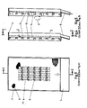
- V-shaped legs of each flat spring engage in one another in their end regions and in this case three cross bars each rest two flat springs.
- any other shaped turn deflection e.g. a pointed one is practical and possible.
- this design results in the avoidance of plug-in grain and, viewed overall, practically the maintenance of the active starting surface, ie a smaller sieve size is possible with the same output or a greater output is possible if the sieve size is maintained.
- the surface load is lower compared to the previous cleaning devices (eg tapping devices).
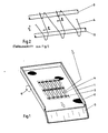
- the sieve bottom 2 forming the sieve plane is arranged in the usual manner under tension.
- 2 rods 3 are fastened below the sieve bottom at a distance from the underside of the sieve bottom 2 that takes into account the effective height of the resonance vibration amplitudes of the flat springs 4.
- the cross bars 3 thus serve to support and guide the flat springs 4. These are designed essentially in a zigzag shape, in the case of this example the two leg ends of the spring wire directed towards one another being brought into each other by a connecting cross section.
- the cross section can also be arcuate, unless a more or less sharp kinking of the legs is preferred to each other.
- the sieve frame 1 is set by a circular or elliptical oscillation drive into the required oscillation movement 6 directed in the vertical plane to the drive, which in turn excite the flat springs 4 to the resonance oscillation 7.
- the flat springs 4 are shorter than the cross bars 3 carrying them, so that, according to the difference between the light dimension between the frame parts of the screen frame 1 connected by cross bars 3 and the length of the flat springs 4, there is a traveling distance 8, over the length of which the flat springs 4 are driven Move the screening machine back and forth.
- the cross bars 3 have a diameter of 10 mm and are arranged at a distance of 36 mm from one another (commercially drawn round steel).
- the dimensioning information mentioned in this example is only a suggestion.
Landscapes
- Combined Means For Separation Of Solids (AREA)
Priority Applications (1)
| Application Number | Priority Date | Filing Date | Title |
|---|---|---|---|
| AT83100575T ATE41888T1 (de) | 1982-01-27 | 1983-01-22 | Siebverfahren und vorrichtung zur ausuebung. |
Applications Claiming Priority (2)
| Application Number | Priority Date | Filing Date | Title |
|---|---|---|---|
| DE3202528 | 1982-01-27 | ||
| DE19823202528 DE3202528A1 (de) | 1982-01-27 | 1982-01-27 | Siebverfahren und vorrichtung zur ausuebung |
Publications (3)
| Publication Number | Publication Date |
|---|---|
| EP0084878A2 true EP0084878A2 (fr) | 1983-08-03 |
| EP0084878A3 EP0084878A3 (en) | 1986-03-26 |
| EP0084878B1 EP0084878B1 (fr) | 1989-04-05 |
Family
ID=6154004
Family Applications (1)
| Application Number | Title | Priority Date | Filing Date |
|---|---|---|---|
| EP83100575A Expired EP0084878B1 (fr) | 1982-01-27 | 1983-01-22 | Procédé de tamisage et dispositif de mise en oeuvre |
Country Status (3)
| Country | Link |
|---|---|
| EP (1) | EP0084878B1 (fr) |
| AT (1) | ATE41888T1 (fr) |
| DE (1) | DE3202528A1 (fr) |
Cited By (1)
| Publication number | Priority date | Publication date | Assignee | Title |
|---|---|---|---|---|
| CN113058361A (zh) * | 2021-04-08 | 2021-07-02 | 杭州意能电力技术有限公司 | 变频式高强气流声源及其使用方法 |
Families Citing this family (1)
| Publication number | Priority date | Publication date | Assignee | Title |
|---|---|---|---|---|
| CN113289887A (zh) * | 2021-07-06 | 2021-08-24 | 西南石油大学 | 一种反共振高效隔振直线振动筛 |
Family Cites Families (6)
| Publication number | Priority date | Publication date | Assignee | Title |
|---|---|---|---|---|
| FR427986A (fr) * | 1911-03-31 | 1911-08-19 | Societe Daverio Henrici & Cie S A | Batteur pour tamis à secousses |
| US2617533A (en) * | 1948-12-17 | 1952-11-11 | Lehman | Vibrating equipment |
| US3070230A (en) * | 1958-12-12 | 1962-12-25 | Lottie J Peterson | Apparatus for separating materials |
| US3565251A (en) * | 1968-12-30 | 1971-02-23 | Blaw Knox Co | Plastic internal screen |
| DE2609683A1 (de) * | 1976-03-09 | 1977-09-15 | Juergen Hoffmann | Sieb |
| US4122006A (en) * | 1977-09-28 | 1978-10-24 | Black Clawson, Inc. | Screening apparatus |
-
1982
- 1982-01-27 DE DE19823202528 patent/DE3202528A1/de active Granted
-
1983
- 1983-01-22 EP EP83100575A patent/EP0084878B1/fr not_active Expired
- 1983-01-22 AT AT83100575T patent/ATE41888T1/de not_active IP Right Cessation
Cited By (2)
| Publication number | Priority date | Publication date | Assignee | Title |
|---|---|---|---|---|
| CN113058361A (zh) * | 2021-04-08 | 2021-07-02 | 杭州意能电力技术有限公司 | 变频式高强气流声源及其使用方法 |
| CN113058361B (zh) * | 2021-04-08 | 2022-06-17 | 杭州意能电力技术有限公司 | 变频式高强气流声源及其使用方法 |
Also Published As
| Publication number | Publication date |
|---|---|
| DE3202528C2 (fr) | 1990-09-20 |
| EP0084878B1 (fr) | 1989-04-05 |
| ATE41888T1 (de) | 1989-04-15 |
| DE3202528A1 (de) | 1983-08-04 |
| EP0084878A3 (en) | 1986-03-26 |
Similar Documents
| Publication | Publication Date | Title |
|---|---|---|
| EP1398085A1 (fr) | Crible à tamis superposés | |
| DE3102778A1 (de) | Vorrichtung fuer die schwingfestigkeitspruefung | |
| EP0150509A2 (fr) | Appareil pour la coupe de matière plastique cellulaire | |
| DE102012206347A1 (de) | Siebvorrichtung | |
| EP1120170B1 (fr) | Dispositif de tamisage | |
| DE3503125C2 (de) | Siebvorrichtung | |
| EP1480763A1 (fr) | Dispositif cribleur | |
| DE4222919A1 (de) | Siebvorrichtung und siebverfahren | |
| DE19748707C1 (de) | Schwingungstilger für einen Hubschrauber und Verwendung einer Batterie als Masse eines Schwingungstilgers | |
| DE3202528C2 (fr) | ||
| DE3034772A1 (de) | Mehrschichtige platte aus mit mindestens einem bindemittel versehenen, lignozellulosehaltigen teilchen, verfahren zu deren herstellung sowie vorrichtung zur durchfuehrung des verfahrens | |
| DE6910707U (de) | Vorrichtung zum sortieren von fischen | |
| DE69806488T2 (de) | Mit oszillierenden vibrationsdäpfungselementen ausgestatteter tennisschläger | |
| DE2133187C3 (de) | Vibrationssieb | |
| EP0099528A2 (fr) | Appareil à tamiser | |
| DE2153710C3 (de) | Abfallseparator für grüne Bohnen | |
| DE3326481C1 (de) | Siebmaschine | |
| DE2135323A1 (de) | Schwingsieb, insbesondere schwingsieb fuer die feinabsiebung | |
| DE3049144C2 (fr) | ||
| AT239164B (de) | In Resonanz schwingendes Schüttelsiebsystem | |
| DE577130C (de) | An Drahtseilen aufgehaengtes, durch unausgeglichenes Schwunggewicht bewegtes Schuettelsieb | |
| DE2731852A1 (de) | Verfahren und vorrichtung zum foerdern von fasergut o.dgl. | |
| EP3544746B1 (fr) | Utilisation d'un dispositif d'extraction de pièces de monnaie destiné à extraire des pièces de monnaie d'une charge de métaux en vrac | |
| DE1300720B (de) | Vibrations-Arbeitsvorrichtung | |
| AT5816U2 (de) | Siebvorrichtung |
Legal Events
| Date | Code | Title | Description |
|---|---|---|---|
| PUAI | Public reference made under article 153(3) epc to a published international application that has entered the european phase |
Free format text: ORIGINAL CODE: 0009012 |
|
| AK | Designated contracting states |
Designated state(s): AT BE CH FR GB IT LI LU NL SE |
|
| PUAL | Search report despatched |
Free format text: ORIGINAL CODE: 0009013 |
|
| AK | Designated contracting states |
Kind code of ref document: A3 Designated state(s): AT BE CH FR GB IT LI LU NL SE |
|
| 17P | Request for examination filed |
Effective date: 19860923 |
|
| 17Q | First examination report despatched |
Effective date: 19880310 |
|
| GRAA | (expected) grant |
Free format text: ORIGINAL CODE: 0009210 |
|
| AK | Designated contracting states |
Kind code of ref document: B1 Designated state(s): AT BE CH FR GB IT LI LU NL SE |
|
| REF | Corresponds to: |
Ref document number: 41888 Country of ref document: AT Date of ref document: 19890415 Kind code of ref document: T |
|
| ITF | It: translation for a ep patent filed | ||
| GBT | Gb: translation of ep patent filed (gb section 77(6)(a)/1977) | ||
| ET | Fr: translation filed | ||
| PG25 | Lapsed in a contracting state [announced via postgrant information from national office to epo] |
Ref country code: GB Effective date: 19900122 Ref country code: AT Effective date: 19900122 |
|
| PG25 | Lapsed in a contracting state [announced via postgrant information from national office to epo] |
Ref country code: SE Effective date: 19900123 |
|
| PG25 | Lapsed in a contracting state [announced via postgrant information from national office to epo] |
Ref country code: LU Free format text: LAPSE BECAUSE OF NON-PAYMENT OF DUE FEES Effective date: 19900131 Ref country code: LI Effective date: 19900131 Ref country code: CH Effective date: 19900131 Ref country code: BE Effective date: 19900131 |
|
| PLBE | No opposition filed within time limit |
Free format text: ORIGINAL CODE: 0009261 |
|
| STAA | Information on the status of an ep patent application or granted ep patent |
Free format text: STATUS: NO OPPOSITION FILED WITHIN TIME LIMIT |
|
| 26N | No opposition filed | ||
| BERE | Be: lapsed |
Owner name: PAUL G.M.B.H. & CO. METALLGEWEBE- U. FILTERBABRIK Effective date: 19900131 |
|
| PG25 | Lapsed in a contracting state [announced via postgrant information from national office to epo] |
Ref country code: NL Effective date: 19900801 |
|
| NLV4 | Nl: lapsed or anulled due to non-payment of the annual fee | ||
| GBPC | Gb: european patent ceased through non-payment of renewal fee | ||
| PG25 | Lapsed in a contracting state [announced via postgrant information from national office to epo] |
Ref country code: FR Effective date: 19900928 |
|
| REG | Reference to a national code |
Ref country code: CH Ref legal event code: PL |
|
| REG | Reference to a national code |
Ref country code: FR Ref legal event code: ST |
|
| EUG | Se: european patent has lapsed |
Ref document number: 83100575.6 Effective date: 19901106 |