EP0084994A2 - Detector for the localisation of an electromagnetic radiation and device for processing the signals emitted by the detector - Google Patents
Detector for the localisation of an electromagnetic radiation and device for processing the signals emitted by the detector Download PDFInfo
- Publication number
- EP0084994A2 EP0084994A2 EP83400092A EP83400092A EP0084994A2 EP 0084994 A2 EP0084994 A2 EP 0084994A2 EP 83400092 A EP83400092 A EP 83400092A EP 83400092 A EP83400092 A EP 83400092A EP 0084994 A2 EP0084994 A2 EP 0084994A2
- Authority
- EP
- European Patent Office
- Prior art keywords
- cathode
- detector
- detector according
- anode
- wire
- Prior art date
- Legal status (The legal status is an assumption and is not a legal conclusion. Google has not performed a legal analysis and makes no representation as to the accuracy of the status listed.)
- Withdrawn
Links
Images



Classifications
-
- H—ELECTRICITY
- H01—ELECTRIC ELEMENTS
- H01J—ELECTRIC DISCHARGE TUBES OR DISCHARGE LAMPS
- H01J47/00—Tubes for determining the presence, intensity, density or energy of radiation or particles
- H01J47/06—Proportional counter tubes
-
- G—PHYSICS
- G01—MEASURING; TESTING
- G01T—MEASUREMENT OF NUCLEAR OR X-RADIATION
- G01T1/00—Measuring X-radiation, gamma radiation, corpuscular radiation, or cosmic radiation
- G01T1/29—Measurement performed on radiation beams, e.g. position or section of the beam; Measurement of spatial distribution of radiation
- G01T1/2914—Measurement of spatial distribution of radiation
- G01T1/2921—Static instruments for imaging the distribution of radioactivity in one or two dimensions; Radio-isotope cameras
- G01T1/2935—Static instruments for imaging the distribution of radioactivity in one or two dimensions; Radio-isotope cameras using ionisation detectors
Definitions
- the present invention relates to a detector intended to locate the point of impact of electromagnetic radiation.
- X-ray diffraction used for the analysis of atomic structures in crystallography, metallurgy and biological chemistry, uses the spatial distribution of the secondary radiation from the sample.
- the usual method uses a point detector, and we record the number of X photons it detects during its movements
- Proportional gas meters are also known which allow each individual photon to be counted slowly and its position to be located.
- the best-developed current location meters are one-dimensional and are sensitive on a narrow rectilinear strip with a length of approximately 50 mm.
- Such a counter was produced for the first time by BORKOWSKI and KOPP (Rev. Sci. Instrum. N ° 39, page 1515, 1968).
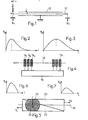
- this counter includes a resistant quartz wire 10 connected to the positive terminal of a high voltage source. This wire, which serves as an anode, is covered with a layer of carbon,
- a resistance-capacitance line with a distributed constant 12 is thus produced.
- the location of the point of impact of the photon on this line is obtained by measuring the rise times of the signals S 1 and S 2 which result therefrom and which are collected at the ends A and B of the wire 10.
- the signals S 1 and S 2 will have the appearance shown in FIGS. 2 and 3: the rise time of the signal S 1 is very low and that of the signal S 2 is longer.
- This counter which has the advantage of great simplicity, is on the other hand very fragile because the carbon layer can be easily destroyed if it is exposed to an intense beam of X-ray radiation. This counter is therefore at the mercy of a mishandling.
- FIG. 4 This counter is constituted by a central anode wire 13 made of metal, for example made of golden tungsten brought to a high potential.
- the cathode located on either side of the wire 13 is at zero potential. It consists of a plexiglass cell whose bottom is divided into parallel strips 14 1 , 14 2 ... 14 n electrically conductive.
- Each of said bands is connected to a line with distributed constants 16 also fragmented.
- a gas stream of argon and methane passes through the cell.
- the advantages of this detector are good robustness due to its metal anode wire, a counting speed resulting from the low line time constant 16 and good linearity.
- the response curve is strewn with accidents which are due to parasitic reflections at each connection socket on a cathode. This drawback makes the detector difficult to use and that is why it has not been industrialized.
- This detector always has an anode wire 18, but its cathode is made up of two pieces 20, 22 in the form of right triangles, arranged in contact according to their hypotheses, as shown in the figure 5.
- a photon falling at point C of the anode influences, on the half-cathodes 20, 22, the shaded areas 24, 26 whose surfaces of course depend on the position of C relative to the ends of the anode.
- the signals S 1 and S 2 collected on the half-cathodes have the paces shown in FIGS. 6 and 7. It can be seen that they have the same shape but different amplitudes. This variation in amplitude depends on the area influenced. We thus have a means of locating the point of impact C.
- This counter is robust and has a very flat response curve as well as good linearity, but its counting rate is limited due to its principle. Indeed, the measurement of the amplitude for a photon X can be marred by an error by the presence of another photon X arrived a few moments earlier or later.
- the object of the present invention is to remedy the aforementioned drawbacks of the counters of the signaled prior art and for this purpose proposes a counter with radiation localization which is characterized in that it essentially comprises at least one anode wire surrounded by a cathode resistive, of suitable shape, the assembly being immersed in a gaseous atmosphere which constitutes the radiation detector element.
- the cathode is constituted by a coil of metallic resistant wire, which is crossed axially by the anode wire.
- the cathode wire and the capacitance formed by the shielding which surrounds it constitute a distributed constant sensor.
- the wire is chosen with a very small diameter compared to the pitch of the winding, so that it absorbed only a negligible part of the incident radiation.
- the detector according to the invention comprises two supports in the form of half-cylinders, provided on their cylindrical wall with a pitch thread corresponding to that desired for the winding, said supports being fixed by their ends on a mounting frame which keeps them apart and parallel, with their cylindrical wall facing outwards, the cathode wire being wound around the thread of said supports and the anode wire being stretched inside the winding between two borne terminals by the carcass.
- the supports are produced from a single cylindrical rod on which a thread of pitch equal to that desired for the winding has been executed and which has been cut in two along a diametrical plane. This gives regular spacing of the turns of the winding.
- the cathode consists of a resistive tubular surface, inside which the anode wire passes axially.
- the detector makes it possible to correct a linearity error of the response curve, or to obtain a desired response curve.
- a variable pitch winding is produced. It is also possible to vary the resistance of the conductive layer of the cathode, in the case where it consists of a layer.
- the principle of the invention can be used for the production of a two-dimensional detector.
- a detector comprises two coiled cathodes, arranged at 90 ° relative to each other and nested one inside the other, a sheet of anode wires being placed at the inside the internal winding.
- the signals corresponding to the two dimensions are collected at the terminals of the cathodes.
- the two-dimensional detector comprises a wound cathode in which is nested perpendicularly an anode also wound in a flattened structure and brought to the positive potential of the high voltage. The photon is identified along one axis by the cathode and along the other axis by the anode.
- a two-dimensional detector can also be produced by using two elementary cathodes superimposed and oriented perpendicularly to one another, each of them receiving a layer of anode wires.
- the detector shown diagrammatically in FIG. 8 comprises, in principle, a cathode 30 constituted by a coil of resistant metallic wire, crossed in the axial direction by an anode wire 32 which is connected to the positive terminal of a source of high tension. It is also possible to have several anode wires inside the winding.
- the entire cathode and anode is enclosed in an enclosure 34 (FIG. 9) filled with a gaseous atmosphere 36 comprising 90% xenon or argon and 10% methane, in the case of detection of X photons.
- the detection cell shown in FIG. 10 comprises an elongated metal carcass 38 ending at its ends by portions 40, 42, profiled in I.
- two insulating supports 44, 46 in the form of half-cylinders which have a thread of small pitch on their cylindrical wall.
- the supports are therefore parallel and spaced apart by a distance equal to the thickness of said central branches.
- a metal anode wire 48 which hooks by its ends to two terminals 50, 52 carried respectively by two insulating structures 54, 56, fixed on said end portions 40, 42 of the carcass.
- One of the terminals is connected to the positive terminal of a high voltage source.
- the anode wire is stretched by spring blades 58.
- a cathode wire 60 is wound on the supports 44, 46 by passing it through the successive threads. This gives a very regular winding with tight turns.
- the ends of the cathode wire are connected to terminals 62, 64 to which the signals S 1 and S 2 induced by the anode wire 48 are collected during a photon impact. Since the cathode wire 60 completely surrounds the anode wire 48, it fully captures the influence signal induced by the latter. As a result, the signal-to-noise ratio of the preamplifiers obtained during the processing of the signals S and S 2 , is significantly higher than that obtained with known detectors. As a result, the resolution is also improved. In addition, due to the low capacity of the wound cathode, a high counting speed is obtained.
- FIG. 11 which comprises a tubular cathode 66 in which an anode wire 68 is disposed.
- the cathode can be reduced to a portion of tube 69 (FIG. 12) or even to a plate 70 (FIG. 13).
- the cathode is made of any material which may not elongate during winding, for example an alloy of chromium and nickel.
- the anode can be made of molybdenum or tungsten, possibly gilded.
- FIG. 14 represents the special resolution obtained at any point A of the cell, with a tubular cathode cell, of the type shown in FIG. 10, the detector being placed in front of a slot 50 ⁇ m wide and 8 mm height.
- the position d of the impsot point on the wire anode is plotted on the abscissa and the number of impacts N recorded at the point considered is plotted on the ordinate.
- the resolution thus obtained is between 150 and 250 ⁇ depending on the value of the filling pressure of the enclosure 36 (FIG. 9). This resolution remains practically uniform over a cell length of 45 mm.
- Figure 15 shows the energy resolution with a tubular cathode cell with a diffracted beam on a lithium fluoride crystal serving as a monochromator.
- the resolution is 15% and this value is constant at less than 1% over a cell length of 45 mm.
- the maximum counting speed is between 30,000 and 50,000 counts per second and the total electronic dead time included is around 10 ⁇ s,
- a great feature of this counter is the very small variation in spatial resolution as a function of the height of the localized beam. Between 2 and 8 mm in height, the variation is less than 10%. This is due to the great symmetry of the counter and to the fact that the incident beam is parallel to the cathode wires, as shown in FIG. 16.
- a beam 72 emitted by an X-ray tube 74 is diffracted by a sample 76.
- the reference 78 shows the shape of the diffracted beam.
- This advantage is particularly interesting because it determines the conditions of the experiment, such as the duration of the measurement, the detected flux being maximum with a large slit height.
- the cell of FIG. 10 is comparable to a line with distributed constant, as represented in FIG. 17, in which r 1 to r n are the resistances of the turns of the cathode 60 and C to C n are the capacitances of these turns relative to the shielding.
- Reference 48 represents the anode wire.
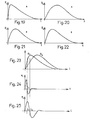
- the shape of the signals S and S 2 collected at the ends of the cathode 60 depends on the position of the impact of the photon X. Thus, if the photon arrives at A in FIG. 18, the signal S will have a very short rise time , while the signal S 2 which will have been integrated by the line between A and C will take a very long time to go up.
- the signals thus collected are respectively represented in FIGS. 19, 20.
- the signals S 1 and S 2 of FIG. 23 are shaped by double differentiation, which makes it possible to obtain the signals e 1 and e 2 represented in FIGS. 24, 25
- the difference t 2 -t 1 between the zero crossing times of the signals e 2 and e 1 represents the position information of the detected radiation.
- FIG. 26 shows the equivalent electrical diagram of a detection cell in which the shield 80 has a shape which is suitably curved to vary the distributed capacitance of the cell, with a view to correcting a linearity error in the response curve of the cell or get a desired response curve.
- the response curve can also be corrected by using a wound cathode with variable pitch 82, as shown in FIG. 27, or even by varying the resistance of the conductive layer, when the detector is thus produced.
- correction methods can be implemented to correct the parallax effect on a diffraction goniometer by giving the detector a pseudo-radius of curvature, as shown in FIG. 28.
- a beam 84 of X-rays is diffracted by a sample 86 along a goniometric circle 88 tangent to the anode wire 90 of the detector.
- the shielding 92 of the latter is given a curvature calculated so that the parallax 94 is corrected.
- the detector according to the invention can also be used for the detection of ⁇ radiation and neutrons, only the nature of the detector gas changing in both cases.
- two wound cathodes 96, 98 are fitted one into the other, so that the planes of their turns are perpendicular.
- a layer of anode wires 100 is placed inside the internal cathode 98.
- the signals corresponding to the two dimensions are collected at the terminals X, Y of the cathodes.
- the two-dimensional detector shown in FIG. 30 comprises a single wound cathode 102 and an anode 104 also wound but of very flat structure.
- the anode is inserted into the cathode so that its turns are perpendicular to those of the cathode.
- the anode is brought to the positive potential of the high voltage.
- the photon is located along an X axis by the cathode and along the Y axis by the anode.
- the anode can be replaced by a strong metallic wire folded in a ziczag.
- the two-dimensional detector of FIG. 31 comprises two elementary cells superimposed and oriented so that the turns of their respective cathode 106, 108 are perpendicular to each other. Indeed, since the photon is detected by the Compton effect, that is to say by energy loss along the path of the photon, the latter after having crossed the first cell 106 still has energy to produce a signal in the second cell 108.
- the thickness of each cell can be adjusted so that the electrical signal is equivalent in each cell. If the desired surface is large, it will be necessary to have several anode fila in each cell to ensure a sufficient electric field for the photons detected in the region of the edges.
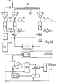
- FIGS. 32 and 33 the diagram of the electronic assembly of a device for processing the signals supplied by the detector according to the invention.
- the signal from the anode wire 48 is amplified by a preamplifier E, then shaped by the shaping device M 3 by double differentiation and integration of the signal S 3 supplied by the preamplifier E We then obtain the signal e 3 . This then passes through the energy discrimination circuit D.
- the signals from the ends of the cathode 60 are amplified by the preamplifiers P 1 and P2 which supply the signals S 1 and S 2 . These signals are shaped by double differentiation in the devices M 1 and M 2 . The zero crossing of signals e 1 and e 2 from M 1 and M 2 is detected by the comparators C 1 and C 2 . The signal from comparator C 2 is delayed by circuit R.
- the signal supplied by C 1 triggers a time-amplitude converter T / A while the signal from R stops said converter. An amplitude representing the position of the X photon detected by the counter is then obtained at the output of the latter.
- An E / B sampler-blocker allows the value contained in the T / A converter to be taken in order to release it.
- An analog-digital A / D converter converts the value contained in the sampler-blocker into a digital value which also represents the position of the photon X in the counter.
- the signal from the discrimination circuit D is received by an LC coordination logic, the output of which is connected to the sampler-blocker E / B and to the analog-digital converter A / D.
- Said logic makes it possible to synchronize the assembly, and in particular it standardizes the dead time of the system to a fixed value (from the appearance of the anode pulse until the transfer of the time-amplitude converter T / A in the E / B sampler-blocker). This has the effect of obtaining, over the entire length of the cell, an equal density of probability of treatment, for each event treated, and consequently a rectilinear response curve.
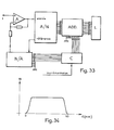
- the response curve of the counter has the shape shown in FIG. 34, on which the length of the cell is plotted on the abscissa and the number of strokes N per second, on the ordinate.
- Figure 33 explains in more detail the lower part of the diagram of Figure 32.
- the analog-digital converter A / D with successive approximations, if it allows a high speed, on the other hand presents a serious disadvantage as for the quality of the curve obtained. This is due to the unevenness of the converter steps. In an A / D converter with 4096 steps (12 bits), these faults are manifested mainly at the following crossover points: (2047, 2048), (1023, 1024), (511, 512), (255, 256) , (127, 128), etc ...
- the counter C is also connected to a binary adder ADD, so that it makes it possible to add the value which it contains to that given by the analog-digital converter A / D which it is a question of correcting.
- the output voltage of the digital / analog converter D / A is subtracted by a differential amplifier A from the signal to be measured S; it follows that the analog value subtracted from the input to the signal to be measured S is added in binary at the output of the analog-digital converter A / D by the adder ADD.
- the gain of the differential amplifier A should be adjusted so that the value subtracted is equal to the value added at the output by the adder.
Landscapes
- Physics & Mathematics (AREA)
- Health & Medical Sciences (AREA)
- Life Sciences & Earth Sciences (AREA)
- General Physics & Mathematics (AREA)
- High Energy & Nuclear Physics (AREA)
- Molecular Biology (AREA)
- Spectroscopy & Molecular Physics (AREA)
- Measurement Of Radiation (AREA)
- Nuclear Medicine (AREA)
Abstract
L'invention concerne un détecteur à localisation de rayonnement électromagnétique. Le détecteur comprend deux supports isolants (44, 46) en forme de demi-cylindres, pourvus sur leur paroi cylindrique d'un filetage de faible pas, lesdits supports étant fixés par leurs extrémités sur une carcasse de montage (40) qui les maintient écartés et parallèles, avec leur paroi cyiindrique tournée vers l'extérieur, un fil de cathode (60) étant bobiné autour du filetage desdits supports et un fil d'anode étant tendu à l'intérieur du bobinage, entre deux bornes portées par la carcasse. Application à l'analyse des structures atomiques en cristallographie, en métallurgie et en chimie biologique.The invention relates to a detector with localization of electromagnetic radiation. The detector comprises two insulating supports (44, 46) in the form of half-cylinders, provided on their cylindrical wall with a thread of small pitch, said supports being fixed by their ends on a mounting frame (40) which keeps them apart and parallel, with their cylindrical wall facing outwards, a cathode wire (60) being wound around the thread of said supports and an anode wire being stretched inside the winding, between two terminals carried by the carcass. Application to the analysis of atomic structures in crystallography, metallurgy and biological chemistry.
Description
La présente invention se rapporte à un détecteur destiné à localiser le point d'impact d'un rayonnement électromagnétique.The present invention relates to a detector intended to locate the point of impact of electromagnetic radiation.
La diffraction des rayons X, utilisée pour l'analyse des structures atomiques en cristallographie, en métallurgie et en chimie biologique, utilise la répartition dans l'espace du rayonnement secondaire issu de l'échantillon.X-ray diffraction, used for the analysis of atomic structures in crystallography, metallurgy and biological chemistry, uses the spatial distribution of the secondary radiation from the sample.
Il s'agit donc de mesurer l'intensité d'un rayonnement en un point en fonction de sa position.It is therefore a question of measuring the intensity of a radiation at a point as a function of its position.
La méthode habituellement employée utilise un détecteur ponctuel, et l'on enregistre le nombre de photons X qu'il détecte au cours de son déplacementsThe usual method uses a point detector, and we record the number of X photons it detects during its movements
Il est également possible de se servir d'un détecteur sensible sur une certaine surface et d'enregistrer le nombre de photons reçus simultanément aux différents points de cette surface : c'est ce que réalise la plaque photographique, mais son rendement est médiocre.It is also possible to use a sensitive detector on a certain surface and to record the number of photons received simultaneously at the different points on this surface: this is what the photographic plate does, but its performance is poor.
On connaît également des compteurs proportionnels à gaz qui permettent de compter chaque photon individuels lement et de localiser sa position. Les compteurs à localisation actuels les mieux au point sont unidimensionnels et sont sensibles sur une bande étroite rectiligne d'une longueur de 50 mm environ. Un tel compteur a été réalisé pour la première fois par BORKOWSKI et KOPP (Rev. Sci. Instrum. n° 39, page 1515, 1968). Comme le montre schématiquement la figure 1, ce compteur comporte un fil résistant 10 en quartz relié à la borne positive d'une source haute tension. Ce fil, qui sert d'anode, est recouvert d'une couche de carbone,Proportional gas meters are also known which allow each individual photon to be counted slowly and its position to be located. The best-developed current location meters are one-dimensional and are sensitive on a narrow rectilinear strip with a length of approximately 50 mm. Such a counter was produced for the first time by BORKOWSKI and KOPP (Rev. Sci. Instrum. N ° 39, page 1515, 1968). As shown diagrammatically in FIG. 1, this counter includes a
On réalise ainsi une ligne résistance-capacité à constante répartie 12. La localitatten du point d'impact du photon sur cette ligne est obtenue en mesurant les temps de montée des signaux S1 et S2 qui en résultent et qui sont recueillis aux extrémités A et B du fil 10. Ainsi, dans le cas où l'impact est en un point C plus proche de l'extrémité A que de l'extrémité B, les signaux S1 et S2 auront l'allure représentée sur les figures 2 et 3 : le temps de montée du signal S1 est très faible et celui du signal S2 est plus long. En réalisant une mise en forme des signaux par double différentiation on obtient l'information sur la position du rayonnement détecté, comme on l'expliquera en détail par la suite.A resistance-capacitance line with a distributed
Ce compteur, qui a l'avantage d'une grande simplicité, est par contre très fragile car la couche de carbone peut être facilement détruite si elle est exposée à un faisceau intense de rayonnement X. Ce compteur est donc à la merci d'une fausse manipulation.This counter, which has the advantage of great simplicity, is on the other hand very fragile because the carbon layer can be easily destroyed if it is exposed to an intense beam of X-ray radiation. This counter is therefore at the mercy of a mishandling.
D'autres compteurs ont depuis, été inventés, et ils tendent tous à utiliser un fil d'anode métallique, donc très robuste et, au lieu d'utiliser directement le signal reçu sur l'anode, ils utilisent l'influence électrostatique créée sur une cathode par la charge développée par avalanche au voisinage de l'anode. Dans ce type de compteur, on peut citer le détecteur à ligne à retard de GABRIEL illustré schématiquement à la figure 4. Ce compteur est constitué par un fil central d'anode 13 en métal,par exemple en tungstène doré porté à un potentiel élevé. La cathode située de part et d'autre du fil 13 est à un potentiel nul. Elle est constituée par une cellule en plexiglass dont le fond est divisé en bandes parallèles 141, 142... 14n électriquement conductrices. Chacune desdites bandes est reliée à une ligne à constantes réparties 16 également fragmentée. Un flux gazeux d'argon et de méthane traverse la cellule. Ce détecteur présente comme avantages, une bonne robustesse due à son fil d'anode métallique, une rapidité de comptage résultant de la faible constante de temps de ligne 16 et une bonne linéarité. Cependant, la courbe de réponse est parsemée d'accidents qui sont dus aux réflexions parasites à chaque prise de connexion sur une cathode, Cet inconvénient rend le détecteur difficilement utilisable et c'est pourquoi il n'a pas été industrialisé.Other meters have since been invented, and they all tend to use a metal anode wire, therefore very robust and, instead of using the signal received directly on the anode, they use the electrostatic influence created on a cathode by the charge developed by avalanche in the vicinity of the anode. In this type of counter, there may be mentioned the GABRIEL delay line detector illustrated diagrammatically in FIG. 4. This counter is constituted by a
On connait enfin le détecteur à jeu de JACQUET, Ce détecteur comporte toujours un fil d'anode 18, mais sa cathode est constituée par deux pièces 20, 22 en forme de triangles rectangles, disposés en contact selon leurs hypothénuses, comme le montre la figure 5. Un photon tombant au point C de l'anode influence, sur les demi-cathodes 20, 22, les zones grisées 24, 26 dont les surfaces dépendent bien entendu de la position de C par rapport aux extrémités de l'anode. Les signaux S1 et S2 recueillis sur les demi-cathodes ont les allures représentées sur les figures 6 et 7. On constate qu'ils ont la même forme mais des amplitudes différentes. Cette variation d'amplitude dépend de la surface influencée. On a ainsi un moyen de localiser le point d'impact C.We finally know the JACQUET game detector, This detector always has an
Ce compteur est robuste et a une courbe de réponse très plate ainsi qu'une bonne linéarité, mais son taux de comptage est limité du fait de son principe. En effet, la mesure de l'amplitude pour un photon X peut étre entachée d'une erreur par la présence d'un autre photon X arrivé quelques instants plus tôt ou plus tard.This counter is robust and has a very flat response curve as well as good linearity, but its counting rate is limited due to its principle. Indeed, the measurement of the amplitude for a photon X can be marred by an error by the presence of another photon X arrived a few moments earlier or later.
La présente invention a pour objet de remédier aux inconvénients susmentionnés des compteurs de la technique antérieure signalée et propose à cet effet un compteur à localisation de rayonnement qui se caractérise en ce qu'il comporte essentiellement au moins un fil d'anode entouré par une cathode résistive, de forme appropriée, l'ensemble étant plongé dans une atmosphère gazeuse qui constitue l'élément détecteur de rayonnement.The object of the present invention is to remedy the aforementioned drawbacks of the counters of the signaled prior art and for this purpose proposes a counter with radiation localization which is characterized in that it essentially comprises at least one anode wire surrounded by a cathode resistive, of suitable shape, the assembly being immersed in a gaseous atmosphere which constitutes the radiation detector element.
Selon un mode de réalisation avantageux de l'invention, la cathode est constituée par un bobinage en fil résistant métallique, qui est traversé axialement par le fil d'anode. Ainsi, le fil de cathode et la capacité constituée par le blindage qui l'entoure constituent un capteur à constante répartie.According to an advantageous embodiment of the invention tion, the cathode is constituted by a coil of metallic resistant wire, which is crossed axially by the anode wire. Thus, the cathode wire and the capacitance formed by the shielding which surrounds it constitute a distributed constant sensor.
Le fil est choisi avec un très faible diamètre par rapport au pas du bobinage, afin qu'il n'absorba qu'une partie négligeable du rayonnement incident.The wire is chosen with a very small diameter compared to the pitch of the winding, so that it absorbed only a negligible part of the incident radiation.
Grâce à un tel agencement, tout le signal qui est développé par influence sur la cathode est disponible pour déterminer la localisation, puisque la cathode voit le fil d'anode sous l'angle solide total. Au contraire dans les détecteurs connus précédemment signalés,qui se servent de la cathode comme capteur, seule une faible fraction du signal d'influence créé au voisinage du fil d'anode, est disponible pour déterminer la localisation. Cette fraction correspond à l'angle solide sous lequel le capteur voit le fil d'anode.Thanks to such an arrangement, all the signal which is developed by influence on the cathode is available to determine the location, since the cathode sees the anode wire under the total solid angle. In contrast, in the previously reported known detectors, which use the cathode as a sensor, only a small fraction of the influence signal created in the vicinity of the anode wire is available to determine the location. This fraction corresponds to the solid angle at which the sensor sees the anode wire.
Dans un mode de réalisation pratique, le détecteur selon l'invention comprend deux supports en forme de demi-cylindres, pourvus sur leur paroi cylindrique d'un filetage de pas correspondant à celui désiré pour le bobinage, lesdits supports étant fixés par leurs extrémités sur une carcasse de montage qui les maintient écartés et parallèles, avec leur paroi cylindrique tournée vers l'extérieur, le fil de cathode étant bobiné autour du filetage desdits supports et le fil d'anode étant tendu a l'intérieur du bobinage entre deux bornes portées par la carcasse.In a practical embodiment, the detector according to the invention comprises two supports in the form of half-cylinders, provided on their cylindrical wall with a pitch thread corresponding to that desired for the winding, said supports being fixed by their ends on a mounting frame which keeps them apart and parallel, with their cylindrical wall facing outwards, the cathode wire being wound around the thread of said supports and the anode wire being stretched inside the winding between two borne terminals by the carcass.
Les supports sont réalisés à partir d'une unique tige cylindrique sur laquelle on a exécuté un filetage de pas égal à celui désiré pour le bobinage et que l'on a coupée en deux selon un plan diamétral. On obtient de cette manière un espacement régulier des spires du bobinage.The supports are produced from a single cylindrical rod on which a thread of pitch equal to that desired for the winding has been executed and which has been cut in two along a diametrical plane. This gives regular spacing of the turns of the winding.
Selon un autre mode de réalisation de l'invention, la cathode est constituée par une surface tubulaire résistive, à l'intérieur de laquelle passe axialement le fil d'anode.According to another embodiment of the invention, the cathode consists of a resistive tubular surface, inside which the anode wire passes axially.
Selon une autre caractéristique de l'invention, le détecteur permet de corriger une erreur de linéarité de la courbe de réponse, ou d'obtenir une courbe de réponse désirée. Pour obtenir ces résultats, on peut, selon un premier procédé, faire varier la capacité répartie le long du détecteur, par exemple en donnant au blindage une forme courbe. Selon un second procédé, on réalise un bobinage à pas variable. On peut également faire varier la résistance de la couche conductrice de la cathode, dans le cas où celle-ci est constituée par une couche.According to another characteristic of the invention, the detector makes it possible to correct a linearity error of the response curve, or to obtain a desired response curve. To obtain these results, it is possible, according to a first method, to vary the capacitance distributed along the detector, for example by giving the shielding a curved shape. According to a second method, a variable pitch winding is produced. It is also possible to vary the resistance of the conductive layer of the cathode, in the case where it consists of a layer.
Le principe de l'invention peut être utilisé pour la réalisation d'un détecteur bi-dimensionnel. Dans un mode de réalisation particulier, un tel détecteur comprend deux cathodes bobinées, disposées à 90° l'une par rapport à l'autre et emboîtées l'une dans l'autre, une nappe de fils d'anodes étant placée à l'intérieur du bobinage intérieur. On recueille les signaux correspondant aux deux dimensions aux bornes des cathodes.The principle of the invention can be used for the production of a two-dimensional detector. In a particular embodiment, such a detector comprises two coiled cathodes, arranged at 90 ° relative to each other and nested one inside the other, a sheet of anode wires being placed at the inside the internal winding. The signals corresponding to the two dimensions are collected at the terminals of the cathodes.
Selon un second mode de réalisation, le détecteur bi-dimensionnel comprend une cathode bobinée dans laquelle est emboitée perpendiculairement une anode également bobinée selon une structure aplatie et portée au potentiel positif de la haute tension. Le photon est repéré suivant un axe par la cathode et suivant l'autre axe par l'anode.According to a second embodiment, the two-dimensional detector comprises a wound cathode in which is nested perpendicularly an anode also wound in a flattened structure and brought to the positive potential of the high voltage. The photon is identified along one axis by the cathode and along the other axis by the anode.
On peut encore réaliser un détecteur bi-dimensign- nel en utilisant deux cathodes élémentaires superposiez et orientées perpendiculairement l'une par rapport à l'autre, chacune d'elles recevant une nappe de fils d'anodes.A two-dimensional detector can also be produced by using two elementary cathodes superimposed and oriented perpendicularly to one another, each of them receiving a layer of anode wires.
L'invention sera mieux comprise à la lecture de la description qui va suivre de plusieurs modes de réalisation du détecteur, donnés à titre d'exemples non limitatifs en regard des dessins annexés dans lesquels
- La figure 1 est une représentation schématique du détecteur de BORKOWSKI et KOPP ;
- Les figures 2 et 3 montrent les signaux recueillis aux extrémités du fil d'anode de ce détecteur ;
- La figure 4 est le schéma du détecteur à ligne à retard de GABRIEL ;
- La figure 5 représente schématiquement le détecteur à jeu de JACQUET ;
- Les figures 6 et 7 montrent les signaux fournis par ce détecteur ;
- La figure 8 est une vue schématique du bobinage du détecteur selon l'invention ;
- La figure 9 est une vue en bout schématique du détecteur ;
- La figure 10 est une vue en perspective de la cellule de détection selon l'invention ;
- La figure 11 représente schématiquement une cathode tubulaire ;
- La figure 12 représente schématiquement une cathode en forme de portion de tube ;
- La figure 13 montre une cellule à cathode plane ;
- La figure 14 montre un diagramme de résolution spaciale obtenu avec une cellule à cathode bobinée
- La figure 15 montre un diagramme de résolution énergétique obtenu avec une cellule à cathode tubulaire
- La figure 16 représente schématiquement un montage pratique pour la détection d'un faisceau de rayons X diffracté sur un échantillon ;
- Les figures 17 et 18 représentent les circuits électriques équivalents à la cellule selon l'invention ;
- Les figures 19 et 20 montrent les signaux recueillis aux extrémités du fil de cathode lorsqu'un photon tombe sur l'une desdites extrémités ;
- Les figures 21 et 22 montrent les signaux recueillie aux extrémités du fil de cathode lorsqu'un photon tombe sensiblement au milieu de la cathode
- Les figures 23 à 25 illustrent le procédé de détermination du point d'impact du photon sur la cathode ;
- La figure 26 représente le schéma d'un détecteur à blindage de cathode courbe
- La figure 27 représente une cathode bobinée à pas variable ;
- La figure 28 illustre l'application d'un détecteur à blindage courbe pour la correction de l'effet de parallaxe sur un goniomètre de diffraction ;
- Les figures 29 à 31 représentent des vues en perspective de trois agencements de détecteurs permettant une détection bi-dimensionnelle d'un rayonnement
- La figure 32 est le schéma électronique synoptique du dispositif de traitement des signaux fournis par le détecteur ;
- La figure 33 est un montage permettant de corriger les défauts du convertisseur analogique-numérique de la figure 32 ; et
- La figure 34 représente la courbe de réponse du compteur selon l'invention.
- Figure 1 is a schematic representation of the detector of BORKOWSKI and KOPP;
- Figures 2 and 3 show the signals collected at the ends of the anode wire of this detector;
- Figure 4 is the diagram of the GABRIEL delay line detector;
- FIG. 5 schematically represents the JACQUET game detector;
- Figures 6 and 7 show the signals provided by this detector;
- FIG. 8 is a schematic view of the winding of the detector according to the invention;
- Figure 9 is a schematic end view of the detector;
- Figure 10 is a perspective view of the detection cell according to the invention;
- FIG. 11 schematically represents a tubular cathode;
- FIG. 12 schematically represents a cathode in the form of a tube portion;
- Figure 13 shows a flat cathode cell;
- Figure 14 shows a spatial resolution diagram obtained with a wound cathode cell
- Figure 15 shows an energy resolution diagram obtained with a tubular cathode cell
- FIG. 16 schematically represents a practical arrangement for the detection of a diffracted X-ray beam on a sample;
- Figures 17 and 18 show the electrical circuits equivalent to the cell according to the invention;
- Figures 19 and 20 show the signals collected at the ends of the cathode wire when a photon falls on one of said ends;
- Figures 21 and 22 show the signals collected at the ends of the cathode wire when a photon falls substantially in the middle of the cathode
- Figures 23 to 25 illustrate the method for determining the point of impact of the photon on the cathode;
- FIG. 26 represents the diagram of a detector with a curved cathode shielding
- FIG. 27 represents a cathode wound with variable pitch;
- FIG. 28 illustrates the application of a detector with curved shielding for the correction of the parallax effect on a diffraction goniometer;
- FIGS. 29 to 31 represent perspective views of three arrangements of detectors allowing two-dimensional detection of radiation
- FIG. 32 is the block diagram of the device for processing the signals supplied by the detector;
- Figure 33 is an arrangement for correcting the faults of the analog-digital converter of Figure 32; and
- FIG. 34 represents the response curve of the counter according to the invention.
Les détecteurs à localisation de rayonnement connus ayant déjà été décrits en regard des figures 1 à 7, on passera à présent directsment à la description du détecteur selon l'invention.The detectors with known radiation location having already been described with reference to FIGS. 1 to 7, we will now pass directly to the description of the detector according to the invention.
Le détecteur représenté schématiquement sur la figure 8 comprend, dans son principe, une cathode 30 constituée par un bobinage en fil métallique résistant, traversé dans le sens axial par un fil d'anode 32 qui est relié à la borne positive d'une source de haute tension. On peut également disposer plusieurs fils d'anode à l'intérieur du bobinage. L'ensemble de la cathode et de l'anode est enfermé dans une enceinte 34 (figure 9) remplie d'une atmosphère gazeuse 36 comprenant 90 % de xénon ou d'argon et 10 % de méthane, dans le cas de la détection de photons X.The detector shown diagrammatically in FIG. 8 comprises, in principle, a
Lorsqu'un photon pénètre dans l'enceinte à travers une fenêtre 37 prévue à cet effet, il perd de l'énergie par effet Compton et arrache au fur et à mesure de sa progression,plusieurs électrons primaires, chacun de ces derniers arrachant à son tour d'autres électrons. Une impulsion apparait alors sur la cathode 30 par influence de sorte que l'on peut recueillir à ses extrémités deux signaux S et S2 dont la forme ou l'amplitude dépendent du point d'impact du photon sur le fil d'anode, comme on l'expliquera par la suite.When a photon enters the enclosure through a
La cellule de détection représentée à la figure 10 comprend une carcasse métallique allongée 38 se terminant à ses extrémités par des portions 40, 42, profilées en I. De part et d'autre des branches centrales desdites portions sont fixés deux supports isolants 44, 46 en forme de demi-cylindres qui présentent sur leur paroi cylindrique un filetage de faible pas. Les supports sont donc parallèles et écartés d'une distance égale à l'épaisseur desdites branches centrales. Dans l'intervalle compris entre les supports est tendu longitudinalement un fil d'anode métallique 48 qui s'accroche par ses extrémités à deux bornes 50, 52 portées respectivement par deux structures isolantes 54, 56, fixées sur lesdites portions terminales 40, 42 de la carcasse. L'une des bornes est reliée à la borne positive d'une source haute tension. Le fil d'anode est tendu par des lames ressorts 58.The detection cell shown in FIG. 10 comprises an
Un fil de cathode 60 est bobiné sur les supports 44, 46 en le faisant passer dans les filets successifs du filetage. On obtient de cette manière un bobinage très régulier à spires serrées.A
Les extrémités du fil de cathode sont connectées à des bornes 62, 64 auxquelles on recueille les signaux S1 et S2 induits par le fil d'anode 48 lors d'un impact de photon. Etant donné que le fil de cathode 60 entoure complètement le fil d'anode 48, il capte intégralement le signal d'influence induit par ce dernier. Il en résulte que le rapport signal sur bruit des préamplim ficateurs, obtenu lors du traitement des signaux S et S2, est nettement supérieur à celui obtenu avec les détecteurs connus. La résolution est de ce fait également améliorée. De plus, en raison de la faible capacité de la cathode bobinée, on obtient une grande vitesse de comptage.The ends of the cathode wire are connected to
On obtient des performances analogues au moyen de la cellule de la figure 11, qui comprend une cathode tubulaire 66 dans laquelle est disposé un fil d'anode 68.Similar performances are obtained by means of the cell of FIG. 11, which comprises a
Dans les cas où l'on peut se contenter d'une résolution moyenne, la cathode peut se réduire à une portion de tube 69 (figure 12) ou même à une plaque 70 (figure 13).In cases where one can be satisfied with an average resolution, the cathode can be reduced to a portion of tube 69 (FIG. 12) or even to a plate 70 (FIG. 13).
On donnera à présent un exemple de réalisation de cellule du type représenté à la figure 10.An example of a cell of the type shown in FIG. 10 will now be given.

La cathode est réalisée en tout matériau susceptible de ne pas s'allonger lors du bobinage, par exemple en un alliage de chrome et de nickel. L'anode peut être réalisée en molybdène ou en tungstène, éventuellement dorés.The cathode is made of any material which may not elongate during winding, for example an alloy of chromium and nickel. The anode can be made of molybdenum or tungsten, possibly gilded.
La figure 14 représente la résolution spéciale obtenue en un point quelconque A de la cellule, avec une cellule à cathode tubulaire, du type de celle montrée à la figure 10, le détecteur étant placé devant une fente de 50 µ de largeur et de 8 mm de hauteur. La position d, du point d'impsot sur le fil d'anode est portée un abscisse et le nombre d'impacts N enregistrés au point considéré est porté en ordonnée. La résolution ainsi obtenue est comprise entre 150 et 250 µ selon la valeur de la pression de remplissage de l'enceinte 36 (figure 9). Cette résolution reste pratiquement uniforme sur une longueur de cellule de 45 mm.FIG. 14 represents the special resolution obtained at any point A of the cell, with a tubular cathode cell, of the type shown in FIG. 10, the detector being placed in front of a
La figure 15 montre la résolution en énergie avec une cellule à cathode tubulaire avec un faisceau diffracté sur un cristal de fluorure de lithium servant de monochromateur. La résolution est de 15 % et cette valeur est constante à moins de 1 % sur une longueur de cellule de 45 mm. La vitesse de comptage maximum est comprise entre 30 000 et 50 000 coups par seconde et le temps mort total électronique comprise est de l'ordre de 10 µs,Figure 15 shows the energy resolution with a tubular cathode cell with a diffracted beam on a lithium fluoride crystal serving as a monochromator. The resolution is 15% and this value is constant at less than 1% over a cell length of 45 mm. The maximum counting speed is between 30,000 and 50,000 counts per second and the total electronic dead time included is around 10 µs,
Une grande particularité de ce compteur réside dans la très faible variation de la résolution spatiale en fonction de la hauteur du faisceau localisé. Entre 2 et 8 mm de hauteur, la variation est inférieure à 10 %. Ceci est dû à la grande symétrie du compteur et au fait que le faisceau incident est parallèle aux fils de cathode, comme le montre la figure 16. Un faisceau 72 émis par un tube 74 à rayonsX est diffracté par un échantillon 76. La référence 78 montre la forme du faisceau diffracté.A great feature of this counter is the very small variation in spatial resolution as a function of the height of the localized beam. Between 2 and 8 mm in height, the variation is less than 10%. This is due to the great symmetry of the counter and to the fact that the incident beam is parallel to the cathode wires, as shown in FIG. 16. A
Cet avantage est particulièrement intéressant car il détermine les conditions de l'expérience, telles que la durée de la mesure, le flux détecté étant maximum avec une grande hauteur de fente.This advantage is particularly interesting because it determines the conditions of the experiment, such as the duration of the measurement, the detected flux being maximum with a large slit height.
On expliquera à présent le mode de détermination de la position du photon X. Tout d'abord on remarquera que la cellule de la figure 10 est assimilable à une ligne à constante répartie, telle que représentée à la figure 17, dans laquelle r1 à rn sont les résistances des spires de la cathode 60 et C à Cn sont les capacité de ces spires par rapport au blindage. La référence 48 représente le fil d'anode.The mode of determining the position of the X photon will now be explained. First of all, it will be noted that the cell of FIG. 10 is comparable to a line with distributed constant, as represented in FIG. 17, in which r 1 to r n are the resistances of the turns of the
Lorsque le nombre de spires est très grand, la somme des capacités C à Cn en parallèle tend vers l'infini, de sorte qu'elles peuvent être remplacées par une ligne 80 reliée à la terre, comme le montre la figure 18.When the number of turns is very large, the sum of the capacities C to C n in parallel tends to infinity, so that they can be replaced by a
La forme des signaux S et S2 recueillis aux extrémités de la cathode 60 dépend de la position de l'impact du photon X. Ainsi, si le photon arrive en A sur la figure 18, le signal S aura un temps de montée très faible, tandis que le signal S2 qui aura été intégré par la ligne entre A et C sera très long à monter. Les signaux ainsi recueillis sont respectivement représentés aux figures 19, 20.The shape of the signals S and S 2 collected at the ends of the
Dans le cas où le photon arrive en un point B situé sensiblement au milieu de la longueur de la cellule, les signaux S1et S2 recueillis aux extrémités de la cathode sont déformés de la même façon et ont l'allure représentée aux figures 21, 22,In the case where the photon arrives at a point B situated substantially in the middle of the length of the cell, the signals S 1 and S 2 collected at the ends of the cathode are deformed in the same way and have the shape shown in FIGS. 21 , 22,
Enfin, si le photon tombe en C situé à l'autre extrémité de la cellule,on obtiendra les mêmes signaux que dans le cas où l'impact était en A mais, les signaux S1 et S2 sont échangés.Finally, if the photon falls at C located at the other end of the cell, the same signals will be obtained as in the case where the impact was at A, but the signals S 1 and S 2 are exchanged.
Au moyen d'un système de traitement classique, on réalise la mise en forme des signaux S1 et S2 de la figure 23 par double différentiation, ce qui permet d'obtenir les signaux e1 et e2 représentés aux figures 24, 25. La différence t2-t1 entre les temps de passage à zéro des signaux e2 et e1 représente l'information de position du rayonnement détecté.By means of a conventional processing system, the signals S 1 and S 2 of FIG. 23 are shaped by double differentiation, which makes it possible to obtain the signals e 1 and e 2 represented in FIGS. 24, 25 The difference t 2 -t 1 between the zero crossing times of the signals e 2 and e 1 represents the position information of the detected radiation.
La figure 26 montre le schéma électrique équivalent d'une cellule de détection dans laquelle le blindage 80 a une forme incurvée de façon convenable pour faire varier la capacité répartie de la cellule, en vue de corriger une erreur de linéarité de la courbe de réponse de la cellule ou d'obtenir une courbe de réponse désirée.FIG. 26 shows the equivalent electrical diagram of a detection cell in which the
On peut également corriger la courbe de réponse en utilisant une cathode bobinée à pas variable 82, comme le montre la figure 27, ou encore en faisant varier la résistance de la couche conductrice, lorsque le détecteur est ainsi réalisé.The response curve can also be corrected by using a wound cathode with
Ces procédés de correction peuvent être mis en oeuvre pour corriger l'effet de parallaxe sur un goniomètre de diffraction en donnant au détecteur un pseudo- rayon de courbure, comme le montre la figure 28. Un faisceau 84 de rayons X est diffracté par un échantillon 86 suivant un cercle goniomètrique 88 tangent au fil d'anode 90 du détecteur. On donne au blindage 92 de ce dernier une courbure calculée pour que la parallaxe 94 soit corrigée.These correction methods can be implemented to correct the parallax effect on a diffraction goniometer by giving the detector a pseudo-radius of curvature, as shown in FIG. 28. A
Il va de soi que le détecteur selon l'invention peut être également utilisé pour la détection de rayonnements β et de neutrons, seule la nature du gaz détecteur changeant dans les deux cas.It goes without saying that the detector according to the invention can also be used for the detection of β radiation and neutrons, only the nature of the detector gas changing in both cases.
On décrira à présent trois réalisations partieu. lières de détecteurs bi-dimensionnels.We will now describe three part achievements. two-dimensional detector lines.
Dans le mode de réalisation de la figure 29, deux cathodes bobinées 96, 98 sont emboîtées l'une dans l'autre, de façon que les plans de leurs spires soient perpendiculaires. Une nappe de fils d'anode 100 est placée à l'intérieur de la cathode interne 98. Les signaux correspondant aux deux dimensions sont recueillis aux bornes X, Y des cathodes.In the embodiment of FIG. 29, two wound
Le détecteur bi-dimensionnel représenté sur la figure 30 comprend une seule cathode bobinée 102 et une anode 104 également bobinée mais de structure très aplatie. L'anode est insérée dans la cathode de manière que ses spires soient perpendiculaires à celles de la cathode. L'anode est portée au potentiel positif de la haute tension. Le photon est repéré suivant un axe X par la cathode et suivant l'axe Y par l'anode. En variante, l'anode peut être remplacée par un fil résistant métallique replié en zic-zag.The two-dimensional detector shown in FIG. 30 comprises a
Le détecteur bi-dimensionnel de la figure 31 comprend deux cellules élémentaires superposées et orientées de manière que les spires de leur cathode respective 106, 108 soient perpendiculaires entre elles. En effet, étant donné que la détection du photon se fait par effet Compton, c'est-à-dire par perte d'énergie le long du trajet du photon, celui-ci après avoir traversé la première cellule 106 a encore de l'énergie pour produire un signal dans la seconde cellule 108. On peut ajuster l'épaisseur de chaque cellule pour que le signal électrique soit équivalent dans chaque cellule. Si la surface désirée est importante, il sera nécessaire de disposer plusieurs fila d'anode dans chaque cellule pour assurer un champ électrique suffisant pour les photons détectés dans la région des bords.The two-dimensional detector of FIG. 31 comprises two elementary cells superimposed and oriented so that the turns of their
On décrira à présent, en regard des figures 32et 33 le schéma du montage électronique d'un dispositif de traitement des signaux fournis par le détecteur selon l'invention.We will now describe, with reference to FIGS. 32 and 33, the diagram of the electronic assembly of a device for processing the signals supplied by the detector according to the invention.
Avec référence à la figure 32, le signal issu du fil d'anode 48 est amplifié par un préamplificateur E, puis mis en forme par le dispositif de mise en forme M3 par double différentiation et intégration du signal S3 fourni par le préamplificateur E. On obtient alors le signal e3. Celui-ci passe ensuite dans le circuit de discrimination en énergie D.With reference to FIG. 32, the signal from the
Les signaux issus des extrémités de la cathode 60 sont amplifiés par les préamplificateurs P1 et P2 qui fournissent les signaux S1 et S2. Ces signaux sont mis en forme par double différentiation dans les dispositifs M1 et M2. Le passage à zéro des signaux e1 et e2 issus de M1 et M2 est detecté par les comparateurs C1 et C2. Le signal issu du comparateur C2 est retardé par le circuit R.The signals from the ends of the
Le signal fourni par C1 déclenche un convertisseur temps-amplitude T/A tandis que le signal issu de R arrête ledit convertisseur. On obtient alors en sortie de ce dernier une amplitude représentant la position du photon X détecté par le compteur.The signal supplied by C 1 triggers a time-amplitude converter T / A while the signal from R stops said converter. An amplitude representing the position of the X photon detected by the counter is then obtained at the output of the latter.
Un échantillonneur-bloqueur E/B permet de prélever la valeur contenue dans le convertisseur T/A afin de libérer celui-ci. Un convertisseur analogique-numérique A/N convertit la valeur contenue dans l'échantillonneur-bloqueur en une valeur numérique qui représente également la position du photon X dans le compteur.An E / B sampler-blocker allows the value contained in the T / A converter to be taken in order to release it. An analog-digital A / D converter converts the value contained in the sampler-blocker into a digital value which also represents the position of the photon X in the counter.
Le signal issu du circuit de discrimination D est reçu par une logique de coordination LC dont la sortie est connectée à l'échantillonneur-bloqueur E/B et au convertisseur analogique-numérique A/N. Ladite logique permet de synchroniser l'ensemble, et en particulier elle norme le temps mort du système à une valeur fixe (depuis l'apparition de l'impulsion d'anode jusqu'au transfert du convertisseur temps-amplitude T/A dans l'échantillonneur-bloqueur E/B). Ceci a pour effet d'obtenir, sur toute la longueur de la cellule, une densité de probabilité de traitement égale, pour chaque événement traité, et par conséquent une courbe de réponse rectiligne. La courbe de réponse du compteur a l'allure représentée sur la figure 34, sur laquelle la longueur de la cellule est portée en abscisses et le nombre de coups N par seconde, en ordonnées.The signal from the discrimination circuit D is received by an LC coordination logic, the output of which is connected to the sampler-blocker E / B and to the analog-digital converter A / D. Said logic makes it possible to synchronize the assembly, and in particular it standardizes the dead time of the system to a fixed value (from the appearance of the anode pulse until the transfer of the time-amplitude converter T / A in the E / B sampler-blocker). This has the effect of obtaining, over the entire length of the cell, an equal density of probability of treatment, for each event treated, and consequently a rectilinear response curve. The response curve of the counter has the shape shown in FIG. 34, on which the length of the cell is plotted on the abscissa and the number of strokes N per second, on the ordinate.
La figure 33 explicite de façon plus détaillée la partie inférieure du schéma de la figure 32. Le convertisseur analogique-numérique A/N à approximations successives, s'il permet une grande rapidité,présente par contre un grave inconvénient quant à la qualité de la courbe obtenue. Ceci est dû à l'inégalité des marches du convertisseur. Dans un convertisseur A/N à 4096 marches (12 bits), ces défauts se manifestent principalement aux points de recoupement des marches suivantes : (2047, 2048), (1023, 1024), (511, 512), (255, 256), (127, 128), etc....Figure 33 explains in more detail the lower part of the diagram of Figure 32. The analog-digital converter A / D with successive approximations, if it allows a high speed, on the other hand presents a serious disadvantage as for the quality of the curve obtained. This is due to the unevenness of the converter steps. In an A / D converter with 4096 steps (12 bits), these faults are manifested mainly at the following crossover points: (2047, 2048), (1023, 1024), (511, 512), (255, 256) , (127, 128), etc ...
Le schéma montré à la partie inférieure de la figure 32 et de façon plus détaillée à la figure 33 permet de remédier à cet inconvénient, de sorte qu'il devient possible de concilier la rapidité des convertisseurs à approximations successiveset la grande qualité de la répartition statistique des points de la courbe. On notera que ce montage n'est valable que pour un cumul statistique. Sur ce schéma, un compteur binaire C connecté à la logique de coordination LC, est incrémenté après chaque évènement. Ce compteur est relié à un convertisseur-numérique-analogique N/A, de sorte qu'il peut traduire la valeur qu'il contient en une tension proportionnelle à cette valeur.The diagram shown in the lower part of figure 32 and in more detail in figure 33 overcomes this drawback, so that it becomes possible to reconcile the speed of successive approximation converters and the high quality of the statistical distribution of the points on the curve. Note that this arrangement is only valid for a statistical cumulation. In this diagram, a binary counter C connected to the LC coordination logic, is incremented after each event. This counter is connected to a digital-to-analog D / A converter, so that it can translate the value it contains into a voltage proportional to this value.
Le compteur C est également relié à un additionneur binaire ADD, de sorte qu'il permet d'additionner la valeur qu'il contient à celle donnée par le convertisseur analogique-numérique A/N qu'il s'agit de corriger. La tension de sortie du convertisseur numérique-analogique N/A est soustraite par un amplificateur différentiel A au signal à mesurer S; il en résulte que la valeur analogique soustraite à l'entrée au signal à mesurer S est additionnée en binaire en sortie du convertisseur analogique-numérique A/N par l'additionneur ADD. Il convient d'ajuster le gain de l'amplificateur différentiel A pour que la valeur soustraite soit égale à la valeur ajoutée en sortie par l'additionneur.The counter C is also connected to a binary adder ADD, so that it makes it possible to add the value which it contains to that given by the analog-digital converter A / D which it is a question of correcting. The output voltage of the digital / analog converter D / A is subtracted by a differential amplifier A from the signal to be measured S; it follows that the analog value subtracted from the input to the signal to be measured S is added in binary at the output of the analog-digital converter A / D by the adder ADD. The gain of the differential amplifier A should be adjusted so that the value subtracted is equal to the value added at the output by the adder.
Un tel système permet pour une même amplitude de signal à mesurer d'utiliser des points de mesure différents du convertisseur analogique-numérique A/N et, par conséquent, l'histogramme réalisé ne sera entaché des erreurs dudit convertisseur que dans le rapport e, _e étant l'erreur différentielle maximum avant la correction et N le nombre de points parcourus par le compteur sur l'échelle du convertisseur analogique digital.Such a system makes it possible, for the same amplitude of the signal to be measured, to use different measurement points of the analog-digital converter A / D and, consequently, the histogram produced will not be marred by the errors of said converter except in the ratio e, _e being the maximum differential error before the correction and N the number of points traversed by the counter on the scale of the digital analog converter.
Si on prend N = 128 (compteur 7 bits) et e = 0,5 du bit le moins significatif, on aura 


Il va de soi que des modifications de détail soient apportées aux modes de réalisation décrits sans sortir pour autant du cadre de l'invention. Par exemple au lieu d'obtenir la localisation par la mesure de la phase de signaux S1, S2 on peut également atteindre ce résultat par division de la charge entre les deux extrémités de la cathode suivant la formule p = 
Claims (17)

Applications Claiming Priority (2)
| Application Number | Priority Date | Filing Date | Title |
|---|---|---|---|
| FR8201092 | 1982-01-25 | ||
| FR8201092A FR2520514B1 (en) | 1982-01-25 | 1982-01-25 | DETECTOR FOR LOCATING ELECTROMAGNETIC RADIATION AND DEVICE FOR PROCESSING SIGNALS PROVIDED BY SAID DETECTOR |
Publications (2)
| Publication Number | Publication Date |
|---|---|
| EP0084994A2 true EP0084994A2 (en) | 1983-08-03 |
| EP0084994A3 EP0084994A3 (en) | 1983-08-17 |
Family
ID=9270276
Family Applications (1)
| Application Number | Title | Priority Date | Filing Date |
|---|---|---|---|
| EP83400092A Withdrawn EP0084994A3 (en) | 1982-01-25 | 1983-01-14 | Detector for the localisation of an electromagnetic radiation and device for processing the signals emitted by the detector |
Country Status (3)
| Country | Link |
|---|---|
| US (1) | US4598204A (en) |
| EP (1) | EP0084994A3 (en) |
| FR (1) | FR2520514B1 (en) |
Families Citing this family (1)
| Publication number | Priority date | Publication date | Assignee | Title |
|---|---|---|---|---|
| FR2792772B1 (en) * | 1999-04-20 | 2001-05-18 | Commissariat Energie Atomique | IONIZATION CHAMBER, MEASUREMENT CHAIN OF ACTIVITY OF A BETA RADIATION EMITTING GAS AND METHOD OF IMPLEMENTING SAME |
Family Cites Families (6)
| Publication number | Priority date | Publication date | Assignee | Title |
|---|---|---|---|---|
| GB1179406A (en) * | 1966-02-28 | 1970-01-28 | Atomic Energy Authority Uk | Improvements in or relating to Proportional Counters |
| GB1179407A (en) * | 1966-02-28 | 1970-01-28 | Atomic Energy Authority Uk | Improvements in or relating to Geiger-Mueller Counters |
| US3517194A (en) * | 1968-10-24 | 1970-06-23 | Atomic Energy Commission | Position-sensitive radiation detector |
| US3911279A (en) * | 1973-05-17 | 1975-10-07 | Ball Brothers Res Corp | Position sensitive multiwire proportional counter with integral delay line |
| FR2255702B1 (en) * | 1973-12-21 | 1976-10-08 | Commissariat Energie Atomique | |
| DE2649192A1 (en) * | 1976-10-28 | 1978-05-11 | Braun M Gmbh | LOCATION-SENSITIVE PROPORTIONAL COUNTER TUBE |
-
1982
- 1982-01-25 FR FR8201092A patent/FR2520514B1/en not_active Expired
-
1983
- 1983-01-14 EP EP83400092A patent/EP0084994A3/en not_active Withdrawn
-
1985
- 1985-03-25 US US06/715,948 patent/US4598204A/en not_active Expired - Fee Related
Also Published As
| Publication number | Publication date |
|---|---|
| FR2520514A1 (en) | 1983-07-29 |
| FR2520514B1 (en) | 1985-10-25 |
| US4598204A (en) | 1986-07-01 |
| EP0084994A3 (en) | 1983-08-17 |
Similar Documents
| Publication | Publication Date | Title |
|---|---|---|
| EP0678896B1 (en) | Low dose ionizing X- or gamma-ray medical imaging device | |
| EP0763751B1 (en) | Method and apparatus for correcting signals in gamma photon spectroscopy | |
| Tougaard et al. | Concentration depth profiles by XPS; A new approach | |
| FR2961904A1 (en) | METHOD FOR IDENTIFYING MATERIALS FROM MULTI ENERGY X-RADIOGRAPHIES | |
| Prutton et al. | Techniques for the correction of topographical effects in scanning Auger electron microscopy | |
| EP2951565A1 (en) | Device and method for the non destructive testing of tyres by tomography | |
| EP1004040B1 (en) | Spectrometry measuring device in the field of photon gamma detection | |
| EP0851512A1 (en) | High resistivity semiconductor ionizing radiation detector | |
| EP1155341A1 (en) | Two-dimensional detector of ionising radiation and method for making same | |
| CA2122067C (en) | Method and device for calibating a set of transverse profile thickness values in flat products | |
| EP3432035A1 (en) | Method of processing a pulse generated by an ionising radiation detector | |
| EP0615274A1 (en) | Ionizing particler imaging device using a multiwire proportional chamber | |
| FR2932900A1 (en) | METHOD FOR GUIDING A VEHICLE | |
| FR2520514A1 (en) | DETECTOR FOR LOCATING ELECTROMAGNETIC RADIATION AND DEVICE FOR PROCESSING THE SIGNALS PROVIDED BY SAID DETECTOR | |
| EP0907086B1 (en) | Device for measuring the rise-time of signals containing noise, arriving from gamma- or x-ray detectors | |
| WO2014044982A2 (en) | Diffractometry-based analysis method and associated diffractometer, particularly suitable for samples comprising multiple layers of materials | |
| EP0747729A1 (en) | Method of controlling in real time the ionization dose intensity and apparatus for carrying out the method | |
| EP2787891B1 (en) | Method for the radiography of a load for performing detection | |
| FR3116619A1 (en) | SPECIMEN SUPPORT TOOLS FOR CONTROL BY TOMOGRAPHY | |
| FR2766269A1 (en) | EDD CURRENT PROBE FOR THE NON-DESTRUCTIVE CONTROL OF THE WALL OF A TUBE AND PROCESS FOR PROCESSING THE PROBE SIGNALS | |
| EP0075517B1 (en) | Device for non-destructive measuring of the thickness of the wall of a hollow workpiece | |
| FR3058522A1 (en) | CONTROL HEAD FOR CURRENT CURRENT SENSORS | |
| FR2522415A1 (en) | PROPORTIONAL DETECTOR OF IONIZING RADIATION FOR TWO DIMENSIONAL LOCATION | |
| EP2737339B1 (en) | Processing device and method for the spectrometric measurement of a photon flux | |
| EP3749981A1 (en) | System for characterizing a beam of charged particles and machine for producing a beam of charged particles comprising such a system |
Legal Events
| Date | Code | Title | Description |
|---|---|---|---|
| PUAI | Public reference made under article 153(3) epc to a published international application that has entered the european phase |
Free format text: ORIGINAL CODE: 0009012 |
|
| PUAL | Search report despatched |
Free format text: ORIGINAL CODE: 0009013 |
|
| AK | Designated contracting states |
Designated state(s): AT CH DE GB IT LI NL |
|
| AK | Designated contracting states |
Designated state(s): AT CH DE GB IT LI NL |
|
| 17P | Request for examination filed |
Effective date: 19831231 |
|
| 17Q | First examination report despatched |
Effective date: 19860630 |
|
| STAA | Information on the status of an ep patent application or granted ep patent |
Free format text: STATUS: THE APPLICATION HAS BEEN WITHDRAWN |
|
| 18W | Application withdrawn |
Withdrawal date: 19860915 |