EP0085174B1 - Dispositif pour la reconnaissance d'objets éloignés émettant des radiations électromagnétiques - Google Patents
Dispositif pour la reconnaissance d'objets éloignés émettant des radiations électromagnétiques Download PDFInfo
- Publication number
- EP0085174B1 EP0085174B1 EP82111730A EP82111730A EP0085174B1 EP 0085174 B1 EP0085174 B1 EP 0085174B1 EP 82111730 A EP82111730 A EP 82111730A EP 82111730 A EP82111730 A EP 82111730A EP 0085174 B1 EP0085174 B1 EP 0085174B1
- Authority
- EP
- European Patent Office
- Prior art keywords
- detectors
- signals
- detector
- objects
- correlation values
- Prior art date
- Legal status (The legal status is an assumption and is not a legal conclusion. Google has not performed a legal analysis and makes no representation as to the accuracy of the status listed.)
- Expired
Links
- 230000005670 electromagnetic radiation Effects 0.000 title 1
- 238000005259 measurement Methods 0.000 claims description 8
- 230000005855 radiation Effects 0.000 claims description 6
- 238000003491 array Methods 0.000 claims 1
- 230000003287 optical effect Effects 0.000 description 19
- 241000219739 Lens Species 0.000 description 7
- 238000001514 detection method Methods 0.000 description 6
- 238000005311 autocorrelation function Methods 0.000 description 5
- 238000012634 optical imaging Methods 0.000 description 5
- 238000000034 method Methods 0.000 description 4
- 210000002435 tendon Anatomy 0.000 description 4
- 230000004304 visual acuity Effects 0.000 description 4
- 230000002596 correlated effect Effects 0.000 description 3
- 230000000875 corresponding effect Effects 0.000 description 2
- 238000006073 displacement reaction Methods 0.000 description 2
- 230000000694 effects Effects 0.000 description 2
- 238000011156 evaluation Methods 0.000 description 2
- 238000003384 imaging method Methods 0.000 description 2
- 238000005305 interferometry Methods 0.000 description 2
- 241000196324 Embryophyta Species 0.000 description 1
- 240000004322 Lens culinaris Species 0.000 description 1
- 239000011248 coating agent Substances 0.000 description 1
- 238000000576 coating method Methods 0.000 description 1
- 230000004456 color vision Effects 0.000 description 1
- 238000007796 conventional method Methods 0.000 description 1
- 230000001419 dependent effect Effects 0.000 description 1
- 230000008030 elimination Effects 0.000 description 1
- 238000003379 elimination reaction Methods 0.000 description 1
- ZINJLDJMHCUBIP-UHFFFAOYSA-N ethametsulfuron-methyl Chemical compound CCOC1=NC(NC)=NC(NC(=O)NS(=O)(=O)C=2C(=CC=CC=2)C(=O)OC)=N1 ZINJLDJMHCUBIP-UHFFFAOYSA-N 0.000 description 1
- 230000004438 eyesight Effects 0.000 description 1
- 230000010354 integration Effects 0.000 description 1
- 238000012545 processing Methods 0.000 description 1
- 230000003595 spectral effect Effects 0.000 description 1
- 238000001228 spectrum Methods 0.000 description 1
- 230000036962 time dependent Effects 0.000 description 1
- 238000012549 training Methods 0.000 description 1
Images


Classifications
-
- G—PHYSICS
- G01—MEASURING; TESTING
- G01J—MEASUREMENT OF INTENSITY, VELOCITY, SPECTRAL CONTENT, POLARISATION, PHASE OR PULSE CHARACTERISTICS OF INFRARED, VISIBLE OR ULTRAVIOLET LIGHT; COLORIMETRY; RADIATION PYROMETRY
- G01J9/00—Measuring optical phase difference; Determining degree of coherence; Measuring optical wavelength
- G01J9/02—Measuring optical phase difference; Determining degree of coherence; Measuring optical wavelength by interferometric methods
-
- G—PHYSICS
- G02—OPTICS
- G02B—OPTICAL ELEMENTS, SYSTEMS OR APPARATUS
- G02B27/00—Optical systems or apparatus not provided for by any of the groups G02B1/00 - G02B26/00, G02B30/00
- G02B27/58—Optics for apodization or superresolution; Optical synthetic aperture systems
Definitions
- Known devices for automatic object recognition contain a grid of detectors, on which an optical image of an optical field of a field of view containing the object is generated by an optical imaging system.
- the detector signals form a pattern of gray or color values that corresponds to this optical image.
- a computer compares this pattern with stored, similar patterns of known objects. As a result, the observed object can be assigned to a certain class of objects, that is to say "recognized”.
- optical imaging system depends on its aperture.
- Optical systems with a very large aperture are very complex. Their performance is also affected by, and ultimately limited by, thermal influences and problems of mechanical stability.
- Another factor that makes the detection of distant objects difficult is the blurring that results from uncontrolled movements of the optical imaging system (wobbling) and uncontrollable refractions of the light rays in the generally turbulent atmosphere (flickering).
- a device known as "intensity interferometer” for determining the diameter of fixed stars is known (R. Hanbury Brown “The Intensity Interferometer, its Application to Astronomy", Verlag Taylor and Francis Ltd., London).
- Two photoelectric detectors, each of which is exposed to the radiation of this fixed star via a concave mirror directed onto the fixed star, are connected to a correlator.
- the correlation of the signals supplied by the two detectors is measured. It depends on the coherence of the radiation falling on the two detectors.
- the angular diameter of the fixed star can be calculated from the course of this correlation as a function of the distance between the detectors, assuming that the fixed star appears as a circular disk. Objects whose intensity distribution cannot be assumed to be a circular disk (e.g. unknown objects) could only be detected very partially with such an arrangement.
- the invention has for its object to provide a device for the detection of very distant, practically no longer resolvable with conventional optical means, electromagnetically incoherent (e.g. thermal) radiating objects, the apparent fluctuations of the object due to mechanical or air refraction compared to the Device is not affected.
- electromagnetically incoherent e.g. thermal
- the "pattern” is therefore not the optical image of the object, but a pattern that results from the correlations of different detector signal pairs.
- This pattern which does not correspond to an optical image of the object, but as shown below.
- Points of the Fourier transform of the autocorrelation function of the image brightness can also serve to assign the observed object to a certain class of objects by comparison with corresponding patterns of known objects and to “recognize” them in this sense.
- the pattern thus obtained has the further advantage that it is invariant against relative movements of the object and the device, provided that the object remains in the field of view of the device.
- Object detection is therefore not affected by fluctuations in the device or by the refraction of light, which only cause the object to appear to move within the field of vision.
- With an appropriate arrangement of the detectors a high resolution can be achieved, which would otherwise only be achievable with optical devices with a very large diameter of the aperture. The requirements for the mechanical precision of the arrangement are nevertheless relatively low.
- Embodiments of the invention are the subject of the dependent claims.
- the described device of detectors and correlators is also referred to below as an "electronic lens" because it allows essential functions of a lens of very high resolution to be achieved with purely electronic means.
- the "electronic lens" of Fig. 1 contains five detectors D 1 , D 2 , D 3 , D 4 and D 5 , all of the like or the like via reflectors. Receive radiation from an object to be recognized.
- the detectors D 1 , D 2 , D 3 , D 4 and D 5 are arranged in a regular arrangement on a circle, so that they form the corners of an imaginary pentagon, indicated by dashed lines in FIG. 1.
- This results in ten correlation signals Q ij which form a "pattern" of correlation values that is fed to a computer.
- the computer compares the pattern with corresponding patterns of known objects and thus carries out an assignment of the observed object to a specific class of objects, for example specific aircraft at a specific distance from a specific aspect angle, which as a result, as indicated in FIG. 1, is issued.
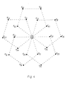
- Fig. 4 shows an illustrative interpretation of the "pattern". If, as shown in FIG. 4, points K ij are assigned to the pairs (D i , D j ) of detectors from FIG. 1, with point K 41 being assigned the same signal as point K 14 , for example, this results in Interpolation points of the Fourier transforms ⁇ (u, v) of the autocorrelation function of the intensity distribution I (x, y) in the object plane.
- FIG. 2 shows the object plane F o with the coordinates x and y and the detector plane F d with the coordinates X and Y.
- the object plane F o there is an object which provides an intensity distribution I (x, y).
- the detector plane there are detectors at points P 1 , P 2 ...., P 5 ....
- the distance between object plane F o and detector plane F d is R.
- the invention is based on the following physical principles:
- the essential measured variables of the method are the amounts of the mutually complex degrees of coherence ("Principles of Optics” 2nd ed. M. Born and E. Wolf. Pergamon Press, London 1964)
- (X i , Y,) and (X j , Y j ) are the coordinates of the points P i and P j with respect to a Cartesian coordinate system in the detector plane F d originating from D.
- x, y are the coordinates of a point in the object plane F o with respect to a Cartesian coordinate system originating in O, the axes of which lie parallel to the coordinate axes of the system in the detector plane.
- R is the distance between the object and detector levels.
- k 2 ⁇ / ⁇ denotes the length of the wave vector, ⁇ the wavelength of the light used, essentially assumed to be monochromatic.
- the integral in the numerator of equation (1) essentially represents the Fourier transform I (u, v) of I (x, y).
- ⁇ (P j , Pj) is to place detectors at the points P i , P j and to correlate the resulting photocurrents. This is the idea of intensity interferometry according to Hanbury Brown and Twiss, which is characterized by very low susceptibility to interference with almost unlimited resolution due to the loss of optical paths.
- a "dense occupation" of the detector level is not necessary for this, as the following example shows: Just think of the points P on a circular line with diameter d "dense" with detectors and for the time being only correlate the detector pairs at the end points P ,, P j of a family of parallel tendons, cf. Fig. 3. Since apparently there are all detector distances between O and d and because the parallel offset of the correlated pairs is without coating, these detector pairs provide the same measured values as the total of all detector pairs that are on the largest chord, ie on the circle diameter parallel to that picked out tendon array, could accommodate.
- the support points can partially collapse, ie the relevant function value is measured several times.
- An example would be six detectors on the corners of a regular hexagon.
- Such degeneracies allow an automatic adjustment of the detectors, which are e.g. can be modified by a computer until all the correlation values that occur multiple times actually turn out to be the same size within predetermined tolerances. It depends on the intended use of the device whether this advantage outweighs the disadvantage of a smaller number of different measured values or even overcompensates it.
- FIG. 4 shows, as an example, the reference points (u, v) (in arbitrary units) for which an arrangement of five detectors according to FIG. 1 would deliver the functional values ⁇ (u, v).
- the information content of such a measurement is certainly less than that of a conventional, monochromatic image of the same resolution; Because of the high resolving power of the device, which essentially corresponds to the resolving power of a lens of comparable diameter, the lesser information can often still be obtained in situations where a conventional image can no longer be produced. If the object is known, the lesser information is usually sufficient to determine its distance.
- an object If an object is unknown, it can be classified according to object classes, whereby the distinguishable classes are to be defined by the current method.
- Objects in the core area of application of the proposed method namely in situations beyond the practical use of the required lens or mirror system, would optically only form one class, the "class of non-resolvable point objects".
- the invention allows further classifications within this otherwise no longer resolvable class of objects.
- the invention can also be used in areas where optical imaging devices are basically available, but e.g. cannot be used due to lack of robustness or stability, e.g. a high-resolution telescope on board a helicopter. This gain results from the elimination of the interference-prone optical light paths in systems based on the wave interference.
- Equation (4) states that such a blurring, be it as a result of a real natural movement of the object, be it as a result of an apparent movement due to a lack of stability of the optical axis, or as a result of both at the same time, is physically not possible with the new method of obtaining information.
- the object must be permanently in the field of view of the system, but not on the optical axis. This is important because the training device that provides the tracking will usually have a lower resolution and therefore would not be able to guide the optical axis with the accuracy that would be required for conventional, higher resolution imaging.
- the proposed device does not allow the position of the object to be determined more precisely than the pointing device.
- the device to some extent distinguishes between "location” and "object” information, a somewhat remarkable difference from conventional images.
- an important point of the invention is the simultaneous correlation of the photocurrents. This allows a considerable reduction in the measuring time.
- the acquisition of image-like, two-dimensional object information also allows a significant reduction in the necessary signal-to-noise ratio of the individual measurement, that is to say the measured value Q, j of the individual correlator K ij .
- Small S / N ratios can be compensated for by intelligent signal processing, which reconstructs the real object information as if it were from a very noisy image.
- the evaluation of the object information is carried out by computers anyway, because the excellent human ability to recognize shapes that has developed on optical images can at best be used indirectly in the evaluation of the information obtained according to the invention.
Landscapes
- Physics & Mathematics (AREA)
- Spectroscopy & Molecular Physics (AREA)
- General Physics & Mathematics (AREA)
- Optics & Photonics (AREA)
- Length Measuring Devices By Optical Means (AREA)
Claims (9)
Applications Claiming Priority (2)
| Application Number | Priority Date | Filing Date | Title |
|---|---|---|---|
| DE19823203528 DE3203528A1 (de) | 1982-02-03 | 1982-02-03 | Vorrichtung zur erkennung weit entfernter, elektromagnetisch strahlender objekte |
| DE3203528 | 1982-02-03 |
Publications (3)
| Publication Number | Publication Date |
|---|---|
| EP0085174A2 EP0085174A2 (fr) | 1983-08-10 |
| EP0085174A3 EP0085174A3 (en) | 1986-01-02 |
| EP0085174B1 true EP0085174B1 (fr) | 1988-09-28 |
Family
ID=6154623
Family Applications (1)
| Application Number | Title | Priority Date | Filing Date |
|---|---|---|---|
| EP82111730A Expired EP0085174B1 (fr) | 1982-02-03 | 1982-12-17 | Dispositif pour la reconnaissance d'objets éloignés émettant des radiations électromagnétiques |
Country Status (3)
| Country | Link |
|---|---|
| US (1) | US4606067A (fr) |
| EP (1) | EP0085174B1 (fr) |
| DE (2) | DE3203528A1 (fr) |
Families Citing this family (5)
| Publication number | Priority date | Publication date | Assignee | Title |
|---|---|---|---|---|
| DE4026167C2 (de) * | 1989-08-17 | 1999-06-10 | Kurt Rux | Papillarlinien-Vergleichscomputerschloß- Eingangssensor |
| US5267179A (en) * | 1989-08-30 | 1993-11-30 | The United States Of America As Represented By The United States Department Of Energy | Ferroelectric optical image comparator |
| DE4100500A1 (de) * | 1991-01-10 | 1992-07-16 | Bodenseewerk Geraetetech | Signalverarbeitungsanordnung zur klassifizierung von objekten aufgrund der signale von sensoren |
| US5828334A (en) * | 1994-11-10 | 1998-10-27 | Deegan; Thierry | Passive aircraft and missile detection device |
| US7253636B2 (en) * | 2003-06-04 | 2007-08-07 | Fluke Corporation | Wire tracer receiver |
Family Cites Families (6)
| Publication number | Priority date | Publication date | Assignee | Title |
|---|---|---|---|---|
| US4198704A (en) * | 1959-03-27 | 1980-04-15 | The United States Of America As Represented By The Secretary Of The Navy | Passive underwater target detection and locating system |
| US3130408A (en) * | 1959-04-21 | 1964-04-21 | Nippon Electric Co | Signal direction finder system |
| US3074634A (en) * | 1961-04-17 | 1963-01-22 | Ibm | Pattern recognition |
| US3956749A (en) * | 1973-04-16 | 1976-05-11 | The United States Of America As Represented By The Secretary Of The Navy | Bearing measurement device for a portable attack warning radar |
| US3969699A (en) * | 1975-04-11 | 1976-07-13 | Honeywell Inc. | Image dissector with many apertures for Hadamard encoding |
| US4209780A (en) * | 1978-05-02 | 1980-06-24 | The United States Of America As Represented By The United States Department Of Energy | Coded aperture imaging with uniformly redundant arrays |
-
1982
- 1982-02-03 DE DE19823203528 patent/DE3203528A1/de not_active Withdrawn
- 1982-12-17 DE DE8282111730T patent/DE3279075D1/de not_active Expired
- 1982-12-17 EP EP82111730A patent/EP0085174B1/fr not_active Expired
-
1983
- 1983-01-28 US US06/462,030 patent/US4606067A/en not_active Expired - Fee Related
Also Published As
| Publication number | Publication date |
|---|---|
| US4606067A (en) | 1986-08-12 |
| EP0085174A3 (en) | 1986-01-02 |
| EP0085174A2 (fr) | 1983-08-10 |
| DE3203528A1 (de) | 1983-08-18 |
| DE3279075D1 (en) | 1988-11-03 |
Similar Documents
| Publication | Publication Date | Title |
|---|---|---|
| DE60017738T2 (de) | Phasenextraktion in der optischen datenverarbeitung | |
| DE69207176T2 (de) | Optischer Sensor | |
| DE102021205541B4 (de) | Verfahren zur Bestimmung einer Abbildungsqualität eines optischen Systems bei Beleuchtung mit Beleuchtungslicht innerhalb einer zu vermessenden Eintrittspupille sowie Metrologiesystem | |
| DE102015113465B4 (de) | Verfahren und Vorrichtung zum Ablichten wenigstens einer Schnittfläche im Innern eines Licht streuenden Objekts | |
| DE60225320T2 (de) | Bereicherweiterndes system und raumfilter | |
| DE3318678A1 (de) | Verfahren und vorrichtung zur interferometrie rauher oberflaechen | |
| DE112009000516T5 (de) | Intraorales Abbildungssystem und Verfahren, das auf der konoskopischen Holographie beruht | |
| EP0453977A2 (fr) | Méthode et procédé d'inspection optique d'échantillons | |
| EP3267393A1 (fr) | Procede de correction rapide d'image pour une optique adaptative simplifiee | |
| DE10202738B4 (de) | Phasenverschiebungsstreifenanalyseverfahren und eine dieses Verfahren verwendende Vorrichtung | |
| EP0085174B1 (fr) | Dispositif pour la reconnaissance d'objets éloignés émettant des radiations électromagnétiques | |
| DE69526321T2 (de) | Verfahren zum Bestimmen der Position einer optischen Faser | |
| WO2016202562A1 (fr) | Procédé de projection en photogrammes, dispositif de projection en photogrammes et produit-programme informatique | |
| DE69803044T2 (de) | Optisches gerät zur kontaktlosen messung des abstandes zu einer lichtquelle | |
| DE102016103295A1 (de) | Dreidimensionales Interferometer und Verfahren zur Bestimmung einer Phase eines elektrischen Feldes | |
| DE3022906A1 (de) | Geraet zur bestimmung des histogramms der groessenverteilung von partikeln, besonders von blutkoerperchen | |
| DE10064037B4 (de) | Streifenanalyseverfahren unter Verwendung der Fouriertransformation | |
| DE68910791T2 (de) | Verfahren und Vorrichtung zum Detektieren und Klassifizieren der Kräuselung einer behandelten Oberfläche. | |
| DE69514379T2 (de) | Verfahren zum bewerten von nichteuclidischen effekten in einem mit einem luft-radar erzeugtem bild, und sattelit zu dessen durchführung | |
| DE3789901T2 (de) | Entfernungsmessung mit hilfe von diffraktion. | |
| EP0792121B1 (fr) | Procede pour la determination des coordonnees spatiales absolues d'au moins un point d'une surface reflechissante | |
| DE102010044826B4 (de) | Detektor sowie Meßvorrichtung und Verfahren zur Bestimmung der Dicke einer Probe | |
| AT520007B1 (de) | Thermographieverfahren | |
| WO2016071078A2 (fr) | Mesure de la topographie et/ou du gradient et/ou de la courbure d'une surface d'un verre de lunettes réfléchissant la lumière | |
| EP3987327A1 (fr) | Système optique pourvu d'un élément de filtrage |
Legal Events
| Date | Code | Title | Description |
|---|---|---|---|
| PUAI | Public reference made under article 153(3) epc to a published international application that has entered the european phase |
Free format text: ORIGINAL CODE: 0009012 |
|
| AK | Designated contracting states |
Designated state(s): CH DE FR GB IT LI SE |
|
| PUAL | Search report despatched |
Free format text: ORIGINAL CODE: 0009013 |
|
| AK | Designated contracting states |
Designated state(s): CH DE FR GB IT LI SE |
|
| 17P | Request for examination filed |
Effective date: 19860623 |
|
| 17Q | First examination report despatched |
Effective date: 19870717 |
|
| GRAA | (expected) grant |
Free format text: ORIGINAL CODE: 0009210 |
|
| AK | Designated contracting states |
Kind code of ref document: B1 Designated state(s): CH DE FR GB IT LI SE |
|
| GBT | Gb: translation of ep patent filed (gb section 77(6)(a)/1977) | ||
| REF | Corresponds to: |
Ref document number: 3279075 Country of ref document: DE Date of ref document: 19881103 |
|
| ITF | It: translation for a ep patent filed | ||
| ET | Fr: translation filed | ||
| PLBE | No opposition filed within time limit |
Free format text: ORIGINAL CODE: 0009261 |
|
| STAA | Information on the status of an ep patent application or granted ep patent |
Free format text: STATUS: NO OPPOSITION FILED WITHIN TIME LIMIT |
|
| 26N | No opposition filed | ||
| PGFP | Annual fee paid to national office [announced via postgrant information from national office to epo] |
Ref country code: FR Payment date: 19891124 Year of fee payment: 8 |
|
| PGFP | Annual fee paid to national office [announced via postgrant information from national office to epo] |
Ref country code: SE Payment date: 19891129 Year of fee payment: 8 |
|
| PGFP | Annual fee paid to national office [announced via postgrant information from national office to epo] |
Ref country code: CH Payment date: 19891228 Year of fee payment: 8 |
|
| ITTA | It: last paid annual fee | ||
| PGFP | Annual fee paid to national office [announced via postgrant information from national office to epo] |
Ref country code: GB Payment date: 19891231 Year of fee payment: 8 |
|
| PGFP | Annual fee paid to national office [announced via postgrant information from national office to epo] |
Ref country code: DE Payment date: 19900222 Year of fee payment: 8 |
|
| PG25 | Lapsed in a contracting state [announced via postgrant information from national office to epo] |
Ref country code: GB Effective date: 19901217 |
|
| PG25 | Lapsed in a contracting state [announced via postgrant information from national office to epo] |
Ref country code: SE Effective date: 19901218 |
|
| PG25 | Lapsed in a contracting state [announced via postgrant information from national office to epo] |
Ref country code: LI Effective date: 19901231 Ref country code: CH Effective date: 19901231 |
|
| GBPC | Gb: european patent ceased through non-payment of renewal fee | ||
| PG25 | Lapsed in a contracting state [announced via postgrant information from national office to epo] |
Ref country code: FR Effective date: 19910830 |
|
| REG | Reference to a national code |
Ref country code: CH Ref legal event code: PL |
|
| PG25 | Lapsed in a contracting state [announced via postgrant information from national office to epo] |
Ref country code: DE Effective date: 19910903 |
|
| REG | Reference to a national code |
Ref country code: FR Ref legal event code: ST |
|
| EUG | Se: european patent has lapsed |
Ref document number: 82111730.6 Effective date: 19910910 |