EP0085178B1 - Kücheneinrichtung mit einem Kochfeld, einem Backofen und einer Dunstabzugshaube - Google Patents
Kücheneinrichtung mit einem Kochfeld, einem Backofen und einer Dunstabzugshaube Download PDFInfo
- Publication number
- EP0085178B1 EP0085178B1 EP19820111816 EP82111816A EP0085178B1 EP 0085178 B1 EP0085178 B1 EP 0085178B1 EP 19820111816 EP19820111816 EP 19820111816 EP 82111816 A EP82111816 A EP 82111816A EP 0085178 B1 EP0085178 B1 EP 0085178B1
- Authority
- EP
- European Patent Office
- Prior art keywords
- oven
- vapour
- kitchen appliance
- hand
- filter
- Prior art date
- Legal status (The legal status is an assumption and is not a legal conclusion. Google has not performed a legal analysis and makes no representation as to the accuracy of the status listed.)
- Expired
Links
- 238000010411 cooking Methods 0.000 title claims description 6
- 239000004519 grease Substances 0.000 claims description 10
- OKTJSMMVPCPJKN-UHFFFAOYSA-N Carbon Chemical compound [C] OKTJSMMVPCPJKN-UHFFFAOYSA-N 0.000 claims description 4
- 230000006378 damage Effects 0.000 claims description 3
- 230000005484 gravity Effects 0.000 claims description 3
- 230000000717 retained effect Effects 0.000 claims description 3
- 239000002184 metal Substances 0.000 claims 1
- 238000001816 cooling Methods 0.000 description 3
- 238000000605 extraction Methods 0.000 description 2
- 230000004048 modification Effects 0.000 description 2
- 238000012986 modification Methods 0.000 description 2
- 238000010276 construction Methods 0.000 description 1
- 238000007599 discharging Methods 0.000 description 1
- 238000001914 filtration Methods 0.000 description 1
- 230000002265 prevention Effects 0.000 description 1
Images

Classifications
-
- F—MECHANICAL ENGINEERING; LIGHTING; HEATING; WEAPONS; BLASTING
- F24—HEATING; RANGES; VENTILATING
- F24C—DOMESTIC STOVES OR RANGES ; DETAILS OF DOMESTIC STOVES OR RANGES, OF GENERAL APPLICATION
- F24C15/00—Details
- F24C15/20—Removing cooking fumes
- F24C15/2042—Devices for removing cooking fumes structurally associated with a cooking range e.g. downdraft
Definitions
- the invention relates to kitchen appliances comprising a hob, an oven located above this hob, and a cooking vapor extractor which comprises a vapor sensor located under said oven and a fan unit arranged between this sensor and a vapor discharge port.
- the invention relates, more specifically, to devices of this kind in which the fan unit is arranged above the oven and is connected to the vapor sensor by a vertical chimney disposed behind the rear wall of the oven, said sensor then comprising a chamber flat collector extending over the entire underside of the oven and communicating, on the one hand, with the outside by a metallic anti-grease filter of flat shape constituting the lower wall of said chamber and, on the other hand, with the base vertical chimney.
- the invention aims to reduce this gap without risk of fire.
- An apparatus is characterized in that, in the collection chamber, there is arranged a fire shutter mounted pivoting about a horizontal axis between a normal operating position, for which it is retained separated from the grease filter by a combustible or fusible support, and an alarm position in which it falls by gravity after destruction of said support, and in which it cuts the communication between the grease filter and the base of the vertical chimney.
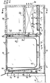
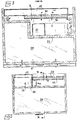
- the kitchen appliance shown in FIGS. 1 to 3 comprises a cooking table 10, an oven 12 supported above this table by uprights 14, and a cooking vapor extractor which comprises a vapor sensor 16 located under the oven 12 and a fan unit 18 disposed between the sensor 16 an orifice 20 for discharging the vapors.
- the fan unit 18 is arranged above the oven 12 and is connected to the vapor sensor 16 by a vertical chimney 22 disposed behind the rear wall 24 of the oven 12.
- the group 18 is installed behind the rear wall 26 of a storage cupboard 28 located above the oven, which is advantageous when the device is intended for equipment a kitchen of cramped dimensions where it is in the best interest to make the best use of the available space.
- the vapor sensor 16 comprises a flat collection chamber 30 extending over the entire underside of the oven 12 and communicating, on the one hand, with the outside by a metallic grease filter 32, of planar shape, constituting the bottom wall of the chamber 30, and, on the other hand, with the base 34 of the vertical chimney 22.
- a fire shutter 36 mounted to pivot about a horizontal axis 38 between a normal operating position (solid lines in FIG. 2) for which it is retained separated from the anti-grease filter 32 by a combustible support or fuse 40, and an alarm position (broken lines in FIG. 2) in which it falls by gravity after destruction of the support 40, and in which it cuts the communication between the grease filter 32 and the base 34 of the vertical chimney 22
- the shutter 36 is engaged with the operating key of a switch (shown diagrammatically at 42) controlling the electrical supply of the fan unit 18, so that the passage of this shutter 36 from its normal operating position to its position d alarm causes this switch to open and therefore group 18 to stop.
- the vapor extractor further comprises a duct 44 for suction of the vapors which are emitted at the upper part of the door 46 of the oven 12 when this door is in the "grill" position. , that is to say, ajar.
- This duct 44 extends horizontally above the furnace 12 between a suction mouth 48, adjacent to the upper edge of the door 46, and the vertical chimney 22.
- This duct 44 is equipped with a metallic anti-grease filter 50.
- the oven 12 is a double-wall oven, that is to say that it comprises an internal muffle 52 and an external envelope 54, between which a space is left 56.
- This space 56 is in communication, on the one hand, with the outside by air vents 58 (fig. 2) and 60 (fig. 1) located on the edges of the front face of the oven. 12 and, on the other hand, with the fan unit 18 by tubular passages 62 connected to holes made in the upper region of the outer casing 54 of the oven.
- An anti-odor filter 64 with activated carbon is placed in the air flow between the vertical chimney 22 and the discharge orifice 20. More specifically, in the apparatus of FIGS. 1 to 3, this filter 64 is placed in a vertical plane , between the chimney 22 and the fan unit 18.
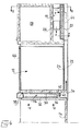
- FIGs 4 and 5 which illustrate a modified embodiment of the invention, elements similar to those of Figures 1 to 3 have been designated by the same reference numerals.
- the main modifications reside, on the one hand, in that the suction duct for the vapors emitted by the oven has been removed in its grill position, and, on the other hand, that group 18 does not provide plus the cooling of the walls of the oven 12, which oven may have its own cooling device (not shown).
- the discharge orifice 20 is located on the rear face of the device, and the anti-odor filter 64 is placed on this orifice and therefore downstream of the group 18.
Landscapes
- Engineering & Computer Science (AREA)
- Chemical & Material Sciences (AREA)
- Combustion & Propulsion (AREA)
- Mechanical Engineering (AREA)
- General Engineering & Computer Science (AREA)
- Electric Ovens (AREA)
- Electric Stoves And Ranges (AREA)
Claims (7)
Applications Claiming Priority (2)
| Application Number | Priority Date | Filing Date | Title |
|---|---|---|---|
| FR8124489 | 1981-12-30 | ||
| FR8124489A FR2519121B1 (fr) | 1981-12-30 | 1981-12-30 | Appareil de cuisine comprenant une table de cuisson, un four et un extracteur des vapeurs de cuisson |
Publications (2)
| Publication Number | Publication Date |
|---|---|
| EP0085178A1 EP0085178A1 (de) | 1983-08-10 |
| EP0085178B1 true EP0085178B1 (de) | 1985-02-13 |
Family
ID=9265519
Family Applications (1)
| Application Number | Title | Priority Date | Filing Date |
|---|---|---|---|
| EP19820111816 Expired EP0085178B1 (de) | 1981-12-30 | 1982-12-20 | Kücheneinrichtung mit einem Kochfeld, einem Backofen und einer Dunstabzugshaube |
Country Status (3)
| Country | Link |
|---|---|
| EP (1) | EP0085178B1 (de) |
| DE (1) | DE3262355D1 (de) |
| FR (1) | FR2519121B1 (de) |
Families Citing this family (2)
| Publication number | Priority date | Publication date | Assignee | Title |
|---|---|---|---|---|
| DE8716911U1 (de) * | 1987-12-23 | 1988-02-25 | Bosch-Siemens Hausgeräte GmbH, 8000 München | Backofen |
| CN106051853B (zh) | 2010-01-13 | 2019-08-27 | 奥义霍尔顿集团有限公司 | 烤箱排风罩方法、装置以及系统 |
Family Cites Families (5)
| Publication number | Priority date | Publication date | Assignee | Title |
|---|---|---|---|---|
| CH388224A (de) * | 1961-04-12 | 1965-02-28 | Locher Theodor | Einbaubackofen |
| US4143646A (en) * | 1977-10-27 | 1979-03-13 | Home Metal Products Company A Division Of Mobex Corporation | Cooking apparatus and exhaust system |
| DE2835397C3 (de) * | 1978-08-12 | 1981-10-15 | Neff - Werke, Carl Neff Gmbh, 7518 Bretten | Dunstabzugshaube zur Anordnung über Küchenherden |
| US4313043A (en) * | 1978-08-21 | 1982-01-26 | General Electric Company | Combination microwave oven and exhaust vent and installation mounting method therefor |
| GB2028491B (en) * | 1978-08-21 | 1982-09-08 | Gen Electric | Microwave oven and exhaust vent |
-
1981
- 1981-12-30 FR FR8124489A patent/FR2519121B1/fr not_active Expired
-
1982
- 1982-12-20 DE DE8282111816T patent/DE3262355D1/de not_active Expired
- 1982-12-20 EP EP19820111816 patent/EP0085178B1/de not_active Expired
Also Published As
| Publication number | Publication date |
|---|---|
| EP0085178A1 (de) | 1983-08-10 |
| DE3262355D1 (en) | 1985-03-28 |
| FR2519121B1 (fr) | 1986-09-12 |
| FR2519121A1 (fr) | 1983-07-01 |
Similar Documents
| Publication | Publication Date | Title |
|---|---|---|
| US12178358B2 (en) | Grilling appliance having air jacket for smoke removal and ventilation | |
| US5884619A (en) | Cook top intake director | |
| US4355434A (en) | Cannister type suction cleaner | |
| FR2472142A1 (fr) | Four comportant un element de chauffage de gril et au moins un autre element de chauffage ainsi qu'un ventilateur de circulation d'air | |
| US10716434B2 (en) | System for cleaning and enclosed bar-b-que | |
| US2226641A (en) | Ventilator | |
| US4858591A (en) | Kitchen smoke exhaust device | |
| KR200487625Y1 (ko) | 휴대용 흡기장치 | |
| CN104251505A (zh) | 家用抽吸机罩 | |
| EP0085178B1 (de) | Kücheneinrichtung mit einem Kochfeld, einem Backofen und einer Dunstabzugshaube | |
| CH631537A5 (fr) | Four domestique a gaz a deux enceintes de cuisson. | |
| US3021777A (en) | Grease extracting vent with heating means | |
| FR2672665A1 (fr) | Aspirateur pour foyers brulant des combustibles solides. | |
| KR100337195B1 (ko) | 육류 구이기 | |
| JPS6053817B2 (ja) | 調理用排気装置 | |
| EP1180648B1 (de) | Motorisierte Abzugshaube für Küchen | |
| CN214341671U (zh) | 一种炒菜机 | |
| FR2688993A1 (fr) | Dispositif de traitement des vapeurs pour friteuse. | |
| JP2891694B1 (ja) | 調理器 | |
| JP2677507B2 (ja) | グリル装置 | |
| CN223924889U (zh) | 一种排烟围炉 | |
| KR200377268Y1 (ko) | 황토 숯가마 고기 구이기 | |
| CN112438578A (zh) | 一种炒菜机 | |
| KR200206583Y1 (ko) | 숯 점화용 점화기 | |
| JPS6115965B2 (de) |
Legal Events
| Date | Code | Title | Description |
|---|---|---|---|
| PUAI | Public reference made under article 153(3) epc to a published international application that has entered the european phase |
Free format text: ORIGINAL CODE: 0009012 |
|
| AK | Designated contracting states |
Designated state(s): CH DE IT LI |
|
| 17P | Request for examination filed |
Effective date: 19830616 |
|
| ITF | It: translation for a ep patent filed | ||
| GRAA | (expected) grant |
Free format text: ORIGINAL CODE: 0009210 |
|
| AK | Designated contracting states |
Designated state(s): CH DE IT LI |
|
| REF | Corresponds to: |
Ref document number: 3262355 Country of ref document: DE Date of ref document: 19850328 |
|
| PLBE | No opposition filed within time limit |
Free format text: ORIGINAL CODE: 0009261 |
|
| STAA | Information on the status of an ep patent application or granted ep patent |
Free format text: STATUS: NO OPPOSITION FILED WITHIN TIME LIMIT |
|
| 26N | No opposition filed | ||
| ITTA | It: last paid annual fee | ||
| PGFP | Annual fee paid to national office [announced via postgrant information from national office to epo] |
Ref country code: DE Payment date: 19921201 Year of fee payment: 11 |
|
| PGFP | Annual fee paid to national office [announced via postgrant information from national office to epo] |
Ref country code: CH Payment date: 19931126 Year of fee payment: 12 |
|
| PG25 | Lapsed in a contracting state [announced via postgrant information from national office to epo] |
Ref country code: DE Effective date: 19940901 |
|
| PG25 | Lapsed in a contracting state [announced via postgrant information from national office to epo] |
Ref country code: LI Effective date: 19941231 Ref country code: CH Effective date: 19941231 |
|
| REG | Reference to a national code |
Ref country code: CH Ref legal event code: PL |