EP0085245A1 - Mengenregeleinrichtung für einen Kompressor in einer Kühlanlage - Google Patents
Mengenregeleinrichtung für einen Kompressor in einer Kühlanlage Download PDFInfo
- Publication number
- EP0085245A1 EP0085245A1 EP82306808A EP82306808A EP0085245A1 EP 0085245 A1 EP0085245 A1 EP 0085245A1 EP 82306808 A EP82306808 A EP 82306808A EP 82306808 A EP82306808 A EP 82306808A EP 0085245 A1 EP0085245 A1 EP 0085245A1
- Authority
- EP
- European Patent Office
- Prior art keywords
- compressor
- capacity
- rotation frequency
- change
- control device
- Prior art date
- Legal status (The legal status is an assumption and is not a legal conclusion. Google has not performed a legal analysis and makes no representation as to the accuracy of the status listed.)
- Granted
Links
- 238000006073 displacement reaction Methods 0.000 claims abstract description 29
- 239000003507 refrigerant Substances 0.000 claims description 12
- 238000005057 refrigeration Methods 0.000 claims description 3
- 238000004378 air conditioning Methods 0.000 abstract description 14
- 238000001816 cooling Methods 0.000 description 13
- 238000011156 evaluation Methods 0.000 description 13
- 238000010586 diagram Methods 0.000 description 9
- 239000007788 liquid Substances 0.000 description 6
- 238000010438 heat treatment Methods 0.000 description 3
- 239000000203 mixture Substances 0.000 description 2
- 238000010276 construction Methods 0.000 description 1
- 239000002184 metal Substances 0.000 description 1
- 238000012986 modification Methods 0.000 description 1
- 230000004048 modification Effects 0.000 description 1
- 230000000153 supplemental effect Effects 0.000 description 1
- 238000009423 ventilation Methods 0.000 description 1
Images


Classifications
-
- F—MECHANICAL ENGINEERING; LIGHTING; HEATING; WEAPONS; BLASTING
- F04—POSITIVE - DISPLACEMENT MACHINES FOR LIQUIDS; PUMPS FOR LIQUIDS OR ELASTIC FLUIDS
- F04C—ROTARY-PISTON, OR OSCILLATING-PISTON, POSITIVE-DISPLACEMENT MACHINES FOR LIQUIDS; ROTARY-PISTON, OR OSCILLATING-PISTON, POSITIVE-DISPLACEMENT PUMPS
- F04C28/00—Control of, monitoring of, or safety arrangements for, pumps or pumping installations specially adapted for elastic fluids
-
- G—PHYSICS
- G05—CONTROLLING; REGULATING
- G05D—SYSTEMS FOR CONTROLLING OR REGULATING NON-ELECTRIC VARIABLES
- G05D23/00—Control of temperature
- G05D23/19—Control of temperature characterised by the use of electric means
- G05D23/1919—Control of temperature characterised by the use of electric means characterised by the type of controller
-
- G—PHYSICS
- G05—CONTROLLING; REGULATING
- G05D—SYSTEMS FOR CONTROLLING OR REGULATING NON-ELECTRIC VARIABLES
- G05D23/00—Control of temperature
- G05D23/19—Control of temperature characterised by the use of electric means
- G05D23/20—Control of temperature characterised by the use of electric means with sensing elements having variation of electric or magnetic properties with change of temperature
- G05D23/24—Control of temperature characterised by the use of electric means with sensing elements having variation of electric or magnetic properties with change of temperature the sensing element having a resistance varying with temperature, e.g. a thermistor
Definitions
- This invention relates to a control system for controlling the operation of an air conditioning system, and more particularly, to a control circuit for a variable displacement compressor in an automobile air conditioning system.
- thermal control in the room gcncrally is accomplished by the intermittent operation of the air conditioning compressor through a magnetic clutch or motor.
- the magnetic clutch or motor is connected to the compressor and activated by a signal from a thermostat disposed in the room.
- the compressor In air conditioning systems for automobiles, the compressor usually is driven by the engine of the automobile. Since the r.p.m. of the automobile engine changes continuously; the rotation frequency of the compressor also changcs which in turn rapidly changes the cooling capacity of the air conditioner.
- Automobile air conditioners generally are designed so that when the compressor is driven by the engine at normal driving speed, the air conditioner operates at optimum capacity. Therefore, when the compressor is driven by the engine at lower operating speed, or during idling, the cooling capacity of the air conditioner is insufficient in comparison with the refrigerating or cooling load. Also, when the compressor is driven by the engine at high operating speed, the cooling capacity is higher than necessary.
- One known mechanism for controlling the excessive cooling capacity of an air conditioner operates by heating part of the cool air generated by the air conditioner. Part of the cool air from the evaporator of the air conditioner passes a heating unit which heats the cool air and this heated air is mixed with the remaining cool air to control the temperature of the air which is blown into the room or compartment. In this mechanism, the ratio of cooling capacity to heating capacity is controlled in response to driving frequency. This mechanism for controlling air temperature is complicated and considerable energy is spent to reheat the cool air by using engine power.
- the magnetic clutch which is disposed on the compressor and connected between the engine and the compressor to transmit rotating motion is intermittently operated to control the operation of the compressor.
- the magnetic clutch since the magnetic clutch may be operated at high rotation frequency, a sudden force is generated at the moment the clutch is engaged and this sudden force is transmitted to the engine and the compressor. Also, the temperature of the air blown Into the compartment drastically changes upon operation of the compressor.
- the present invention is directed to a capacity control device for a compressor in a refrigerating or air conditioning system.
- the compressor includes a variable displacement device for changing the capacity of the compressor.
- the capacity control device controls the operation of the variable displacement device to change the capacity of the compressor from a large capacity to a small capacity, in response to the required refrigerating capacity and the actual rotation frequency of the compressor.
- the capacity control device includes a frequency evaluation circuit for evaluating the required rotation frequency of the compressor, when the compressor is operating at small volume or capacity, in order to satisfy the required refrigerating capacity.
- the required refrigerating capacity is determined by the frequency evaluation circuit as a function of the temperature of the incoming air.
- a voltage representing the required rotation frequency of the compressor operating at small volume i.e., the required small volume rotation frequency
- a voltage comparator With a voltage representing the actual rotation frequency of the compressor. This latter voltage is generated by a frequency to voltage converter which converts an incoming pulse signal representing the rotation of the compressor to a DC voltage signal. If the required small volume rotation frequency is smaller than the actual rotation frequency, the voltage comparator generates a signal which causes the compressor to operate at small volume and vice versa if the small volume rotation frequency is larger than the actual rotation frequency.
- FIG. I the basic construction of an air conditioning or refrigerating system, particularly, an automobile air conditioner, is shown.
- This air conditioning system comprises compressor I, condenser 2, receiver and dryer 3 , a thermostatic expansion device or valve 4 and evaporator 5. These five basic components are caupled in series to form a conventional closed vapor cycle refrigeration circuit.
- Refrigerant gas is compressed in compressor I and supplied to condenser 2 where it is condensed to liquid refrigerant and cooled by forced ventilation of fan 6.
- the liquid refrigerant is accumulated in receiver and dryer 3 , which removes the moisture and metal chips in the liquid refrigerant.
- the liquid refrigerant within receiver and dryer 3 is delivered to thermostatic expansion valve 4 .
- the refrigerant expands as it flows through valvc 4 and emerges as a two-phase mixture of liquid and gas, but primarily liquid.
- evaporator 5 acts as a hcat exchanger in conjunction with blower 7 which supplies air to the vehicle compartment, heat is transferred from the incoming air to the refrigerant and the entirety of the refrigerant vaporizes and assumes its gaseous state.
- the refrigerant gas at the evaporator outlet then is passed to the suction inlet of compressor i.
- Compressor i which is shown in block diagram form in Figure I, is a variable displacement compressor.
- compressor i is a scroll type compressor including a variable displacement device as shown in copending European patent application No. 82301205.9 filed on March 9, 1982 and copending European patent application No. 82300 102.0 filed on December 15, 1982.
- Compressor I is controlled by operation of magnetic clutch 8 and variable displacement device 9 which changes the refrigerating capacity thereof.
- Magnetic clutch 8 is controlled by operation of a conventional thermostat 8' and variable displacement device 9 is controlled by operation of capacity control circuit io, which is described in further detail below in connection with Figure 3 .
- Capacity control circuit 10 is connected to voltage source E by on/off switch S.
- compressor I includes a variable displacement device which is capable of changing the refrigerating or cooling capacity of the compressor.
- the capacity of the compressor shown in Figure I can be changed to one of two conditions, C 1 or C 2 , as shown in Figure 2 .
- curve C is the normal capacity of prior art compressors.
- the variable displacement device of compressor I includes at least one valve as shown in patent applications Nos. 82301205.9 and 82. 306 702.0 and this valve is controlled by solenoid 9 shown in Figure I. Solenoid 9 is connected to voltage source E through capacity control circuit 10 and main air conditioning on/off switch S.
- Capacity control circuit 10 for controlling the variable displacement device of compressor i is shown.
- the capacity control circuit includes relay Ry I to control operation of solenoid valve SV which actuates the variable displacement device to change the capacity of compressor I.
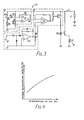
- Capacity control circuit 10 further includes small volume frequency evaluation circuit A which detects air temperature and computes the required rotation frequency as a function of temperature of compressor I operating at small volume C 2 (i.e., the required small volume rotation frequency), frequency to voltage converter circuit B to detect the actual rotation frequency of the compressor and comparison circuit C to compare the voltage outputs from small volume frequency evaluation circuit A and converter circuit B to control operation of relay Ry l .
- Small volume frequency evaluation circuit A includes temperature sensing thermistor Th and comparator II.
- Thermistor Th is mounted on the air inlet of evaporator 5 in order to detect the temperature of incoming air.
- a voltage divider formed by thermistor Th and resistor R I supplies voltagc Va to inverting input terminal (-) of comparator II via resistor R 4 .
- Voltage Va which is inversely related to the temperature of the incoming air, is reference voltage Vb, which is generated by a voltage divider formed by resistors R 2 and R 3 .
- Voltage Vb is applied to a noninverting input terminal (+) of comparator II.
- a feedback resistor K S is connected across comparator ii from the output terminal of comparator II to the inverting input terminal (-).
- the required refrigerating capacity is directly related to the incoming air temperature.
- the refrigerating capacity Q is directly related to the rotation frequency of the compressor. Accordmgly, as apparent from Figure 2, the rotation frequency Nc 2 at which compressor I can continue to operate at small volume C 2 can be easily calculated as a function of the required refrigerating capacity Q. Since refrigerating capacity also varies as a function of temperature as discussed above in connection with Figure 4, the required rotation frequency of the compressor can be easily determined as a function of incoming air temperature.
- Frequency cvaluation circuit A takes into account the above relationships between the refrigerating capacity Q and both the incoming air temperature (t) and the rotation frequency Nc 2 of the compressor operating at small volume C 2 .
- Frequency evaluation circuit A generates an output voltage which corresponds to the required rotation frequency Nc 2 for the compressor to continue operating at small volume C 2 as a function of refrigerating capacity.
- the refrigerating capacity is determined in frequency evaluation circuit A as a function of incoming air temperature based on the relationship shown in Figure 4 and the rotation frequency Nc 2 is determined as a function of refrigerating capacity based on the relationship shown in Figure 2.
- the values of resistors R 4 and R 5 , as well as the values of the other elements in frequency evaluation circuit A, are set in accordance with the relationships shown in Figures 2 and 4 .
- Frequency to voltage converter circuit B receives a pulse signal from a conventional rotation sensor (not shown) mounted on the cngine or compressor. For example, such a sensor could be mounted adjacent the rotating shaft of the compressor or engine to sense the rotation frequency of the shaft.
- Converter circuit B is a conventional frequency to voltage converter which includes a rectifier circuit basically formed by diodes D 1 and D 2 and a voltage comparator circuit basically formed by voltage comparator 14 .
- the output of voltage comparator 14 which is also the output Vd of converter circuit B, is a voltage signal which varies in accordance with variations in the rotation frequency of compressor i.
- the voltage output Vo of small volume frequency evaluation circuit A is compared at comparator 1 2 of comparison circuit C with the output voltage Vd of frequency to voltage converter circuit B.
- the output of comparator 12 is coupled to the base circuit of switching transistor Tr.
- Relay Ry 1 is connected to the collector of transistor Tr and its operating contact is connected in series with solenoid valve SV. When transistor Tr is conductive, relay Ry 1 is energized so that solenoid valve SV actuates the variable displacement device to change the displacement of compressor I from large volume C 1 to small volume C 2 .
- capacity control circuit 10 When main switch S is actuated to connect the voltage source at start step 101, the capacity control circuit is ready for operation.
- the air temperature is detected and used by small volume frequency evaluator circuit A to compute the required refrigerating capacity Q of compressor 1.
- the required rotation frequency Nc 2 After computing the required capacity at step 103, the required rotation frequency Nc 2 to obtain the required refrigerating capacity from step 102 is determined.
- the actual rotation frequency NE of compressor I is compared to the calculated or required rotation frequency Nc 2 from step 103 . If the actual rotation frequency NE of the compressor is higher than the calculated rotation frequency Nc 2 , the required refrigerating capacity Q is already obtained.
- FIG. 6 another embodiment of the present invention is shown.
- the evaluation circuit A is replaced by a voltage divider A' which defines the predetermined rotation frequency Nc 2 of the compressor.
- the voltage divider A' comprises resistors R 6 and R 7 which provide a reference voltage Vc to the non-inverted input terminal (+) of comparator 12.
- the reference voltage Vc' generated by voltage divider A 1 which corresponds to the predetermined rotation frequency Nc 2 , is compared at comparator 12 with output voltage Vd of converter circuit B.
- the actual rotation frequency of the compressor is compared to the predetermined rotation frequency Nc 2 by comparator circuit C to determine whether the compressor should be operated at small volume C 2 or large volume C 2 If the actual rotation frequency is smaller than the predetermined rotation frequency Nc 2 , i.e., voltage Vd is smaller than voltage Vc, then the output of comparator C is low which turns on transistor Tr and energizes relay Ry 1 . Relay Ry 1 in turn actuates solenoid SV which causes the cc.mpressor to operate at small volume C 2 . If the actual rotation frequency is larger than the predetermined rotation frequency Nc 2 , then the compressor operates at large volume C 1-
Landscapes
- Engineering & Computer Science (AREA)
- Physics & Mathematics (AREA)
- General Physics & Mathematics (AREA)
- Automation & Control Theory (AREA)
- Mechanical Engineering (AREA)
- General Engineering & Computer Science (AREA)
- Control Of Positive-Displacement Pumps (AREA)
- Control Of Positive-Displacement Air Blowers (AREA)
Applications Claiming Priority (2)
| Application Number | Priority Date | Filing Date | Title |
|---|---|---|---|
| JP206626/81 | 1981-12-21 | ||
| JP56206626A JPS58105821A (ja) | 1981-12-21 | 1981-12-21 | 車輌用空調装置の制御装置 |
Publications (2)
| Publication Number | Publication Date |
|---|---|
| EP0085245A1 true EP0085245A1 (de) | 1983-08-10 |
| EP0085245B1 EP0085245B1 (de) | 1986-07-23 |
Family
ID=16526480
Family Applications (1)
| Application Number | Title | Priority Date | Filing Date |
|---|---|---|---|
| EP82306808A Expired EP0085245B1 (de) | 1981-12-21 | 1982-12-20 | Mengenregeleinrichtung für einen Kompressor in einer Kühlanlage |
Country Status (4)
| Country | Link |
|---|---|
| EP (1) | EP0085245B1 (de) |
| JP (1) | JPS58105821A (de) |
| AU (1) | AU559316B2 (de) |
| DE (1) | DE3272218D1 (de) |
Cited By (3)
| Publication number | Priority date | Publication date | Assignee | Title |
|---|---|---|---|---|
| US5303559A (en) * | 1992-12-31 | 1994-04-19 | Micropump Corporation | Method and apparatus for refrigerant recovery |
| FR2766909A1 (fr) * | 1997-08-01 | 1999-02-05 | Valeo Climatisation | Procede et dispositif pour detecter une pression excessive d'un fluide refrigerant dans un condenseur d'une boucle de climatisation |
| EP1262723A1 (de) * | 2001-06-01 | 2002-12-04 | BSH Bosch und Siemens Hausgeräte GmbH | Kältegerät |
Families Citing this family (1)
| Publication number | Priority date | Publication date | Assignee | Title |
|---|---|---|---|---|
| JP2003002048A (ja) | 2000-08-28 | 2003-01-08 | Denso Corp | 車両用空調装置 |
Citations (3)
| Publication number | Priority date | Publication date | Assignee | Title |
|---|---|---|---|---|
| CH173493A (de) * | 1933-09-29 | 1934-11-30 | Sulzer Ag | Verdichter mit sichelförmigem Arbeitsraum, insbesondere bei Kältemaschinen. |
| DE1403516A1 (de) * | 1960-02-26 | 1968-10-31 | Linde Ag | Verfahren zur Regelung der Foerdermenge von Drehkolbenverdichtern der Vielzellenbauart und Vorrichtung zur Durchfuehrung des Verfahrens |
| US3924972A (en) * | 1974-10-29 | 1975-12-09 | Vilter Manufacturing Corp | Control means for a variable capacity rotary screw compressor |
Family Cites Families (2)
| Publication number | Priority date | Publication date | Assignee | Title |
|---|---|---|---|---|
| DE2502184A1 (de) | 1975-01-21 | 1976-07-22 | Bosch Gmbh Robert | Verfahren und vorrichtung zum steuern einer kaelteanlage in einem kraftfahrzeug |
| JPS5564174A (en) * | 1978-11-02 | 1980-05-14 | Toyo Kiyaria Kogyo Kk | Car air conditioner |
-
1981
- 1981-12-21 JP JP56206626A patent/JPS58105821A/ja active Pending
-
1982
- 1982-12-20 DE DE8282306808T patent/DE3272218D1/de not_active Expired
- 1982-12-20 EP EP82306808A patent/EP0085245B1/de not_active Expired
- 1982-12-21 AU AU91728/82A patent/AU559316B2/en not_active Ceased
Patent Citations (3)
| Publication number | Priority date | Publication date | Assignee | Title |
|---|---|---|---|---|
| CH173493A (de) * | 1933-09-29 | 1934-11-30 | Sulzer Ag | Verdichter mit sichelförmigem Arbeitsraum, insbesondere bei Kältemaschinen. |
| DE1403516A1 (de) * | 1960-02-26 | 1968-10-31 | Linde Ag | Verfahren zur Regelung der Foerdermenge von Drehkolbenverdichtern der Vielzellenbauart und Vorrichtung zur Durchfuehrung des Verfahrens |
| US3924972A (en) * | 1974-10-29 | 1975-12-09 | Vilter Manufacturing Corp | Control means for a variable capacity rotary screw compressor |
Cited By (4)
| Publication number | Priority date | Publication date | Assignee | Title |
|---|---|---|---|---|
| US5303559A (en) * | 1992-12-31 | 1994-04-19 | Micropump Corporation | Method and apparatus for refrigerant recovery |
| EP0604700A1 (de) * | 1992-12-31 | 1994-07-06 | Micropump, Inc. | Verfahren und Vorrichtung zur Rückgewinnung von Kältemittel |
| FR2766909A1 (fr) * | 1997-08-01 | 1999-02-05 | Valeo Climatisation | Procede et dispositif pour detecter une pression excessive d'un fluide refrigerant dans un condenseur d'une boucle de climatisation |
| EP1262723A1 (de) * | 2001-06-01 | 2002-12-04 | BSH Bosch und Siemens Hausgeräte GmbH | Kältegerät |
Also Published As
| Publication number | Publication date |
|---|---|
| JPS58105821A (ja) | 1983-06-23 |
| AU9172882A (en) | 1983-06-30 |
| DE3272218D1 (en) | 1986-08-28 |
| EP0085245B1 (de) | 1986-07-23 |
| AU559316B2 (en) | 1987-03-05 |
Similar Documents
| Publication | Publication Date | Title |
|---|---|---|
| US4485635A (en) | Control device for a compressor in a refrigerating system | |
| US5568732A (en) | Air conditioning apparatus and method of controlling same | |
| US6523361B2 (en) | Air conditioning systems | |
| US4539821A (en) | Capacity control device for controlling a variable displacement compressor in an air conditioning system | |
| EP0085246A1 (de) | Regelkreis für einen Kompressor mit veränderter Verdrängung einer Klimaanlage | |
| US5701753A (en) | Air conditioning apparatus | |
| US5533352A (en) | Forced air heat exchanging system with variable fan speed control | |
| CA1257366A (en) | Device for controlling capacity of compressor | |
| CA1252177A (en) | Device for controlling the capacity of a variable capacity compressor | |
| US5588589A (en) | Air conditioner | |
| US4794762A (en) | Refrigerant flow control system | |
| GB2152246A (en) | Control apparatus for an air conditioner | |
| US4934157A (en) | Apparatus for controlling a variable displacement refrigerant compressor for a car air-conditioner | |
| EP1004828A2 (de) | Verfahren zur Steuerung des Kühlverhaltens einer Klimaanlage | |
| US4498311A (en) | Control device for a variable displacement compressor in an air conditioning system | |
| US20080295530A1 (en) | Compressor inlet pressure estimation apparatus for refrigeration cycle system | |
| EP0085245B1 (de) | Mengenregeleinrichtung für einen Kompressor in einer Kühlanlage | |
| JP3253104B2 (ja) | 冷凍サイクル装置 | |
| JPH06317357A (ja) | 空気調和機 | |
| EP0118573B1 (de) | Leistungsfähigkeitssteuervorrichtung für einen mengenregelbaren Verdichter in einer Klimaanlage | |
| EP0119341B2 (de) | Steuervorrichtung für einen mengenregelbaren Verdichter in einer Klimaanlage | |
| JP3105285B2 (ja) | 空気調和機 | |
| JP2845981B2 (ja) | 車両用空調装置 | |
| JP3961107B2 (ja) | 外部制御式可変容量コンプレッサのトルク予測装置およびこれを用いた自動車エンジン制御装置 | |
| JPH05240493A (ja) | 空気調和機 |
Legal Events
| Date | Code | Title | Description |
|---|---|---|---|
| PUAI | Public reference made under article 153(3) epc to a published international application that has entered the european phase |
Free format text: ORIGINAL CODE: 0009012 |
|
| AK | Designated contracting states |
Designated state(s): DE FR GB IT SE |
|
| 17P | Request for examination filed |
Effective date: 19840208 |
|
| R17P | Request for examination filed (corrected) |
Effective date: 19840208 |
|
| ITF | It: translation for a ep patent filed | ||
| GRAA | (expected) grant |
Free format text: ORIGINAL CODE: 0009210 |
|
| AK | Designated contracting states |
Kind code of ref document: B1 Designated state(s): DE FR GB IT SE |
|
| REF | Corresponds to: |
Ref document number: 3272218 Country of ref document: DE Date of ref document: 19860828 |
|
| ET | Fr: translation filed | ||
| PLBI | Opposition filed |
Free format text: ORIGINAL CODE: 0009260 |
|
| 26 | Opposition filed |
Opponent name: ROBERT BOSCH GMBH Effective date: 19870422 |
|
| RDAG | Patent revoked |
Free format text: ORIGINAL CODE: 0009271 |
|
| STAA | Information on the status of an ep patent application or granted ep patent |
Free format text: STATUS: PATENT REVOKED |
|
| GBPR | Gb: patent revoked under art. 102 of the ep convention designating the uk as contracting state | ||
| 27W | Patent revoked |
Effective date: 19881107 |
|
| GBPC | Gb: european patent ceased through non-payment of renewal fee | ||
| PGFP | Annual fee paid to national office [announced via postgrant information from national office to epo] |
Ref country code: LU Payment date: 19891003 Year of fee payment: 8 |
|
| EUG | Se: european patent has lapsed |
Ref document number: 82306808.5 |