EP0085248A1 - Verdrängermaschine von Umlaufkolbentyp mit innerem Ausgleichsgewicht - Google Patents
Verdrängermaschine von Umlaufkolbentyp mit innerem Ausgleichsgewicht Download PDFInfo
- Publication number
- EP0085248A1 EP0085248A1 EP82306811A EP82306811A EP0085248A1 EP 0085248 A1 EP0085248 A1 EP 0085248A1 EP 82306811 A EP82306811 A EP 82306811A EP 82306811 A EP82306811 A EP 82306811A EP 0085248 A1 EP0085248 A1 EP 0085248A1
- Authority
- EP
- European Patent Office
- Prior art keywords
- orbiting
- piston type
- casing
- type fluid
- cylindrical member
- Prior art date
- Legal status (The legal status is an assumption and is not a legal conclusion. Google has not performed a legal analysis and makes no representation as to the accuracy of the status listed.)
- Withdrawn
Links
- 239000012530 fluid Substances 0.000 title claims abstract description 66
- 238000006073 displacement reaction Methods 0.000 title description 13
- 239000011796 hollow space material Substances 0.000 claims abstract description 6
- 238000007373 indentation Methods 0.000 claims description 12
- 238000005192 partition Methods 0.000 claims description 3
- 230000002093 peripheral effect Effects 0.000 description 7
- 230000008859 change Effects 0.000 description 3
- 230000007246 mechanism Effects 0.000 description 3
- 230000008901 benefit Effects 0.000 description 2
- 238000010276 construction Methods 0.000 description 2
- 230000004048 modification Effects 0.000 description 2
- 238000012986 modification Methods 0.000 description 2
- 238000004891 communication Methods 0.000 description 1
- 238000007796 conventional method Methods 0.000 description 1
- 230000008878 coupling Effects 0.000 description 1
- 238000010168 coupling process Methods 0.000 description 1
- 238000005859 coupling reaction Methods 0.000 description 1
- 238000007599 discharging Methods 0.000 description 1
- 239000004519 grease Substances 0.000 description 1
- 238000003780 insertion Methods 0.000 description 1
- 230000037431 insertion Effects 0.000 description 1
- 238000004519 manufacturing process Methods 0.000 description 1
- 230000035515 penetration Effects 0.000 description 1
- 230000009467 reduction Effects 0.000 description 1
- 238000010008 shearing Methods 0.000 description 1
- 125000006850 spacer group Chemical group 0.000 description 1
- 238000012546 transfer Methods 0.000 description 1
Images








Classifications
-
- F—MECHANICAL ENGINEERING; LIGHTING; HEATING; WEAPONS; BLASTING
- F01—MACHINES OR ENGINES IN GENERAL; ENGINE PLANTS IN GENERAL; STEAM ENGINES
- F01C—ROTARY-PISTON OR OSCILLATING-PISTON MACHINES OR ENGINES
- F01C1/00—Rotary-piston machines or engines
- F01C1/02—Rotary-piston machines or engines of arcuate-engagement type, i.e. with circular translatory movement of co-operating members, each member having the same number of teeth or tooth-equivalents
- F01C1/04—Rotary-piston machines or engines of arcuate-engagement type, i.e. with circular translatory movement of co-operating members, each member having the same number of teeth or tooth-equivalents of internal-axis type
- F01C1/045—Rotary-piston machines or engines of arcuate-engagement type, i.e. with circular translatory movement of co-operating members, each member having the same number of teeth or tooth-equivalents of internal-axis type having a C-shaped piston
-
- F—MECHANICAL ENGINEERING; LIGHTING; HEATING; WEAPONS; BLASTING
- F01—MACHINES OR ENGINES IN GENERAL; ENGINE PLANTS IN GENERAL; STEAM ENGINES
- F01C—ROTARY-PISTON OR OSCILLATING-PISTON MACHINES OR ENGINES
- F01C17/00—Arrangements for drive of co-operating members, e.g. for rotary piston and casing
- F01C17/06—Arrangements for drive of co-operating members, e.g. for rotary piston and casing using cranks, universal joints or similar elements
- F01C17/063—Arrangements for drive of co-operating members, e.g. for rotary piston and casing using cranks, universal joints or similar elements with only rolling movement
-
- F—MECHANICAL ENGINEERING; LIGHTING; HEATING; WEAPONS; BLASTING
- F05—INDEXING SCHEMES RELATING TO ENGINES OR PUMPS IN VARIOUS SUBCLASSES OF CLASSES F01-F04
- F05B—INDEXING SCHEME RELATING TO WIND, SPRING, WEIGHT, INERTIA OR LIKE MOTORS, TO MACHINES OR ENGINES FOR LIQUIDS COVERED BY SUBCLASSES F03B, F03D AND F03G
- F05B2250/00—Geometry
- F05B2250/20—Geometry three-dimensional
- F05B2250/23—Geometry three-dimensional prismatic
- F05B2250/231—Geometry three-dimensional prismatic cylindrical
Definitions
- This invention relates to a fluid displacement apparatus, and more particularly, to a fluid displacement apparatus of the orbiting piston type for use as a supercharger for an engine or as an air compressor.
- fluid apparatus capable for use as air pumps or compressors.
- One well known machine is a velocity type compressor or blower which can handle a large air flow due to the high rotational speed of a fan blade.
- Another type of fluid apparatus is the fluid displacement apparatus, for example a piston- type fluid apparatus or a rotary vane type fluid apparatus, which can handle large pressure of fluid due to the enclosure of the fluid within a cylinder, and its discharge against the pressure at a discharge side.
- the supercharger for an engine which is designed to increase the output of the engine by supercharging the suction air, must have intermediate character between the velocity type apparatus and fluid displacement apparatus, i.e. compress air at about 0 . 5 pressure above atmospheric pressure, and handle an air flow at 5 -iom 3 /min. Furthermore, the supercharger must be compact and lightweight, because the supercharger is preferably located within the engine compartment, which is already designed, without any influence on the other mechanisms connected with the engine. In prior superchargers, which have been driven by the engine through a rotation transmitting device, for example, a gear or belt, the output of the engine, which is improved by the supercharging of supercharger, has generally not been sufficiently large to drive the supercharger.
- the supercharger is usually driven over a large range of rotational speeds, so that both high volume efficiency and total pressure efficiency have not been attained. Furthermore, the supercharger requires a change over device to control the supercharging and non-supercharging operations, as occasion demands however, prior mechanisms which have controlled the change over device have not attained smooth change over operation.
- An orbiting piston type fluid apparatus includes a housing having a cylindrical casing and a front end platc, attached to one end opening of the casing.
- a cylindrical core member is located in the center portion of the casing and has an outer surface concentric with the inner surface of the casing.
- a blade axially extends within the space between the casing and core member.
- An orbiting cylindrical member is disposed in an annular space defined between the inner surface of the casing and the outer surface of the core member to form a working fluid chamber, and has a slot for passage of the blade in a radial direction.
- a drive shaft is rotatably supported by the housing at both end portion thereof.
- the orbiting cylindrical member is supported .for orbital motion by eccentric crank portions disposed on both end portions of the drive shaft, which carry the orbiting cylindrical member through bearings.
- the core member has a hollow space at its center portion. A balanceweight which cancels the unbalance caused by the orbital motion is assembled on the drive shaft within the hollow space of the core member.
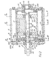
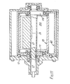
- Apparatus i includes a housing 10 having a cylindrical or cup shaped casing 11 with one end opening closed by an end plate member 111.
- a front end plate 12 is attached to other end opening of cylindrical casing 11 by a plurality of bolts 13 .
- the end openings of cylindrical casing 11 are thus covered by end plate member 111 and front end plate 12 to seal off the inner chamber of casing 11.
- a rectangular shaped projection 112 projects from the outer peripheral surface of cylindrical casing 11 and extends from the front end portion of the casing 11 to its rear end portion to form a rectangular opening.
- a blade or partition 14 is located within the rectangular opening and extends axially to define a suction port 15 and discharge port 1 6 within the opening. Each longitudinal end of partition 14 is attached to projection 112.
- An opening 121 is formed in the center of front end plate 12 for passage or penetration of a drive shaft 17 .
- An annular sleeve 122 projects from the front end surface of front end plate 12 and surrounds drive shaft 17 .
- the outer end of drive shaft 17 which extends from sleeve 122 is connected to a rotation transmitting device which may be disposed on the outer peripheral surface of sleeve 122 for transmitting rotational movement to drive shaft 17 .
- Drive shaft 17 is rotatably supported by front end plate 12 and end plate member 111 of cylindrical casing 11 through two bearings 1 8 and 19.
- Bearing 1 8 is located within opening 121 of front end plate 12 and the other bearing 19 is located within an annular depression 113 of end plate member 111.
- a cylindrical core member 20 is arranged on and around drive shaft 17 , and supported by drive shaft 17 through bearings 21 and 22 .
- the outer peripheral surface of cylindrical core member 20 is concentric with the inner surface of cylindrical casing 11.
- Cylindrical core member 20 has a cylindrical cavity 201 at its center portion and two supporting members 202 and 203 at both end portions of cylindrical cavity 201 .
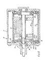
- Supporting members 202 and 203 extend radially inward from the inner surface of core member 20 and are supported on drive shaft 17 through bearings 21 and 22 . Furthermore, the inner end portion of blade 14 is fixed on the outer peripheral surface of cylindrical core member 20 , as shown in Figure 3 , to fixedly locate it within the inner chamber of cylindrical casing 11. As shown in Figure 2 , one supporting member, support member 202 , is formed separately from the cylindrical core member 20 and is fitted in the inner surface of cylindrical core member 20 . Alternatively, cylindrical core member 20 may be fixed by blade 14 alone, as shown in Figure 11, or supported by one supporting member 204 formed in the center portion of its inner wall, as shown in Figure 10.
- Drive shaft 17 has two eccentric crank portions 171 and 172 attached at both end portions of drive shaft 17 and located in the same angular postion.
- Eccentric crank portion 171 which is located closest to front end plate 12 , is formed separately from drive shaft 17 and fixed on drive shaft 17 by a key 211.
- An orbiting cylindrical member 23 is disposed within the inner chamber of cylindrical casing 11 and surrounds cylindrical core member 20. One end opening of orbiting cylindrical member 23 is closed by block end plate 231 , and the other by block end plate 232 .
- the orbiting cylindrical member 23 is supported by drive shaft 17 through crank portions 171 and 172 and two bearings 24 and 25 which are located between the outer peripheral surfaces of crank portions 171 and 172 and the inner peripheral surfaces of end plates 231 and 232 .
- Orbiting cylindrical member 23 has an axially extending slot 233 to prevent interference between orbiting cylindrical member 23 and blade 14 during the orbital motion of orbiting cylindrical member 23 .
- the front block end plate 231 is formed separately from orbiting cylindrical member 23 to permit the insertion of core member 20 .
- Front block end plate 231 is fixed on the end portion of orbiting cylindrical member 23 by any suitable conventional technique.
- a rotation preventing device 2 6 is located between the inner end surface of front end plate 12 and the axial end surface of block end plate 231 of orbiting cylindrical member 23 .
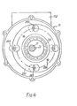
- Rotation preventing device 2 6 includes an orbiting ring 2 6 1 which is fastened against the end surface of block end plate 231 , a fixed ring 2 6 2 which is fastened against the inner end surface of front end plate 12 , and bearing elements, such as a plurality of spherical balls 2 6 5 .
- Both rings 2 6 1 and 2 6 2 have a plurality of pairs of adjacent circular indentations or holes 2 6 3 and 2 6 4 .
- both rings 2 6 1 and 2 6 2 are formed of separate plate elements 2 6 1 a and 2 6 2 a, each of which are respectively fixed on an end surface by pins 2 66 (Fig. 4 ), and ring elements 2 6ib and 2 6 2 b which have the plurality of pairs of holes 2 6 3 and 2 6 4 .
- the plate and ring elements may be formed integral with one another.
- rotation preventing device 2 6 is located between the inner surface of front end plate 12 and one end surface of orbiting cylindrical member 23 .
- another rotation preventing device 2 6' may be located between an inner surface of end plate member 111 of casing 11and other end surface of orbiting cylindrical member 23 to prevent twisting of orbiting cylindrical member. If rotating motion of orbiting cylindrical member 23 is prevented by only one rotation preventing device located between the first end plate and one end surface of orbiting cylindrical member 23 , the other end portion of orbiting cylindrical member 23 is free to rotate, so that twisting motion may be caused.
- a balanceweight 27 is fixed on drive shaft 17 by a key 2 8 and is disposed within a cylindrical cavity of core member 20 to hold the dynamic balance of the apparatus.
- the centroid of balanceweight 27 is angularly offset 180° from the angular location of eccentric crank portions 171 and 172 .
- cut-out portions 2 6 7 are formed in orbiting ring 2 6 1 as shown in Figure 7 , to coincide the centroid of the orbiting cylindrical member 23 with the axis of drive shaft 17 since the orbiting cylindrical member 23 is formed with slot 233 , which would cause an unbalance.
- the parts which define the working chamber of the apparatus move through a noncontacting point with respect to one another, i.e., a gap between the outer surface of core member 20 and the inner wall surface of orbiting cylindrical member 23 , and a gap between the inner surface of cylindrical casing 11 and the outer wall surface of orbiting cylindrical member 23 are created with minimum clearance to prevent interference of the parts caused by the eccentricity of the parts which results in manufacturing.
- Figure 9 a the longitudinal axis of the eccentric crank portion is shown at its top vertical position or at 0°.
- the point of tangency Q 4 between the inner wall surface of orbiting cylindrical member 23 and the outer peripheral surface of core member 20 defines an inner fluid chamber B which has two sections, each extending from the point of tangency to opposite side of blade 14 .
- an outer fluid chamber A which extends substantially from one side of blade 14 to the other, is also formed between the outer wall surface of orbiting cylindrical member 23 and the inner wall of cylindrical casing 11.
- Figure gb shows the state of the orbiting cylindrical member 23 at a drive shaft crank angle which is advanced a° from that in Figure 9 a.
- the volume of inner fluid chamber B is increased to take in fluid, as shown in Figure ga- 9 d.
- the inner fluid chamber B is sealed off, as shown in Figure 9 f, and simultaneously connected with the discharge port 15 through a clearance between the left end portion of orbiting cylindrical member 23 and core member 20 .
- the volume of the inner fluid chamber B is gradually reduced due to further orbital motion of member 23 , as shown in Figures 9 a- 9 c.
- the discharging of fluid within the inner fluid chamber B thus continues until the inner wall surface of left end portion of orbiting cylindrical member 23 contacts the outer wall surface of core member 20 .
- a new inner fluid chamber B' is formed to take in fluid.
- suction port 15 is in fluid communication with discharge port 1 6 while passing the stages from Figure gh to Figure 9 b, and also while passing the stages from Figure 9d to Figure 9f.
- the apparatus can operate at a pressure ratio i or 2 without causing problems.
- the apparatus can be made with an orbiting cylindrical member having a comparatively small radius, so that the apparatus can be operated at high speeds without expending great energy to thereby shorten the time during which the suction and discharge ports are connected.
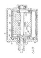
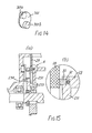
- FIG. 12 - 15 another embodiment is shown.
- This embodiment is directed to a modification of the orbiting cyiin- drical member to improve the volumetric efficiency by filling in the gap between the axial end surface of the blade and the opposite surface as far as possible.
- an annular axial projection 233 extends from the center portion of axial end surface of front block end plate 231
- a radial flange portion 234 extends radially outward from the outer end portion of annular projection 233 .
- Radial flange portion 234 thus is located at an axially spaced distance from the front end surface of front block end plate 231 .
- the outer diameter of radial flange portion 234 is formed the same as outer diameter of orbiting cylindrical member 23 .
- An annular plate 29 is fixed on one end surface of casing 11, and extends radially inward into the space between flange portion 234 and block end plate 23t
- a rotation preventing device 30 for example, a crank type coupling mechanism is located between the inner surface of front end plate 12 and an end surface of radial flange portion 234 .
- rotation preventing device 30 includes a plurality of cranks 301, as shown in Figure 14 , and pairs of adjacent circular indentations 302 and 303 formed on the front end plate 12 and radial flange portion 234 .
- Crank shaft portions 30 ia and 30I b of crank 301 are inserted into indentations 302 and 303 to permit smooth orbital movement without rotation.
- Bearings 305 are preferably interposed between crank shaft portions 30 ia, 30I b and indentations 302 and 303.
- the gap between the axial end surface of the blade and the fixed element 20 which defines the working chamber is formed smaller, thus improving the volumetric efficiency.
- annular groove 32 is formed on the axial end surface of block end plate 231 and a seal element 33 is placed within groove 32 .
- the area containing the working space can be partitioned from the space containing the rotation preventing device 30 which may be lubricated. The grease therefore can be enclosed in the space containing the rotation preventing device.
Landscapes
- Engineering & Computer Science (AREA)
- Mechanical Engineering (AREA)
- General Engineering & Computer Science (AREA)
- Applications Or Details Of Rotary Compressors (AREA)
Applications Claiming Priority (6)
| Application Number | Priority Date | Filing Date | Title |
|---|---|---|---|
| JP207323/81 | 1981-12-21 | ||
| JP207322/81 | 1981-12-21 | ||
| JP20732281A JPS58107886A (ja) | 1981-12-21 | 1981-12-21 | 旋回円筒ピストン型容積式流体装置 |
| JP20732381A JPS58107887A (ja) | 1981-12-21 | 1981-12-21 | 旋回円筒ピストン型容積式流体装置 |
| JP20874581A JPS58110888A (ja) | 1981-12-23 | 1981-12-23 | 旋回円筒ピストン型容積式流体装置 |
| JP208745/81 | 1981-12-23 |
Publications (1)
| Publication Number | Publication Date |
|---|---|
| EP0085248A1 true EP0085248A1 (de) | 1983-08-10 |
Family
ID=27328748
Family Applications (1)
| Application Number | Title | Priority Date | Filing Date |
|---|---|---|---|
| EP82306811A Withdrawn EP0085248A1 (de) | 1981-12-21 | 1982-12-20 | Verdrängermaschine von Umlaufkolbentyp mit innerem Ausgleichsgewicht |
Country Status (2)
| Country | Link |
|---|---|
| EP (1) | EP0085248A1 (de) |
| AU (1) | AU9173182A (de) |
Cited By (3)
| Publication number | Priority date | Publication date | Assignee | Title |
|---|---|---|---|---|
| WO1999056020A1 (en) * | 1998-04-29 | 1999-11-04 | Chunkyung Kim | Fluid pump |
| US7770497B2 (en) | 2005-01-26 | 2010-08-10 | Raumaster Paper Oy | Method and apparatus for cutting a core |
| US8366424B2 (en) | 2006-10-27 | 2013-02-05 | Daikin Industries, Ltd. | Rotary fluid machine with reverse moment generating mechanism |
Citations (6)
| Publication number | Priority date | Publication date | Assignee | Title |
|---|---|---|---|---|
| US2649053A (en) * | 1943-10-14 | 1953-08-18 | Stratveit Nils Nilsen | Rotary machine |
| US2684036A (en) * | 1949-02-14 | 1954-07-20 | Stratveit Nils Nilsen | Rotary machine |
| US3125031A (en) * | 1964-03-17 | Multi-chamber rotary pump | ||
| US3125032A (en) * | 1964-03-17 | Rotary pump | ||
| US3307526A (en) * | 1966-06-17 | 1967-03-07 | John L Betzen | Internal combustion engines |
| DE1815711A1 (de) * | 1968-12-13 | 1970-06-25 | Hartmut Friedrich | Rollkurbelmaschinen |
-
1982
- 1982-12-20 EP EP82306811A patent/EP0085248A1/de not_active Withdrawn
- 1982-12-21 AU AU91731/82A patent/AU9173182A/en not_active Abandoned
Patent Citations (6)
| Publication number | Priority date | Publication date | Assignee | Title |
|---|---|---|---|---|
| US3125031A (en) * | 1964-03-17 | Multi-chamber rotary pump | ||
| US3125032A (en) * | 1964-03-17 | Rotary pump | ||
| US2649053A (en) * | 1943-10-14 | 1953-08-18 | Stratveit Nils Nilsen | Rotary machine |
| US2684036A (en) * | 1949-02-14 | 1954-07-20 | Stratveit Nils Nilsen | Rotary machine |
| US3307526A (en) * | 1966-06-17 | 1967-03-07 | John L Betzen | Internal combustion engines |
| DE1815711A1 (de) * | 1968-12-13 | 1970-06-25 | Hartmut Friedrich | Rollkurbelmaschinen |
Cited By (6)
| Publication number | Priority date | Publication date | Assignee | Title |
|---|---|---|---|---|
| WO1999056020A1 (en) * | 1998-04-29 | 1999-11-04 | Chunkyung Kim | Fluid pump |
| GB2341640A (en) * | 1998-04-29 | 2000-03-22 | Chunkyung Kim | Fluid pump |
| US6203301B1 (en) | 1998-04-29 | 2001-03-20 | Chun Kyung Kim | Fluid pump |
| GB2341640B (en) * | 1998-04-29 | 2002-08-07 | Chunkyung Kim | Fluid pump |
| US7770497B2 (en) | 2005-01-26 | 2010-08-10 | Raumaster Paper Oy | Method and apparatus for cutting a core |
| US8366424B2 (en) | 2006-10-27 | 2013-02-05 | Daikin Industries, Ltd. | Rotary fluid machine with reverse moment generating mechanism |
Also Published As
| Publication number | Publication date |
|---|---|
| AU9173182A (en) | 1983-06-30 |
Similar Documents
| Publication | Publication Date | Title |
|---|---|---|
| US4824346A (en) | Scroll type fluid displacement apparatus with balanced drive means | |
| US4580956A (en) | Biased drive mechanism for an orbiting fluid displacement member | |
| EP0059925B1 (de) | Antriebsmittel für eine Fluidumverdrängungsanlage mit Exzenterspiralelementen | |
| US4332535A (en) | Scroll type compressor having an oil separator and oil sump in the suction chamber | |
| US4538975A (en) | Scroll type compressor with lubricating system | |
| CA1126708A (en) | Scroll-type fluid compressor units | |
| US4474543A (en) | Rotation prevention device for an orbiting member of a fluid displacement apparatus | |
| US4439118A (en) | Orbiting fluid displacement apparatus with counterweight attachment | |
| EP0066457A2 (de) | Mechanismus der Antriebslagerung für eine umlaufende Spirale einer Verdrängermaschine vom Spiraltyp | |
| US5160253A (en) | Scroll type fluid apparatus having sealing member in recess forming suction space | |
| US4432708A (en) | Scroll type fluid displacement apparatus with pressure communicating passage between pockets | |
| US4477239A (en) | Scroll type fluid displacement apparatus with offset wraps for reduced housing diameter | |
| US4512729A (en) | Drive bearing device for a fluid displacement apparatus | |
| US4545746A (en) | Rotation-preventing device for an orbiting piston-type fluid displacement | |
| CA2227682C (en) | Scroll hydraulic machine | |
| US4551081A (en) | Pulley mechanism for fluid displacement apparatus | |
| EP0529754B1 (de) | Flüssigkeitspumpe und Drehmaschine mit solcher Pumpe | |
| JPH021997B2 (de) | ||
| JPS5965586A (ja) | スクロ−ル式ポンプ | |
| JPH0647989B2 (ja) | スクロ−ル式流体機械 | |
| JP3641760B2 (ja) | トロコイド歯形を備えた流体機械 | |
| JPS6237922Y2 (de) | ||
| JPH0768948B2 (ja) | スクロ−ル圧縮機 | |
| EP0240739B1 (de) | Spiralverdichterschmiersystem | |
| JPS5941035B2 (ja) | 容積式流体圧縮装置 |
Legal Events
| Date | Code | Title | Description |
|---|---|---|---|
| PUAI | Public reference made under article 153(3) epc to a published international application that has entered the european phase |
Free format text: ORIGINAL CODE: 0009012 |
|
| AK | Designated contracting states |
Designated state(s): DE FR GB IT SE |
|
| 17P | Request for examination filed |
Effective date: 19840208 |
|
| STAA | Information on the status of an ep patent application or granted ep patent |
Free format text: STATUS: THE APPLICATION IS DEEMED TO BE WITHDRAWN |
|
| 18D | Application deemed to be withdrawn |
Effective date: 19850506 |
|
| RIN1 | Information on inventor provided before grant (corrected) |
Inventor name: HIRAGA, MASAHARU |