EP0085304A1 - Dispositif pour former des joints dans des chaussées et revêtements de sol similaires - Google Patents
Dispositif pour former des joints dans des chaussées et revêtements de sol similaires Download PDFInfo
- Publication number
- EP0085304A1 EP0085304A1 EP83100153A EP83100153A EP0085304A1 EP 0085304 A1 EP0085304 A1 EP 0085304A1 EP 83100153 A EP83100153 A EP 83100153A EP 83100153 A EP83100153 A EP 83100153A EP 0085304 A1 EP0085304 A1 EP 0085304A1
- Authority
- EP
- European Patent Office
- Prior art keywords
- frame
- cutting
- cutting disc
- rocker
- device frame
- Prior art date
- Legal status (The legal status is an assumption and is not a legal conclusion. Google has not performed a legal analysis and makes no representation as to the accuracy of the status listed.)
- Withdrawn
Links
- 238000005520 cutting process Methods 0.000 claims abstract description 118
- 230000005484 gravity Effects 0.000 claims description 2
- 239000000725 suspension Substances 0.000 claims description 2
- 230000001154 acute effect Effects 0.000 abstract description 3
- 238000004873 anchoring Methods 0.000 description 3
- 239000004567 concrete Substances 0.000 description 2
- 238000010276 construction Methods 0.000 description 2
- 238000006073 displacement reaction Methods 0.000 description 2
- 206010000210 abortion Diseases 0.000 description 1
- 231100000176 abortion Toxicity 0.000 description 1
- 230000002411 adverse Effects 0.000 description 1
- 239000010426 asphalt Substances 0.000 description 1
- 238000005452 bending Methods 0.000 description 1
- 238000006243 chemical reaction Methods 0.000 description 1
- 229910003460 diamond Inorganic materials 0.000 description 1
- 239000010432 diamond Substances 0.000 description 1
- 230000002349 favourable effect Effects 0.000 description 1
- 238000004519 manufacturing process Methods 0.000 description 1
- 238000000034 method Methods 0.000 description 1
- 230000035515 penetration Effects 0.000 description 1
- 239000011150 reinforced concrete Substances 0.000 description 1
- 230000000979 retarding effect Effects 0.000 description 1
- 230000002441 reversible effect Effects 0.000 description 1
- 238000005096 rolling process Methods 0.000 description 1
- 238000003860 storage Methods 0.000 description 1
Images


Classifications
-
- E—FIXED CONSTRUCTIONS
- E01—CONSTRUCTION OF ROADS, RAILWAYS, OR BRIDGES
- E01C—CONSTRUCTION OF, OR SURFACES FOR, ROADS, SPORTS GROUNDS, OR THE LIKE; MACHINES OR AUXILIARY TOOLS FOR CONSTRUCTION OR REPAIR
- E01C23/00—Auxiliary devices or arrangements for constructing, repairing, reconditioning, or taking-up road or like surfaces
- E01C23/06—Devices or arrangements for working the finished surface; Devices for repairing or reconditioning the surface of damaged paving; Recycling in place or on the road
- E01C23/09—Devices or arrangements for working the finished surface; Devices for repairing or reconditioning the surface of damaged paving; Recycling in place or on the road for forming cuts, grooves, or recesses, e.g. for making joints or channels for markings, for cutting-out sections to be removed; for cleaning, treating, or filling cuts, grooves, recesses, or fissures; for trimming paving edges
- E01C23/0906—Devices or arrangements for working the finished surface; Devices for repairing or reconditioning the surface of damaged paving; Recycling in place or on the road for forming cuts, grooves, or recesses, e.g. for making joints or channels for markings, for cutting-out sections to be removed; for cleaning, treating, or filling cuts, grooves, recesses, or fissures; for trimming paving edges for forming, opening-out, cleaning, drying or heating cuts, grooves, recesses or, excluding forming, cracks, e.g. cleaning by sand-blasting or air-jet ; for trimming paving edges
- E01C23/0926—Devices or arrangements for working the finished surface; Devices for repairing or reconditioning the surface of damaged paving; Recycling in place or on the road for forming cuts, grooves, or recesses, e.g. for making joints or channels for markings, for cutting-out sections to be removed; for cleaning, treating, or filling cuts, grooves, recesses, or fissures; for trimming paving edges for forming, opening-out, cleaning, drying or heating cuts, grooves, recesses or, excluding forming, cracks, e.g. cleaning by sand-blasting or air-jet ; for trimming paving edges with power-driven tools, e.g. vibrated, percussive cutters
- E01C23/0933—Devices or arrangements for working the finished surface; Devices for repairing or reconditioning the surface of damaged paving; Recycling in place or on the road for forming cuts, grooves, or recesses, e.g. for making joints or channels for markings, for cutting-out sections to be removed; for cleaning, treating, or filling cuts, grooves, recesses, or fissures; for trimming paving edges for forming, opening-out, cleaning, drying or heating cuts, grooves, recesses or, excluding forming, cracks, e.g. cleaning by sand-blasting or air-jet ; for trimming paving edges with power-driven tools, e.g. vibrated, percussive cutters rotary, e.g. circular-saw joint cutters
Definitions
- the invention relates to a device for producing joints in road surfaces and the like. Bodenbefesti g Ungen according to the preamble of claim 1.
- Devices of this type are used for cutting work in fresh and old concrete as well as in asphalt for cutting transverse and longitudinal joints, especially in road, highway and airfield construction.
- Another area of application for these devices is demolition and demolition work in concrete or reinforced concrete, and repair work in road and the like.
- Road surfaces In the case of such repair work, it has proven to be desirable to drop the edge sides of a section of a road surface to be repaired sloping inwards, in order in this way to create inexpensive support and anchoring options for the part to be newly introduced into the road surface with the existing surrounding part of the road surface.
- such a method of operation is not possible with the known devices of the specified type because the cutting plane of the cutting disc is oriented vertically and thus only vertical joints in the street or the like. Road surface can be cut.
- the side edges of the new ones - section receiving opening frequently performed with a step inside. However, this is a difficult, time-consuming operation which has an overall strongly retarding influence on such repair work.
- the invention has for its object a device for producing joints in pavements and the like.
- a device for producing joints in pavements and the like To create ground fastenings of the type specified at the beginning, with the aid of which the production of inclined or transverse inclinations to the direction of travel of the device joints or incisions by machine is possible while observing the working speeds of the known devices and maintaining good maneuverability of the device.
- the device according to claim 1 By setting the swivel axis of the cutting disc on the frame at an acute angle with respect to the axis of rotation of the frame wheels, it is ensured due to the cutting disc cutting in a plane perpendicular to the pivot axis that the cutting disc can penetrate the road surface without jamming and tilting and thereby in the transverse direction the device creates inclined or oblique kerf.
- the device according to the invention can achieve the same working speeds as devices with a vertical cutting plane of its cutting disc, a mode of operation which is also possible with the device according to the invention in principle with a pivot axis of the cutting disc arranged parallel to the axis of rotation of the frame wheels.
- the arrangement of the cutting disc in such a way that the torques acting on the device in a horizontal plane in the cutting operation with an inclined cutting disc makes sense in this context ensures the good directional stability of the device by largely equalizing the forces occurring in the cutting operation, with the tendency of one caused by an oblique cut uncontrolled deviation or abortion from the specified direction of travel and work of the device is counteracted.
- inclined joints in pavements and the like can be made with a high degree of accuracy. Bring the ground fastenings, so that repair work can be carried out quickly and the repaired sections of the pavement get a high degree of durability through good support and anchoring with the surrounding edge parts of the pavement.
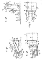
- FIGS. 1 to 6 the illustrated device for producing joints in road surfaces and the like.
- Floor fixings a frame 1, which is by means of a rigid four-wheel chassis on the floor or a road surface or the like.
- the chassis comprises rear wheels 1a arranged on a rear axle and two front wheels 2 which are suspended from the front ends of rigid arms 3 and 4 of the frame 1.
- the wheels of the rear axle 1a are driven in a manner known per se by a feed motor, not shown in detail.
- the boom 3 on the right in the direction of travel of the device is arranged approximately as an extension of the right outer side of the frame 1, while the left arm 4 is arranged from the left outer side of the frame 1 towards the center of the device.
- a handwheel 7 arranged at the top of the device frame 1 on a spindle drive, an adjustment of the rear axle 1a for correcting the direction of the device is possible via a roller chain 6 and a chain wheel 5.
- the device frame 1 In its front area, the device frame 1 has a lower, vertically extending frame part 10 with a bearing block 8 which is pivotally supported on the frame part 10 by means of a pin 9 forming a pivot point.
- the bearing block 8 At the end opposite the bolt 9, in the example shown on the right-hand side of the device in the direction of travel, in this arrangement the bearing block 8 can be pivoted downward from an arch at an acute angle from a horizontal position running parallel to the axes of rotation of the undercarriage wheels .
- the bearing block 8 is provided with an adjusting head 12 which is designed as a nut and extends through an elongated hole 11 in the frame part 10 and which has a threaded spindle 14 which can be actuated by means of a handwheel 13 for a displacement and adjustment of the bearing block between the horizontal position and one in FIG. 3 is in adjustment engagement at 8 'shown in dash-dot lines.
- a rocker 15 (Fig. 4 to 6) is articulated with its pivot axis 16 to the bearing block 8.
- the rocker 15 carries on the top a drive motor 15a for a circular saw blade or a cutting disc 20 which is arranged on a cutting shaft 18 in the front end region of the rocker 15.
- the drive connection from the motor 15a to the cutting shaft 18 takes place in the example shown by means of a V-belt drive 15b.
- the cutting shaft 18 is short and the cutting disk 20 at the free end of the cutting shaft 18 is arranged approximately in the middle of the device, as is characterized by the vertical longitudinal center plane 1b of the device.
- the front rocker area 19 engages over the front wheel 2 on the left in the direction of travel, so that the cutting shaft 18 with its cutting disk 20 can be completely lowered both in the case of vertical and oblique cuts.
- a guide roller 15c is arranged in the front region of the rocker 15 on its underside and provides the rocker 15 with a bottom-side support in the cutting operation.
- the guide roller 15c thus forms a lower stop for the downward pivoting movement of the rocker 15 under the load on the units arranged thereon, in particular the drive motor 15a, and thus also limits the depth of cut of the cutting disc 20. Since the cutting depth of the cutting disc 20 corresponds to that Working conditions must be adjustable, the guide roller 15c is supported on the rocker 15 for height adjustment.
- the guide roller 15c is fastened with its holder to the free end of the piston rod of the piston of a pressure-operated, e.g. hydraulic, working cylinder 15d, but other actuators, e.g. a manually operated spindle drive.
- the front wheels 2 of the device are arranged near the cutting shaft 18 for reasons of stability.
- an additional undercarriage is provided in its center of gravity, which consists of two wheels 21 and 22, which come from an operation in contact with the ground
- Position for moving the device by means of mechanical or pressure medium-actuated actuators in an inoperative position located above the floor level can be moved and fixed in this position, which is taken up by the wheels 21 and 22 in the cutting operation of the cutting disc 20.
- the rocker 15 is supported on the device frame 1 by means of an actuator 17, in the example shown in the form of a pressure-actuated working cylinder. Since the actuator 17 has to perform a lateral movement when adjusting the tilt of the rocker, it is connected to the underside of the rocker 15 on the one hand and the device frame 1 on the other via spherical suspension members or ball joint bearings.
- the pivot axis 16 of the rocker 15 runs parallel to the cutting shaft 18 in all rocker settings and in particular also in the inclined positions of the rocker 15. This is illustrated in particular in FIG. 6, in which the rocker 15 is shown inclined by the design-related maximum inclination angle of, for example, 30 °. This inclination of the entire rocker 15 is carried out by actuating the handwheel 13. With this arrangement and setting, the downward feed movement and the upward movement of the saw blade 20 are directed parallel to the flanks of the saw blade or the cutting disk 20, as is shown in FIG Double arrow 32 is illustrated. This ensures that the penetration and retraction of the cutting disc 20 take place without the risk of jamming and damage to the cutting disc.
- the guide roller 15c is constantly in the rocker 15 on the front supporting ground engagement with the road surface or the like during the cutting operation of the device. Pavement as particular strength from the F. 4 and 6 can be seen. This constant contact with the ground is particularly necessary if the surface of the road surface is uneven.
- the guide roller 15c drives over such unevenness with corresponding entrainment of the cutting disc 20 held on the rocker 15.
- the actuator 17 is decoupled in the cutting operation of the device in such a way that the rocker 15 corresponds to the Movements of the guide roller 15c can perform free pivoting movements relative to the frame 1.
- the guide roller 15c For a normal rolling movement of the guide roller 15c on the surface of the road surface, the guide roller 15c is mounted in a bearing fork which is fastened to the piston rod of the working cylinder 15d and is freely rotatable about an axis 15e. runs parallel to the axes of rotation of the undercarriage wheels of the device, which are designated by 2a in FIGS. 3 and 6 for the front wheels 2.
- the working cylinder 15d is adjustably supported on the rocker 15 in such a way that regardless of the inclined position set for the rocker 15 or the cutting disc 20, the horizontal or parallel position of the axis of rotation 15e of the guide roller 15c to the axes of rotation of the chassis can be set.
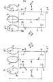
- FIGS. 7 to 10 While cutting vertical joints into a carriageway blanket or the like Fixing the cutting disc to the ground at an angle of 90 ° to the surface of the road surface is illustrated in FIGS. 7 to 10 angular positions or inclinations of the cutting disc 20 which deviate from the .90 ° angle and which are also indicated by a corresponding inclination of the rocker 15 their pivot axis 16 have been brought about in the manner described above. All of the embodiments shown in FIGS. 7 to 10 have in common that the downward feed movement and the upward movement of the cutting disc 20 take place parallel to the cutting disc flanks, so that lateral contact of the cutting disc 20 with the road surface to be cut is avoided.
- Figures 9 and 10 show the device looking towards the front of the device carrying the rocker 15, i.e. against the normal feed and cutting movement. Assuming the view of the operator standing behind the device and looking in the cutting direction, the arrangements shown in FIG. 9 can be referred to as the right-angled positions and the arrangements according to FIG. 10 as the left-angled positions of the saw blade 20 are, these inclinations have been brought about by corresponding inclinations of the pivot axis 16. of the rocker 15.
- FIG. 7 shows a top view of the left-angled cutting disk arrangements according to FIG. 10, while FIG. 8 illustrates the right-angle cutting disk arrangements according to FIG. 9 in a top view.
- the device frame is designated by 61 and 71.
- the rear wheels here designated 62 or 72 and not in driven in more detail, the device receives its normal forward feed movement.
- the front wheels are labeled 63 and 73, respectively.
- 7 and 8 are schematic representations, the cutting shafts. Drive shafts of the cutting discs and their storage not shown.
- the rotation of the cutting disc 20 produces a tangential reaction force F on the circumference of the cutting disc.
- This force acts on the device and can be divided into a vertical component which is irrelevant in the above context and therefore not shown, as well as a horizontally forward component and a horizontal transverse component F. The latter component is of particular importance for the driving behavior and the directional stability of the device.
- the horizontally forward movement component is canceled by a larger rearward force, which is caused by the cutting engagement of the cutting disc 20.
- the rest of this force after subtracting the forward horizontal component is the backward force F v1 .
- the continuous advancement of the device 61 or 71 requires it to be driven and moved forward with a uniform, forward-directed force F.
- the rotary movement of the cutting disc 20 is indicated in FIGS. 7 and 8 by an arrow 65 and 75, respectively.
- embodiments I and V which show simple arrangements of a drive or cutting shaft 92 with a cutting disc 20 by means of ball bearings 94, in which the cutting disc 20 has a left inclination on the left device side (I) and a right inclination on the right device side (V). is arranged with a corresponding Neigunq the cutting shaft 92 to the left or to the right, the forces specified lead to a total torque, which causes a deviation of the device from its straight travel, so that an undesired arcuate Fu g en steel generated and the cutting disc receives pressure from the side resulting in possible damage.
- This total moment consists of the moment M, which is generated by the backward force F v1 and acts on the lever a, and of the moment M, which is generated by the horizontal force component F q and acts on the lever b.
- the sum of both moments rotates the device 61 to the left in the cutting mode of embodiment I and to the right in the same way in the cutting mode of embodiment V.
- a more favorable force ratio results when the cutting disc 20 is arranged with a left inclination on the right side of the device (version II) or instead when the cutting disc 20 is arranged with a right inclination on the left side of the device (version IV).
- the moments M q and M v are opposite to each other and the resulting moment results from a subtraction of the moments.
- both moments are equal, so that the resulting force is O. With easy handling and guidance of the device in the cutting operation, this leads to a straight forward joint cut without any deviations from the straight line.
- a short bearing 102 for the cutting shaft 105 is required, which executes up and down movements in the direction of the double arrow 101.
- the shaft of the V-belt pulley 104 is supported .
- the cutting shaft 105 and the V-belt pulley shaft are in turn connected to one another by two shafts 108 and 111 with bending and ball joints 107 and 109.
- Embodiment IV which, as shown in FIG. 9, has a short bearing arrangement 95 with a cutting shaft 97 and one V-belt pulley 96 used.
- Embodiment IV therefore represents a preferred solution, in which at most the short bearing spacing can lead to high radial loads on the bearings.
- Embodiment III is less preferable in practice, since the V-belt pulley 104 or the like at point 110 even at small depths of cut with the surface of the road surface.
- Floor fixture comes into contact.
- Embodiment VI allows the cutting disc 20 to penetrate into the ground until its clamping flanges 98 almost touch the ground surface.
- a relatively long bearing arrangement 99 can be used to advantage.
- the embodiment VI practically corresponds to the appendix of FIGS. 1 to 6 in the practical embodiment explained in detail and, taking into account the achievable torque compensation and the constructive possibilities, the present. most preferred embodiment.
- the device can also work in reverse with a trailing cutting disc.
Landscapes
- Engineering & Computer Science (AREA)
- Mining & Mineral Resources (AREA)
- Architecture (AREA)
- Civil Engineering (AREA)
- Structural Engineering (AREA)
- Road Repair (AREA)
- Road Paving Structures (AREA)
Applications Claiming Priority (2)
| Application Number | Priority Date | Filing Date | Title |
|---|---|---|---|
| DE3200862 | 1982-01-14 | ||
| DE3200862A DE3200862A1 (de) | 1982-01-14 | 1982-01-14 | Vorrichtung zum herstellen von fugen in strassendecken u. dgl. bodenbefestigungen |
Publications (1)
| Publication Number | Publication Date |
|---|---|
| EP0085304A1 true EP0085304A1 (fr) | 1983-08-10 |
Family
ID=6153009
Family Applications (1)
| Application Number | Title | Priority Date | Filing Date |
|---|---|---|---|
| EP83100153A Withdrawn EP0085304A1 (fr) | 1982-01-14 | 1983-01-11 | Dispositif pour former des joints dans des chaussées et revêtements de sol similaires |
Country Status (4)
| Country | Link |
|---|---|
| EP (1) | EP0085304A1 (fr) |
| DE (1) | DE3200862A1 (fr) |
| DK (1) | DK7383A (fr) |
| NO (1) | NO830082L (fr) |
Cited By (4)
| Publication number | Priority date | Publication date | Assignee | Title |
|---|---|---|---|---|
| EP0169248A1 (fr) * | 1984-06-06 | 1986-01-29 | Alfred Dr. Hackmack | Equipement interchangeable combiné de fraisage et de coupe, joint pour excavateurs, chargeurs, pelles chargeuses, rouleaux compresseurs et tracteurs |
| CN105967117A (zh) * | 2016-06-28 | 2016-09-28 | 林超 | 一种可便捷拆卸型建筑稳定支撑设备 |
| CN114395964A (zh) * | 2022-01-14 | 2022-04-26 | 刘雄军 | 一种便于更换刀具的马路切割机 |
| US12521910B2 (en) | 2022-03-09 | 2026-01-13 | Milwaukee Electric Tool Corporation | Saw cart |
Families Citing this family (10)
| Publication number | Priority date | Publication date | Assignee | Title |
|---|---|---|---|---|
| US4701069A (en) * | 1986-12-10 | 1987-10-20 | Whitney James R | Rain drainage grooves in a road and apparatus for making them |
| DE3642809A1 (de) * | 1986-12-15 | 1988-06-23 | Reinhard Wirtgen | Maschine zum abfraesen oder abschaelen von strassenbelaegen |
| DE4408396A1 (de) * | 1994-03-12 | 1995-09-21 | Mafu Gmbh | Fugenfräse |
| US6499809B1 (en) | 1997-09-30 | 2002-12-31 | Snapper Machinery, Inc. | Apparatus for cutting recesses in pavement |
| US6592289B1 (en) * | 2000-08-29 | 2003-07-15 | Leonard A. Weander | Technique for contraction joints in concrete pavement |
| US7837276B2 (en) | 2006-07-06 | 2010-11-23 | Diamond Surface, Inc. | Close proximity grinder |
| US8821063B2 (en) | 2011-12-01 | 2014-09-02 | Surface Preparation Technologies, Llc | Control system and method for road cutting machine |
| WO2015042226A1 (fr) | 2013-09-20 | 2015-03-26 | Surface Preparation Technologies Llc | Procédé et appareil pour découper une rainure sinusoïdale dans une surface routière |
| US20170211245A1 (en) | 2016-01-21 | 2017-07-27 | Diamond Surface, Inc. | Reduced volume sonic noise alert pattern grinder & method |
| CN108222478B (zh) * | 2016-06-28 | 2020-04-28 | 海门市知舟工业设计有限公司 | 一种可定向转换的建筑支撑辅助设备 |
Citations (5)
| Publication number | Priority date | Publication date | Assignee | Title |
|---|---|---|---|---|
| US2845851A (en) * | 1952-06-03 | 1958-08-05 | Reliance Steel Prod Co | Machine for making anti-skid concrete road surfaces |
| US3007688A (en) * | 1959-10-12 | 1961-11-07 | Concrete Sawing Equipment Inc | Pavement cutting device having aligned abrasive blades |
| CH372696A (fr) * | 1961-11-03 | 1963-10-31 | Sogerep S A | Machine pour scier ou meuler des dalles de béton et d'asphalte |
| US3141702A (en) * | 1962-04-30 | 1964-07-21 | Amos B Barton | Mobile saw for pavement and the like |
| FR1481149A (fr) * | 1966-04-04 | 1967-05-19 | Machine à scier les dalles en béton, et travaux analogues |
-
1982
- 1982-01-14 DE DE3200862A patent/DE3200862A1/de not_active Withdrawn
-
1983
- 1983-01-10 DK DK7383A patent/DK7383A/da not_active Application Discontinuation
- 1983-01-11 EP EP83100153A patent/EP0085304A1/fr not_active Withdrawn
- 1983-01-12 NO NO830082A patent/NO830082L/no unknown
Patent Citations (5)
| Publication number | Priority date | Publication date | Assignee | Title |
|---|---|---|---|---|
| US2845851A (en) * | 1952-06-03 | 1958-08-05 | Reliance Steel Prod Co | Machine for making anti-skid concrete road surfaces |
| US3007688A (en) * | 1959-10-12 | 1961-11-07 | Concrete Sawing Equipment Inc | Pavement cutting device having aligned abrasive blades |
| CH372696A (fr) * | 1961-11-03 | 1963-10-31 | Sogerep S A | Machine pour scier ou meuler des dalles de béton et d'asphalte |
| US3141702A (en) * | 1962-04-30 | 1964-07-21 | Amos B Barton | Mobile saw for pavement and the like |
| FR1481149A (fr) * | 1966-04-04 | 1967-05-19 | Machine à scier les dalles en béton, et travaux analogues |
Cited By (6)
| Publication number | Priority date | Publication date | Assignee | Title |
|---|---|---|---|---|
| EP0169248A1 (fr) * | 1984-06-06 | 1986-01-29 | Alfred Dr. Hackmack | Equipement interchangeable combiné de fraisage et de coupe, joint pour excavateurs, chargeurs, pelles chargeuses, rouleaux compresseurs et tracteurs |
| CN105967117A (zh) * | 2016-06-28 | 2016-09-28 | 林超 | 一种可便捷拆卸型建筑稳定支撑设备 |
| CN105967117B (zh) * | 2016-06-28 | 2018-08-10 | 浙江森海建设有限公司 | 一种可便捷拆卸型建筑稳定支撑设备 |
| CN114395964A (zh) * | 2022-01-14 | 2022-04-26 | 刘雄军 | 一种便于更换刀具的马路切割机 |
| CN114395964B (zh) * | 2022-01-14 | 2024-05-31 | 山东金鑫机械有限公司 | 一种便于更换刀具的马路切割机 |
| US12521910B2 (en) | 2022-03-09 | 2026-01-13 | Milwaukee Electric Tool Corporation | Saw cart |
Also Published As
| Publication number | Publication date |
|---|---|
| DE3200862A1 (de) | 1983-07-21 |
| DK7383A (da) | 1983-07-15 |
| NO830082L (no) | 1983-07-15 |
| DK7383D0 (da) | 1983-01-10 |
Similar Documents
| Publication | Publication Date | Title |
|---|---|---|
| DE2364028A1 (de) | Maschine zur bearbeitung von strassenoberflaechen | |
| EP0085304A1 (fr) | Dispositif pour former des joints dans des chaussées et revêtements de sol similaires | |
| EP0310074B1 (fr) | Dispositif de fraisage destiné à être monté à un appareil mobile | |
| DE3025312A1 (de) | Spur- oder planiergeraet fuer ski-loipen bzw. pisten | |
| DE102007060215A1 (de) | Vorrichtung zum Bearbeiten einer Fahrkante | |
| AT403812B (de) | Maschine zum anpressen von schwellenankern | |
| DE2156282A1 (de) | Maschine zum schicht weisen Abtragen, insbesondere verschlissener Straßendecken | |
| EP0367951B1 (fr) | Fraiseuse pour écarter l'asphalte ou le béton de pavage le long d'un contour quelconque | |
| DE3127856C2 (fr) | ||
| EP2295642A2 (fr) | Fraiseuse routière | |
| DE9406572U1 (de) | Fahrwerk, insbesondere für mobile Arbeitsgeräte und Fahrzeuge | |
| DE3802584C1 (en) | Excavator | |
| DE8812328U1 (de) | An ein fahrbares Tragwerk anbaubare Fräse | |
| DE19531952C2 (de) | Fugenschneideeinrichtung für Längs- und Querfugen | |
| DE8200660U1 (de) | Vorrichtung zum herstellen von fugen in strassendecken u. dgl. bodenbefestigungen | |
| AT395877B (de) | Einrichtung zum aufrauhen und einebnen einer mit hartschnee bedeckten und/oder vereisten verkehrsflaeche | |
| DE2430215A1 (de) | Verfahrbarer lagerrahmen fuer schwere maschinen oder anlagen | |
| DE2919154C2 (de) | Vorrichtung zur Bearbeitung von Straßenbelägen | |
| DE2264710C3 (fr) | ||
| DE2209829C3 (de) | Fahrbare Straßenbearbeitungsmaschine | |
| DE3615996C2 (de) | Vorrichtung zum Einebnen und Verdichten von Schüttgütern | |
| CH587386A5 (fr) | ||
| DE8714999U1 (de) | Verfahrbarer Fugenschneider, insbesondere zur Herstellung von Schnitten in Straßendecken | |
| DE1634636C2 (de) | Fahrbarer Rammwagen, insbesondere zum Rammen von parallelen Spundwänden | |
| DE2040890C3 (de) | Maschine zum Einschneiden von lütten in Fahr- oder Rollbahnoberflächen |
Legal Events
| Date | Code | Title | Description |
|---|---|---|---|
| PUAI | Public reference made under article 153(3) epc to a published international application that has entered the european phase |
Free format text: ORIGINAL CODE: 0009012 |
|
| AK | Designated contracting states |
Designated state(s): AT CH FR GB IT LI NL SE |
|
| STAA | Information on the status of an ep patent application or granted ep patent |
Free format text: STATUS: THE APPLICATION IS DEEMED TO BE WITHDRAWN |
|
| 18D | Application deemed to be withdrawn |
Effective date: 19840411 |
|
| RIN1 | Information on inventor provided before grant (corrected) |
Inventor name: OSTERTAG, ALFRED |