EP0085341B1 - Verstellbares Geländersystem - Google Patents
Verstellbares Geländersystem Download PDFInfo
- Publication number
- EP0085341B1 EP0085341B1 EP83100364A EP83100364A EP0085341B1 EP 0085341 B1 EP0085341 B1 EP 0085341B1 EP 83100364 A EP83100364 A EP 83100364A EP 83100364 A EP83100364 A EP 83100364A EP 0085341 B1 EP0085341 B1 EP 0085341B1
- Authority
- EP
- European Patent Office
- Prior art keywords
- rail
- socket
- pivot
- baluster
- recess
- Prior art date
- Legal status (The legal status is an assumption and is not a legal conclusion. Google has not performed a legal analysis and makes no representation as to the accuracy of the status listed.)
- Expired
Links
- 238000000465 moulding Methods 0.000 claims description 31
- 238000000034 method Methods 0.000 claims description 9
- 239000011295 pitch Substances 0.000 abstract description 7
- 238000009434 installation Methods 0.000 description 15
- 238000004519 manufacturing process Methods 0.000 description 4
- 238000010276 construction Methods 0.000 description 3
- 239000002023 wood Substances 0.000 description 2
- 230000015572 biosynthetic process Effects 0.000 description 1
- 238000005755 formation reaction Methods 0.000 description 1
- 239000000463 material Substances 0.000 description 1
- 238000003801 milling Methods 0.000 description 1
- 230000000717 retained effect Effects 0.000 description 1
Images


Classifications
-
- E—FIXED CONSTRUCTIONS
- E04—BUILDING
- E04F—FINISHING WORK ON BUILDINGS, e.g. STAIRS, FLOORS
- E04F11/00—Stairways, ramps, or like structures; Balustrades; Handrails
- E04F11/18—Balustrades; Handrails
- E04F11/181—Balustrades
- E04F11/1817—Connections therefor
- E04F11/1834—Connections therefor with adjustable angle, e.g. pivotal connections
-
- Y—GENERAL TAGGING OF NEW TECHNOLOGICAL DEVELOPMENTS; GENERAL TAGGING OF CROSS-SECTIONAL TECHNOLOGIES SPANNING OVER SEVERAL SECTIONS OF THE IPC; TECHNICAL SUBJECTS COVERED BY FORMER USPC CROSS-REFERENCE ART COLLECTIONS [XRACs] AND DIGESTS
- Y10—TECHNICAL SUBJECTS COVERED BY FORMER USPC
- Y10S—TECHNICAL SUBJECTS COVERED BY FORMER USPC CROSS-REFERENCE ART COLLECTIONS [XRACs] AND DIGESTS
- Y10S256/00—Fences
- Y10S256/02—Adjustable or falling fence
-
- Y—GENERAL TAGGING OF NEW TECHNOLOGICAL DEVELOPMENTS; GENERAL TAGGING OF CROSS-SECTIONAL TECHNOLOGIES SPANNING OVER SEVERAL SECTIONS OF THE IPC; TECHNICAL SUBJECTS COVERED BY FORMER USPC CROSS-REFERENCE ART COLLECTIONS [XRACs] AND DIGESTS
- Y10—TECHNICAL SUBJECTS COVERED BY FORMER USPC
- Y10T—TECHNICAL SUBJECTS COVERED BY FORMER US CLASSIFICATION
- Y10T403/00—Joints and connections
- Y10T403/33—Transverse rod to spaced plate surfaces
- Y10T403/335—Retainer utilizes or abuts plural plates
Definitions
- This invention relates generally to rail and baluster systems, and more particularly concerns adjustable railing sections in systems wherein balusters and rails are angularly adjustable after their assembly to fit the different pitches of stairways, as defined in the precharacterizing part of claim 1.
- balusters and rails Conventional installation of balusters and rails is undesirably time consuming as respects cutting balusters to proper angle and length, attaching them to the rails, and filling in the gaps with fillet pieces which must also be cut to length and angle and attached. Due to this conventional installation difficulty, pre-assembled systems have been developed which do not require cutting of balusters, but do not require cutting and installation of fillets.
- stair systems whether of conventional or variable pitch, are that they require balusters with squared ends to fit into rail plow.
- stairs use two sizes of wood stock which they are all turned on a lathe. These are usually 4.13 cm (1-5/8") or 3.18 cm (1-1/4") squared end pieces, and must also have rails with proper size plow-different rails for different size balusters. Since homeowners may prefer the thinner or thicker appearing balusters, the industry produces and stocks both sizes of balusters and double inventory of railing.
- the current pre-assembled variable pitch systems must be sold in a variety of specific lengths for various installations.
- U.S. Patent No. 4,138,094 discloses a concept of longitudinally sliding an interior rail, carrying baluster pivots, into an exterior rail. This assembly of a two-piece rail can be difficult and time-consuming.
- the present invention avoids such difficulties by providing the claimed simple one-piece rail construction, wherein the rail has an elongated recess sunk into one exterior lateral side thereof, with a socket laterally intersecting the recess to laterally receive a baluster pivot, the socket curve wall being one piece with the rail.
- the recess has L-shaped interior sides which are laterally exposed to the exterior, to laterally receive and confine an exterior molding fitting to the rail, thereby to laterally confine the baluster pivot.
- the improved rail of the invention is an adjustable railing section comprising a rail and at least one baluster having a pivot at at least one end thereof, said pivot being configured to be received in a socket formed in said rail, characterized by a) the rail being in one piece and having an elongated recess sunk in one exterior lateral side thereof; and having at least one said interior socket laterally intersecting said recess; b) the socket having a curved wall and an interior laterally facing wall defined by the rail, said curved wall and said laterally facing wall being of one-piece with the rail; and c) the recess having L-shaped interior sides that receive and confine an exterior moulding fitting to the rail which laterally confines the pivot in the socket between the moulding and said interior wall, thus providing pivoting in said socket, said L-shaped interior sides being laterally exposed to the exterior.
- the present invention also provides for in the method of forming a connection between a one-piece rail and at least one baluster having a pivot at the end thereof, and employing an elongated moulding, the steps that include: a) forming an elongated recess in one exterior lateral side of the rail, thereby to provide an interior laterally facing wall; b) forming at least one socket having a curved wall in said interior wall, and causing said socket to intersect a baluster side of the rail with an opening at the intersection; c) placing a baluster pivot in the socket so that the baluster projects through said opening; and d) placing said moulding in said recess to confine the pivot in said socket, and adhering the moulding to the rail.
- the baluster pivot typically has a spherical or partly spherical outer surface to facilitate ease and rapidity of installation into a pre-formed socket;
- the recess in the rail has L-shaped interior sides into a lateral one of which the socket is sunk, so as also to intersect the rail outerside facing the baluster to form an opening, whereby the baluster pivot may be sidewardly placed into the socket with the baluster protruding through the opening; and the pivot may be pivotally confined in the socket simply by placing a single moulding in the recess and adhering the moulding to the rail. Accordingly, no sliding of rail to rail is required, as in the Thir patent. Also, the structure is especially well adapted to wooden rail manufacturing processes.
- the invention also enables ready removal and replacement of installed balusters, as will be seen.
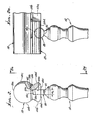
- upper and lower rails 10 and 11 are interconnected by balusters 12.
- Such rails and balusters may consist of wood or other materials.
- Rail 10 has upper side 10a, laterally opposite sides 10b and 10c, and a bottom side 10d from which the balusters protrude.
- lower rail 11 has a lower side 11a attachable to stairway or other structure, laterally opposite sides 11b and 11c, and an upper side 11d from which balusters 12 protrude.
- the upper rail 10 has an elongated recess 13 . sunk in its lateral side 10c, and also intersecting rail side 10d as well.
- the recess may typically have or be bounded by L-shaped interior walls 13a and 13b, the former facing laterally and the latter downwardly. As a consequence, the recess may easily be cut into the rail as by a milling cutter.
- the rail 10 also has at least one, and normally at number of interior sockets 14 formed therein at intervals spaced along the rail corresponding to baluster intervals and sunk into interior wall 13a.
- Each socket 14 is typically cylindrical, but with a lateral axis 15 spaced closer to the bottom side 10d than the socket radius dimension.
- the axis 15 is generally normal to a vertical plane 15a bisecting the rail. Socket cylindrical inner wall appears at 14c.
- the socket intersects the bottom side 10dto form a rectangular opening 16 therein, that opening having a width "w / ' the same as the socket depth, and a length "I" which is between about 9/8 r and 15/8 r, where "r" is the socket radius.
- the angle a subtended by radii extending from the axis 15 to the ends 16a and 17 of the rectangular opening is typically between about 100° and 170°. This allows for wide angular adjustment of the balusters and rails, during installation of a rail and baluster system, as adjacent a stairway as will be seen.
- the socket is configured to receive a pivot at the end of a baluster, with the baluster projecting from the rail; and in addition, each recess is configured to receive a molding to be removably or permanently attached to the rail so as to laterally confine the pivot in the socket, while accommodating adjustment pivoting thereof.
- the pivot 20 is shown as having shape to fit the socket, with opposite flat sides 20a and 20b, and a spherical outer surface 20c, that merges with a baluster neck 21.
- the width "002" of the pivot is substantially less than the length "I" of the opening 16, and slightly less than the width ⁇ of that opening.
- the outer diameter of the pivot is approximately the same as the diameter of the socket, having a snug fit therewith when lightly pressed into the socket.
- the spherical curvature of interrupted surface 20c facilitates ease of assembly of the pivot into the socket despite small variances in dimension occurring in production.
- Elongated molding 23 is receivable in the recess and attached to the rail to closely confine the pivot for adjustable rotation in the socket between socket inner flat wall 14a and molding inner flat wall 23a. Such adjustment allows relative rotation of the baluster and railing through an angle ⁇ shown in Figure 1, as during installation of the railing and baluster system.
- the moulding also has a wall 23b extending at 90° to wall 23a and L-shaped walls 23a and 23b may for example be adhesively bonded to rail recess L-shaped walls 13a and 13b respectively.
- moulding bottom side 23c may form a continuation of rail bottom side 10d, as shown, and the molding, lateral side 23d may conform in outline to the extent 10b' of lateral side 10b.
- FIG. 4 shows that cylindrical pivots 120 at the opposite ends of the balusters, and like pivots 20, are similarly retained in bottom rail sockets 114 by moulding 123, like moulding 23, the construction being generally the same. Note spherical surface 120c of pivot 120.
- FIG. 1 a method and means of attaching the baluster at the end of the rail to a post 60 is shown.
- a nail or other fastener 61 is inserted into position, projecting from proximate the intersection 13c of recess walls 13a and 13b angularly through the end 10f of the rail, and into the post 60, and for concealment. Other methods may be used.
- the invention facilitates ease of removal and replacement of installed balusters, as follows: the moulding 23 is first removed, as by removing nails holding the moulding to the rail. (see removable nails 62 in Figure 2). The pivots may then be popped out of their sockets, due to very low frictional resistance between spherical surfaces 20c and socket cylindrical walls 14c. A new baluster or balusters may then be inserted, and moulding 23 replaced. Accordingly, broken balusters may be replaced, and new design or style balusters may be employed, as required for redecoration purposes.
- FIGS 6 and 7 show a baluster 112 with a modified, i.e. thicker pivot 220, having spherical surface 220c intersecting parallel flat sides 220a and 220b.
Landscapes
- Engineering & Computer Science (AREA)
- Architecture (AREA)
- Civil Engineering (AREA)
- Structural Engineering (AREA)
- Steps, Ramps, And Handrails (AREA)
- Bridges Or Land Bridges (AREA)
- Non-Portable Lighting Devices Or Systems Thereof (AREA)
- Polymerisation Methods In General (AREA)
- Escalators And Moving Walkways (AREA)
Claims (10)
Priority Applications (1)
| Application Number | Priority Date | Filing Date | Title |
|---|---|---|---|
| AT83100364T ATE23897T1 (de) | 1982-01-18 | 1983-01-17 | Verstellbares gelaendersystem. |
Applications Claiming Priority (2)
| Application Number | Priority Date | Filing Date | Title |
|---|---|---|---|
| US06/339,877 US4408749A (en) | 1982-01-18 | 1982-01-18 | Variable pitch railing and system |
| US339877 | 1982-01-18 |
Publications (2)
| Publication Number | Publication Date |
|---|---|
| EP0085341A1 EP0085341A1 (de) | 1983-08-10 |
| EP0085341B1 true EP0085341B1 (de) | 1986-11-26 |
Family
ID=23331012
Family Applications (1)
| Application Number | Title | Priority Date | Filing Date |
|---|---|---|---|
| EP83100364A Expired EP0085341B1 (de) | 1982-01-18 | 1983-01-17 | Verstellbares Geländersystem |
Country Status (5)
| Country | Link |
|---|---|
| US (1) | US4408749A (de) |
| EP (1) | EP0085341B1 (de) |
| AT (1) | ATE23897T1 (de) |
| CA (1) | CA1197403A (de) |
| DE (1) | DE3367948D1 (de) |
Families Citing this family (27)
| Publication number | Priority date | Publication date | Assignee | Title |
|---|---|---|---|---|
| GB8333051D0 (en) * | 1983-12-10 | 1984-01-18 | Sinclair A A | Bolt system |
| US4505456A (en) * | 1984-03-12 | 1985-03-19 | Mansion Industries, Inc. | Railing and baluster connection |
| GB8616405D0 (en) * | 1986-07-04 | 1986-08-13 | Northern Joinery Ltd | Balustrades |
| DE3634901A1 (de) * | 1986-10-14 | 1988-04-28 | Neucon Masch Bausystem | Treppenhandlauf |
| US4886245A (en) * | 1987-01-20 | 1989-12-12 | Louis Manzo | Interlocking pivot device for adjustable ballusters |
| US4928930A (en) * | 1989-11-02 | 1990-05-29 | Chung Yu Kuei | Balustrade |
| US5056283A (en) * | 1990-06-06 | 1991-10-15 | Visador Company | Adjustable stair rail |
| AU3638993A (en) * | 1992-02-27 | 1993-09-13 | Ellis Hawkins Limited | Joints and methods of making them |
| FR2713723B1 (fr) * | 1993-12-10 | 1996-01-12 | Schutt Ferronniers Art Sa | Dispositif d'assemblage, en particulier pour éléments creux de garde-corps ou analogue. |
| FR2723978A1 (fr) * | 1994-08-30 | 1996-03-01 | Escalier Bois Marcel Beck Sa L | Escalier a rampe |
| US5557893A (en) * | 1995-07-27 | 1996-09-24 | Bowls; George A. | Adjustable pitch spiral stairway kit |
| DE29707890U1 (de) | 1997-05-02 | 1998-09-03 | HEWI Heinrich Wilke GmbH, 34454 Bad Arolsen | Vorrichtung zur Befestigung eines Handlaufelements an einem Pfosten, insbesondere zur Herstellung eines Treppengeländers, und Bausatz dafür |
| US6231031B1 (en) * | 1999-02-11 | 2001-05-15 | Spartanburg Forest Products, Inc. | Outdoor railing system and rails |
| USD484249S1 (en) | 1999-11-09 | 2003-12-23 | Spartanburg Forest Products, Inc. | Top or bottom rail for outdoor railing systems |
| USD468443S1 (en) | 1999-11-09 | 2003-01-07 | Spartanburg Forest Products, Inc. | Top or bottom rail for outdoor railing systems |
| USD454960S1 (en) | 1999-11-09 | 2002-03-26 | Spartanburg Forest Products, Inc. | Surface of a top or bottom rail for outdoor railing systems |
| CA2493003A1 (en) * | 2005-01-31 | 2006-07-31 | Stanley M. Paskar | Pre-fabricated fencing panels |
| GB2431940A (en) * | 2005-11-07 | 2007-05-09 | Palgrave Brown Uk Ltd | Balustrading kit and method |
| US20080283811A1 (en) * | 2005-12-05 | 2008-11-20 | Johnstonbaugh G Stephen | Railing assembly |
| US7913983B1 (en) | 2006-11-13 | 2011-03-29 | Sandor Sr Frederick J | Stair, ramp, or balcony railing system |
| US7614612B2 (en) * | 2007-01-23 | 2009-11-10 | Carolina Stair Supply, Inc. | Adjustable baluster system |
| US20090064607A1 (en) * | 2007-09-06 | 2009-03-12 | Howard Katz | Adjustable stair rail |
| US20090127533A1 (en) * | 2009-01-16 | 2009-05-21 | Glenn Gorab | Dual use wall mounted child safety banister |
| US8936233B1 (en) * | 2012-02-20 | 2015-01-20 | Jayme M. Sneith | Baluster bracket assembly |
| USD733324S1 (en) * | 2013-12-05 | 2015-06-30 | Inpro Corporation | Handrail |
| US20150252570A1 (en) * | 2014-03-05 | 2015-09-10 | Russell H. Springborn | Swivel connector |
| US10081949B2 (en) | 2015-06-26 | 2018-09-25 | Jad Honein | Interchangeable bracket flange system |
Family Cites Families (13)
| Publication number | Priority date | Publication date | Assignee | Title |
|---|---|---|---|---|
| DE259042C (de) * | ||||
| DE23698C (de) * | C. DlETZ in Brüssel | Drehbarer und verschiebbarer Belastungshebel für Bufferfeder - Maschinen | ||
| US263324A (en) * | 1882-08-29 | Iron fence | ||
| US699509A (en) * | 1902-01-30 | 1902-05-06 | Thomas Devlin & Co | Coupling for railings, &c. |
| US3004751A (en) * | 1960-04-18 | 1961-10-17 | William H Woodward | Handrail mounting |
| US3306586A (en) * | 1965-07-13 | 1967-02-28 | George E Green | Adjustable railing |
| DE1659865A1 (de) * | 1967-12-19 | 1970-04-16 | Theodor Fischer | Handlauf fuer Treppengelaender |
| US3995832A (en) * | 1973-10-10 | 1976-12-07 | Harold Wiese | Collapsible bleacher rail |
| FR2372287A1 (fr) * | 1976-11-26 | 1978-06-23 | Berthet Bondet Raymonde | Procede de fabrication d'escaliers complets adaptables a des pentes variables et escaliers fabriques selon ce procede |
| US4138094A (en) * | 1977-03-31 | 1979-02-06 | Peter Thir | Adjustable railing assembly |
| JPS54154124A (en) | 1978-05-26 | 1979-12-05 | Naka Tech Lab | Handrail |
| US4272061A (en) * | 1979-11-28 | 1981-06-09 | Suckno Brothers Company | Variable pitch rail system |
| BE883102A (fr) * | 1980-05-02 | 1980-11-03 | Jacob Fernande | Fuseau de rampe d'escalier a fixation variable pour la main-courante |
-
1982
- 1982-01-18 US US06/339,877 patent/US4408749A/en not_active Expired - Lifetime
-
1983
- 1983-01-11 CA CA000419246A patent/CA1197403A/en not_active Expired
- 1983-01-17 EP EP83100364A patent/EP0085341B1/de not_active Expired
- 1983-01-17 DE DE8383100364T patent/DE3367948D1/de not_active Expired
- 1983-01-17 AT AT83100364T patent/ATE23897T1/de active
Also Published As
| Publication number | Publication date |
|---|---|
| EP0085341A1 (de) | 1983-08-10 |
| ATE23897T1 (de) | 1986-12-15 |
| CA1197403A (en) | 1985-12-03 |
| US4408749A (en) | 1983-10-11 |
| DE3367948D1 (en) | 1987-01-15 |
Similar Documents
| Publication | Publication Date | Title |
|---|---|---|
| EP0085341B1 (de) | Verstellbares Geländersystem | |
| US4505456A (en) | Railing and baluster connection | |
| US5823724A (en) | End caps for tie-down track and process for installing a tie-down track | |
| US6494438B1 (en) | Plastic porch or deck railing systems and component parts thereof | |
| US6293523B1 (en) | Angle adjustable retaining wall and fencing system | |
| US4421302A (en) | Prefabricated adjustable handrail assembly | |
| US4272061A (en) | Variable pitch rail system | |
| US6736366B2 (en) | Extruded plastic bulkhead device for forming concrete panels | |
| US7775014B2 (en) | Method and arrangement for studsystem | |
| US6453538B1 (en) | Outdoor railing system and rails | |
| US5513437A (en) | Dovetail tenon offset caliper and dovetail tenon construction method | |
| US20180002948A1 (en) | Decorative railing with adjustable attaching block | |
| EP0251826A2 (de) | Geländer | |
| US4599779A (en) | Construction tool | |
| EP0246057A2 (de) | Einrast-Spindeleinrichtung für einstellbare Geländersäulen | |
| US6164629A (en) | Outdoor railing system and rails | |
| US5383739A (en) | Variable angle post for coupling fence segments | |
| CA1258984A (en) | Screw driver tip | |
| US4154032A (en) | Stairs and method of making the same | |
| US20090016815A1 (en) | Hand rail return construction | |
| US20040083664A1 (en) | Baseboard assembly and trim | |
| AU682591B2 (en) | Cladding board | |
| US12584355B2 (en) | Track assembly system | |
| JPS597946Y2 (ja) | 手すり子取付構造 | |
| JPH09273283A (ja) | 連結形手摺 |
Legal Events
| Date | Code | Title | Description |
|---|---|---|---|
| PUAI | Public reference made under article 153(3) epc to a published international application that has entered the european phase |
Free format text: ORIGINAL CODE: 0009012 |
|
| AK | Designated contracting states |
Designated state(s): AT BE CH DE FR GB IT LI LU NL SE |
|
| 17P | Request for examination filed |
Effective date: 19840112 |
|
| GRAA | (expected) grant |
Free format text: ORIGINAL CODE: 0009210 |
|
| AK | Designated contracting states |
Kind code of ref document: B1 Designated state(s): AT BE CH DE FR GB IT LI LU NL SE |
|
| PG25 | Lapsed in a contracting state [announced via postgrant information from national office to epo] |
Ref country code: NL Effective date: 19861126 Ref country code: LI Effective date: 19861126 Ref country code: IT Free format text: LAPSE BECAUSE OF FAILURE TO SUBMIT A TRANSLATION OF THE DESCRIPTION OR TO PAY THE FEE WITHIN THE PRESCRIBED TIME-LIMIT;WARNING: LAPSES OF ITALIAN PATENTS WITH EFFECTIVE DATE BEFORE 2007 MAY HAVE OCCURRED AT ANY TIME BEFORE 2007. THE CORRECT EFFECTIVE DATE MAY BE DIFFERENT FROM THE ONE RECORDED. Effective date: 19861126 Ref country code: FR Free format text: THE PATENT HAS BEEN ANNULLED BY A DECISION OF A NATIONAL AUTHORITY Effective date: 19861126 Ref country code: CH Effective date: 19861126 Ref country code: BE Effective date: 19861126 Ref country code: AT Effective date: 19861126 |
|
| REF | Corresponds to: |
Ref document number: 23897 Country of ref document: AT Date of ref document: 19861215 Kind code of ref document: T |
|
| PG25 | Lapsed in a contracting state [announced via postgrant information from national office to epo] |
Ref country code: SE Effective date: 19861130 |
|
| REF | Corresponds to: |
Ref document number: 3367948 Country of ref document: DE Date of ref document: 19870115 |
|
| PG25 | Lapsed in a contracting state [announced via postgrant information from national office to epo] |
Ref country code: LU Free format text: LAPSE BECAUSE OF NON-PAYMENT OF DUE FEES Effective date: 19870131 |
|
| REG | Reference to a national code |
Ref country code: CH Ref legal event code: PL |
|
| EN | Fr: translation not filed | ||
| NLV1 | Nl: lapsed or annulled due to failure to fulfill the requirements of art. 29p and 29m of the patents act | ||
| PLBE | No opposition filed within time limit |
Free format text: ORIGINAL CODE: 0009261 |
|
| STAA | Information on the status of an ep patent application or granted ep patent |
Free format text: STATUS: NO OPPOSITION FILED WITHIN TIME LIMIT |
|
| 26N | No opposition filed | ||
| PGFP | Annual fee paid to national office [announced via postgrant information from national office to epo] |
Ref country code: DE Payment date: 19891220 Year of fee payment: 8 |
|
| PG25 | Lapsed in a contracting state [announced via postgrant information from national office to epo] |
Ref country code: DE Effective date: 19911001 |
|
| PGFP | Annual fee paid to national office [announced via postgrant information from national office to epo] |
Ref country code: GB Payment date: 19941228 Year of fee payment: 13 |
|
| PG25 | Lapsed in a contracting state [announced via postgrant information from national office to epo] |
Ref country code: GB Effective date: 19960117 |
|
| GBPC | Gb: european patent ceased through non-payment of renewal fee |
Effective date: 19960117 |