EP0085354A2 - Outil d'alésage de trous profonds - Google Patents
Outil d'alésage de trous profonds Download PDFInfo
- Publication number
- EP0085354A2 EP0085354A2 EP83100425A EP83100425A EP0085354A2 EP 0085354 A2 EP0085354 A2 EP 0085354A2 EP 83100425 A EP83100425 A EP 83100425A EP 83100425 A EP83100425 A EP 83100425A EP 0085354 A2 EP0085354 A2 EP 0085354A2
- Authority
- EP
- European Patent Office
- Prior art keywords
- drilling
- tool
- pipe
- deep
- pipe section
- Prior art date
- Legal status (The legal status is an assumption and is not a legal conclusion. Google has not performed a legal analysis and makes no representation as to the accuracy of the status listed.)
- Withdrawn
Links
- 238000005553 drilling Methods 0.000 claims abstract description 67
- 238000000034 method Methods 0.000 claims description 9
- 238000007789 sealing Methods 0.000 claims description 6
- 239000002826 coolant Substances 0.000 claims 1
- 238000010276 construction Methods 0.000 description 2
- 239000005068 cooling lubricant Substances 0.000 description 2
- 238000011161 development Methods 0.000 description 2
- 230000018109 developmental process Effects 0.000 description 2
- 230000006978 adaptation Effects 0.000 description 1
- 210000000078 claw Anatomy 0.000 description 1
- 210000004907 gland Anatomy 0.000 description 1
- 125000006850 spacer group Chemical group 0.000 description 1
- 230000007704 transition Effects 0.000 description 1
Images
Classifications
-
- B—PERFORMING OPERATIONS; TRANSPORTING
- B23—MACHINE TOOLS; METAL-WORKING NOT OTHERWISE PROVIDED FOR
- B23Q—DETAILS, COMPONENTS, OR ACCESSORIES FOR MACHINE TOOLS, e.g. ARRANGEMENTS FOR COPYING OR CONTROLLING; MACHINE TOOLS IN GENERAL CHARACTERISED BY THE CONSTRUCTION OF PARTICULAR DETAILS OR COMPONENTS; COMBINATIONS OR ASSOCIATIONS OF METAL-WORKING MACHINES, NOT DIRECTED TO A PARTICULAR RESULT
- B23Q1/00—Members which are comprised in the general build-up of a form of machine, particularly relatively large fixed members
- B23Q1/0009—Energy-transferring means or control lines for movable machine parts; Control panels or boxes; Control parts
- B23Q1/0018—Energy-transferring means or control lines for movable machine parts; Control panels or boxes; Control parts comprising hydraulic means
- B23Q1/0027—Energy-transferring means or control lines for movable machine parts; Control panels or boxes; Control parts comprising hydraulic means between moving parts between which an uninterrupted energy-transfer connection is maintained
- B23Q1/0036—Energy-transferring means or control lines for movable machine parts; Control panels or boxes; Control parts comprising hydraulic means between moving parts between which an uninterrupted energy-transfer connection is maintained one of those parts being a tool
-
- B—PERFORMING OPERATIONS; TRANSPORTING
- B23—MACHINE TOOLS; METAL-WORKING NOT OTHERWISE PROVIDED FOR
- B23B—TURNING; BORING
- B23B41/00—Boring or drilling machines or devices specially adapted for particular work; Accessories specially adapted therefor
- B23B41/02—Boring or drilling machines or devices specially adapted for particular work; Accessories specially adapted therefor for boring deep holes; Trepanning, e.g. of gun or rifle barrels
-
- B—PERFORMING OPERATIONS; TRANSPORTING
- B23—MACHINE TOOLS; METAL-WORKING NOT OTHERWISE PROVIDED FOR
- B23B—TURNING; BORING
- B23B51/00—Tools for drilling machines
- B23B51/04—Drills for trepanning
- B23B51/0486—Drills for trepanning with lubricating or cooling equipment
-
- B—PERFORMING OPERATIONS; TRANSPORTING
- B23—MACHINE TOOLS; METAL-WORKING NOT OTHERWISE PROVIDED FOR
- B23Q—DETAILS, COMPONENTS, OR ACCESSORIES FOR MACHINE TOOLS, e.g. ARRANGEMENTS FOR COPYING OR CONTROLLING; MACHINE TOOLS IN GENERAL CHARACTERISED BY THE CONSTRUCTION OF PARTICULAR DETAILS OR COMPONENTS; COMBINATIONS OR ASSOCIATIONS OF METAL-WORKING MACHINES, NOT DIRECTED TO A PARTICULAR RESULT
- B23Q11/00—Accessories fitted to machine tools for keeping tools or parts of the machine in good working condition or for cooling work; Safety devices specially combined with or arranged in, or specially adapted for use in connection with, machine tools
- B23Q11/08—Protective coverings for parts of machine tools; Splash guards
- B23Q11/0875—Wipers for clearing foreign matter from slideways or slidable coverings
-
- F—MECHANICAL ENGINEERING; LIGHTING; HEATING; WEAPONS; BLASTING
- F16—ENGINEERING ELEMENTS AND UNITS; GENERAL MEASURES FOR PRODUCING AND MAINTAINING EFFECTIVE FUNCTIONING OF MACHINES OR INSTALLATIONS; THERMAL INSULATION IN GENERAL
- F16J—PISTONS; CYLINDERS; SEALINGS
- F16J15/00—Sealings
- F16J15/46—Sealings with packing ring expanded or pressed into place by fluid pressure, e.g. inflatable packings
- F16J15/48—Sealings with packing ring expanded or pressed into place by fluid pressure, e.g. inflatable packings influenced by the pressure within the member to be sealed
-
- Y—GENERAL TAGGING OF NEW TECHNOLOGICAL DEVELOPMENTS; GENERAL TAGGING OF CROSS-SECTIONAL TECHNOLOGIES SPANNING OVER SEVERAL SECTIONS OF THE IPC; TECHNICAL SUBJECTS COVERED BY FORMER USPC CROSS-REFERENCE ART COLLECTIONS [XRACs] AND DIGESTS
- Y10—TECHNICAL SUBJECTS COVERED BY FORMER USPC
- Y10T—TECHNICAL SUBJECTS COVERED BY FORMER US CLASSIFICATION
- Y10T408/00—Cutting by use of rotating axially moving tool
- Y10T408/44—Cutting by use of rotating axially moving tool with means to apply transient, fluent medium to work or product
-
- Y—GENERAL TAGGING OF NEW TECHNOLOGICAL DEVELOPMENTS; GENERAL TAGGING OF CROSS-SECTIONAL TECHNOLOGIES SPANNING OVER SEVERAL SECTIONS OF THE IPC; TECHNICAL SUBJECTS COVERED BY FORMER USPC CROSS-REFERENCE ART COLLECTIONS [XRACs] AND DIGESTS
- Y10—TECHNICAL SUBJECTS COVERED BY FORMER USPC
- Y10T—TECHNICAL SUBJECTS COVERED BY FORMER US CLASSIFICATION
- Y10T408/00—Cutting by use of rotating axially moving tool
- Y10T408/44—Cutting by use of rotating axially moving tool with means to apply transient, fluent medium to work or product
- Y10T408/45—Cutting by use of rotating axially moving tool with means to apply transient, fluent medium to work or product including Tool with duct
- Y10T408/455—Conducting channel extending to end of Tool
Definitions
- the invention relates to a deep drilling tool, formed by a tube provided with an inner channel, at the end of which a drilling head is attached.
- Such deep drilling tools are known. When drilling, they are guided through a drill bush pressed against the end face of a hole.
- Two known deep drilling methods are the so-called BTA method and the single-lip drilling method. In both methods, the drilling tool has a channel in its interior.
- BTA drilling oil
- the drilling oil feed device (Boza) which is formed by a housing with a cylindrical interior, into which the drilling oil is pressed, serves to supply the drilling oil and which is sealed against the bore and against the drilling spindle. It also serves to support the tube carrying the drill head at a distance from the bore.
- single-lip drilling the drilling oil via the inner channel of the tool to the drilling is - performed to cut and removed along the periphery of the drill head supporting tube, so the space between the latter and the bore together with the chips.
- the cutting edges have to ensure that drilling oil can be pressed into or discharged from the space between the circumference of the tube and the bore (BTA method) and to prevent the tube from being pressed against the inner wall of the bore a diameter on the drill head that is somewhat larger than the diameter of the pipe carrying the drill head. Therefore, when changing the tool, the drill head cannot be pulled back through the Boza. You first have to unscrew the drill head from the pipe. Only then can the tube be pulled out through the Boza or the gland sealing the tube in the Boza.
- this object is achieved by a deep drilling tool of the type mentioned, in which the pipe is formed by two pipe sections, of which the outer diameter of the front pipe section in the drilling direction is less than the drilling diameter of the drilling head and the drilling diameter of the drilling head is less than the external diameter of the in the drilling direction of the rear pipe section.
- the drill head and the front pipe section in the drilling direction can be exchangeable on the rear pipe section. This can be done by screwing in or by forming the rear section with a collet or the like. Both pipe sections can also be formed in one piece, only the outer diameter being correspondingly offset at the transition.
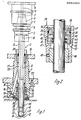
- Figure 1 shows a Boza 1 of a deep drilling machine with inserted tool 2.
- the tool 2 is fixed in a tool holder 3; the tool holder 3 has a plug-in cone 4, with which the unit formed by the tool 2 and the tool holder 3 can be inserted into the receiving part 5 of a tool spindle 6, which has a circumferential groove 7 for locking, into which (not shown) claws in the receiving part 5 intervention.
- the unit formed by tool 2 and tool holder 3 can be replaced when a gripper (not shown) engages in groove 8 and pulls tool holder 3 (with tool 2) out of receiving part 3 after unlocking. Then the same gripper can be inserted from a magazine Remove another tool and insert it in the receiving part.
- Tool 2 is a deep drilling tool.
- the tool tip is constantly cooled by the supply of drilling oil; when the cooling lubricant is removed, the chips are removed at the same time.
- the drilling oil is guided as follows: the drilling oil is fed to the Boza 1 via the connection 16 and line 18. It enters from the interior 23 of the housing 21 of the Boza 1 into the free space 17 between the pipe section 14 and the bore 20. The chips are discharged through the channel 9, which opens into the end face 12 of the drill head 13, and the adjoining channels 10, 11.
- the housing 21 of the Boza 1 is fastened to a carrier plate 22 which is connected to the machine frame (not shown).
- the interior 23 is closed towards the tool spindle 6 (at the top in FIG. 1) by a stuffing box 24 (see FIG. 2 for details), which defines the outer circumference (in the direction of drilling) of the rear pipe section 15 seals.
- the sealing takes place in that the drill bush holder 26 arranged in a recess 25 with the sealing ring 30 and the drill bush 27 is pressed by a spring 28 against the end face 29 of the bore 20.
- the special feature of the tool 2 is that it is designed in two stages, ie it consists of a front pipe section 14 and a rear pipe section 15.
- the outer diameter of both pipe sections is different.
- the diameter of the rear pipe section 15 in the drilling direction is larger than that of the drilling head 13 or the cutting edge 33 and the contact strips 31, 32. It is accordingly also larger than that of the front pipe section 14 in the drilling direction.
- the outer diameter of the guide strips 31, 32 is still the same as the inner diameter of the drill bushing 27.
- the drill head 13 can namely be moved out of the Boza 1 through the stuffing box 24. This happens when the tool spindle 6 with the receiving part 5 and the tool 2 moves upward to change the tool.
- This two-stage design ensures that the stuffing box 24 forms a seal with respect to the rear pipe section 15 during operation, and that on the other hand the drill head 13, which has a smaller diameter than the rear pipe section 15, is moved through the stuffing box 24 when the tool is changed can.
- This is only possible if the drill head 13 is located on a pipe section 14, which in turn has a smaller diameter than the drill head 13.
- This configuration therefore ensures for the first time that the entire tool can be removed from the Boza without dismantling for tool change. A simple tool change in the receiving part 5 of the tool spindle 6 is thus also possible.
- Figure 2 shows the stuffing box 24. It consists of a sleeve 34 with an external thread 35 which is screwed into the housing 21.
- a slide ring 39 is held by Seeger ring 36 and spacer sleeve 37 and sealed by means of sealing ring 38.
- the sliding shoulder 40 of a sealing ring 41 bears against it in the axial direction, in which two grooves 42 and 43 are provided, in which O-rings 44 and 45 are arranged.
- the grooves 42 and 43 are connected radially on the outside to a drilling oil supply bore 46 which opens downwards into the free cylindrical interior 47 of the sleeve 34.
- a bearing shell 48 is also arranged in the sleeve 34 and is held in position by a threaded pin 49.
- pressurized drilling oil penetrates from the space 23 into the interior 47 and into the drilling oil supply bore 46.
- the pressurized drilling oil also acts in the grooves 42 and 43 from the outside on the 0-rings 44 and 45 and presses it inwards onto the surface of the rear pipe section 15.
- the two tube sections 14, 15 e.g. can be formed in that they are made from one part with correspondingly stepped outer dimensions.
- a screw connection has the advantage that the front pipe sections can be replaced with drill heads for different diameters on a rear pipe section. It is also possible to provide a collet at the end of the rear pipe section in which the front pipe section, which is smaller in diameter, is received. The outer circumference of the collet must not be larger than the outer circumference of the rear pipe section.
Landscapes
- Engineering & Computer Science (AREA)
- Mechanical Engineering (AREA)
- General Engineering & Computer Science (AREA)
- Physics & Mathematics (AREA)
- Architecture (AREA)
- Fluid Mechanics (AREA)
- Drilling And Boring (AREA)
- Earth Drilling (AREA)
- Drilling Tools (AREA)
Applications Claiming Priority (2)
| Application Number | Priority Date | Filing Date | Title |
|---|---|---|---|
| DE3203134 | 1982-01-30 | ||
| DE3203134A DE3203134C2 (de) | 1982-01-30 | 1982-01-30 | Tiefbohrwerkzeug |
Publications (2)
| Publication Number | Publication Date |
|---|---|
| EP0085354A2 true EP0085354A2 (fr) | 1983-08-10 |
| EP0085354A3 EP0085354A3 (fr) | 1984-11-28 |
Family
ID=6154381
Family Applications (1)
| Application Number | Title | Priority Date | Filing Date |
|---|---|---|---|
| EP83100425A Withdrawn EP0085354A3 (fr) | 1982-01-30 | 1983-01-19 | Outil d'alésage de trous profonds |
Country Status (3)
| Country | Link |
|---|---|
| US (1) | US4591300A (fr) |
| EP (1) | EP0085354A3 (fr) |
| DE (1) | DE3203134C2 (fr) |
Cited By (5)
| Publication number | Priority date | Publication date | Assignee | Title |
|---|---|---|---|---|
| US4475853A (en) * | 1982-12-30 | 1984-10-09 | Deere & Company | Rotary tool and guide |
| EP0202211A3 (en) * | 1985-05-17 | 1988-08-10 | Santrade Ltd. | Drill |
| EP0097879B1 (fr) * | 1982-06-29 | 1990-10-17 | Gelsen, Karl-Heinz | Appareil de forage |
| EP0517280A3 (en) * | 1991-06-07 | 1993-10-06 | Sihi Gmbh & Co Kg | Shaft passage |
| WO1996031307A1 (fr) * | 1995-04-07 | 1996-10-10 | Komet Präzisionswerkzeuge Robert Breuning Gmbh | Dispositif d'usinage par enlevement de copeaux |
Families Citing this family (10)
| Publication number | Priority date | Publication date | Assignee | Title |
|---|---|---|---|---|
| DE69007241T2 (de) * | 1989-11-25 | 1994-06-23 | Omi Kogyo Kk | Hohlbohrer. |
| US5544985A (en) * | 1994-09-15 | 1996-08-13 | Autodie International | Deep bore drilling apparatus with rotatable single tube system |
| US20030002933A1 (en) * | 1997-06-12 | 2003-01-02 | Gerhard Schanz | Rotary shaft tool and process for machining bores with such a shaft tool |
| DE20006247U1 (de) | 2000-04-05 | 2000-08-17 | Joist, Alexander, Dr., 49808 Lingen | Kernbohrer, insbesondere Markraumbohrer für Röhrenknochen |
| US7207751B2 (en) * | 2004-02-02 | 2007-04-24 | Rfour, Inc. | Gun drill guide and gun drill guide assembly |
| US7160067B2 (en) * | 2004-07-13 | 2007-01-09 | Ford Motor Company | Tool holder assembly |
| US20060029479A1 (en) * | 2004-08-03 | 2006-02-09 | Ford Motor Company | Tool holder assembly |
| US7090448B2 (en) * | 2004-08-03 | 2006-08-15 | Ford Motor Company | Tool holder assembly |
| DE102010018959A1 (de) * | 2010-04-23 | 2011-10-27 | Tbt Tiefbohrtechnik Gmbh + Co | Bohrkopf für ein Tiefbohrwerkzeug zum BTA-Tiefbohren und Tiefbohrwerkzeug |
| JP7341824B2 (ja) * | 2019-09-27 | 2023-09-11 | 川崎重工業株式会社 | 複動式摩擦攪拌点接合装置及び複動式摩擦攪拌点接合装置の運転方法 |
Family Cites Families (20)
| Publication number | Priority date | Publication date | Assignee | Title |
|---|---|---|---|---|
| US2741936A (en) * | 1951-03-10 | 1956-04-17 | Wohlfahrt Fred | Method of forming holes in metal |
| FR1063883A (fr) * | 1952-06-12 | 1954-05-07 | Perfectionnements au forage et à l'alésage | |
| US2977827A (en) * | 1953-04-27 | 1961-04-04 | Foster Wheeler Corp | Cutting apparatus |
| US2708852A (en) * | 1953-11-16 | 1955-05-24 | Wohlfahrt Fred | Oil conduit drill |
| US3317216A (en) * | 1963-11-06 | 1967-05-02 | John G Muthler | Gun drill seals |
| GB1084269A (fr) * | 1963-12-14 | 1900-01-01 | ||
| US3320833A (en) * | 1964-11-23 | 1967-05-23 | Detroit Reamer & Tool Company | Deep-hole drill and reamer |
| DE1552407A1 (de) * | 1966-12-29 | 1970-04-23 | Peter Nagel | Verfahren zum Spuelen beim Aufbohren langer Werkstueckbohrungen |
| DE1285266B (de) | 1967-05-16 | 1968-12-12 | Danfoss As Fa | Axial nicht verschieblich gelagerter Gegenlaufring bei Gleitringdichtungen |
| US3583383A (en) * | 1968-05-01 | 1971-06-08 | Wheel Trueing Tool Co | Drilling device with coolant supply |
| GB1269571A (en) * | 1969-02-05 | 1972-04-06 | Crane Packing Ltd | Seal assemblies |
| US3599991A (en) | 1969-10-31 | 1971-08-17 | Grove Valve & Regulator Co | Auxiliary valve stem seal |
| US3701607A (en) * | 1970-10-23 | 1972-10-31 | Robert C Johnson | Deep hole drilling tool |
| SE356112B (fr) | 1971-11-09 | 1973-05-14 | Forsheda Ideutveckling Ab | |
| US3767315A (en) * | 1971-12-30 | 1973-10-23 | D Burks | Fluid assisted drill construction |
| DE2409229A1 (de) * | 1974-02-27 | 1975-09-04 | Tiefbohr Technik Gmbh | Tiefbohrmaschine mit einem motorisch verschiebbaren bohrschlitten und einem verschiebbaren bohrbuchsentraeger |
| DE2461750A1 (de) * | 1974-12-28 | 1976-07-08 | Beck August Fa | Spiralbohrer |
| SE417632B (sv) * | 1977-05-02 | 1981-03-30 | Sunds Defibrator | Tetningsanordning for axlar |
| DE2949556A1 (de) * | 1979-12-10 | 1981-06-11 | Dieter 2110 Buchholz Beck | Anordnung zum bohren mit einem hohlen bohrer |
| US4290611A (en) * | 1980-03-31 | 1981-09-22 | Crane Packing Co. | High pressure upstream pumping seal combination |
-
1982
- 1982-01-30 DE DE3203134A patent/DE3203134C2/de not_active Expired
-
1983
- 1983-01-19 EP EP83100425A patent/EP0085354A3/fr not_active Withdrawn
- 1983-01-25 US US06/460,951 patent/US4591300A/en not_active Expired - Fee Related
Cited By (6)
| Publication number | Priority date | Publication date | Assignee | Title |
|---|---|---|---|---|
| EP0097879B1 (fr) * | 1982-06-29 | 1990-10-17 | Gelsen, Karl-Heinz | Appareil de forage |
| US4475853A (en) * | 1982-12-30 | 1984-10-09 | Deere & Company | Rotary tool and guide |
| EP0202211A3 (en) * | 1985-05-17 | 1988-08-10 | Santrade Ltd. | Drill |
| EP0517280A3 (en) * | 1991-06-07 | 1993-10-06 | Sihi Gmbh & Co Kg | Shaft passage |
| WO1996031307A1 (fr) * | 1995-04-07 | 1996-10-10 | Komet Präzisionswerkzeuge Robert Breuning Gmbh | Dispositif d'usinage par enlevement de copeaux |
| US5971988A (en) * | 1995-04-07 | 1999-10-26 | Komet Praezisionswerkzeuge Robert Breuning Gmbh | Device for chip removing machining |
Also Published As
| Publication number | Publication date |
|---|---|
| DE3203134C2 (de) | 1984-01-05 |
| DE3203134A1 (de) | 1983-09-15 |
| US4591300A (en) | 1986-05-27 |
| EP0085354A3 (fr) | 1984-11-28 |
Similar Documents
| Publication | Publication Date | Title |
|---|---|---|
| DE4009940C2 (de) | Einrichtung zur spanabhebenden Bearbeitung von Werkstücken | |
| EP0085354A2 (fr) | Outil d'alésage de trous profonds | |
| DE1477578B2 (de) | Numerisch gesteuerte werkzeugmaschine | |
| DE4127433A1 (de) | Werkzeughalterung | |
| DE3109543C2 (de) | Vorrichtung zur Kühlmittelzufuhr zu mit Kühlmittelkanälen versehenen, rotierenden Schneidwerkzeugen für die spanende Metallbearbeitung, insbesondere Bohrwerkzeugen | |
| DE1812669A1 (de) | Kernbohrer | |
| DE2346729B2 (de) | Kombiniertes Schäl- und Glattwalzwerkzeug | |
| EP0229909B1 (fr) | Equipement de forage à grande profondeur | |
| DE2533803B2 (de) | Kraftbetätigtes Keilspannfutter | |
| DE3204789A1 (de) | Werkzeugwechsler | |
| DE68902953T2 (de) | Bohrmaschine, insbesondere fuer programmierbare maschine. | |
| EP0027282B1 (fr) | Rallonge de broche pour machine-outils | |
| DE69512393T2 (de) | Vorrichtung zum kühlen eines maschinenwerkzeuges in einer revolverplatte | |
| DE2820165B2 (de) | Bohrmaschine | |
| DE69619652T2 (de) | Werkzeughaltevorrichtung | |
| DE19543734C1 (de) | Werkzeughaltevorrichtung für den automatischen Werkzeugwechsel | |
| DE10241826B3 (de) | Spannfutter und Schmiereinsatz dafür | |
| DE2234825A1 (de) | Verfahren und werkzeug zur herstellung von bohrungen | |
| DE102004008166A1 (de) | Werkzeug zur spanenden Bearbeitung von Präzisionsbohrungen | |
| EP0123787B1 (fr) | Outil pour aléser des trous profonds | |
| EP1356883A1 (fr) | Dispositif de carottage | |
| DE2647633A1 (de) | Werkzeughalter | |
| DE3341252A1 (de) | Automatische werkzeugwechseleinrichtung | |
| DE3512890A1 (de) | Einrichtung zum einspannen von tiefbohrwerkzeugen fuer den automatischen werkzeugwechsel | |
| DE3249245C2 (de) | Vorrichtung zur Abdichtung eines Rohrabschnittes eines Tiefbohrwerkzeuges |
Legal Events
| Date | Code | Title | Description |
|---|---|---|---|
| PUAI | Public reference made under article 153(3) epc to a published international application that has entered the european phase |
Free format text: ORIGINAL CODE: 0009012 |
|
| AK | Designated contracting states |
Designated state(s): AT BE CH DE FR GB IT LI LU NL SE |
|
| PUAL | Search report despatched |
Free format text: ORIGINAL CODE: 0009013 |
|
| AK | Designated contracting states |
Designated state(s): AT BE CH DE FR GB IT LI LU NL SE |
|
| 17P | Request for examination filed |
Effective date: 19850223 |
|
| 17Q | First examination report despatched |
Effective date: 19860306 |
|
| RAP1 | Party data changed (applicant data changed or rights of an application transferred) |
Owner name: TBT TIEFBOHRTECHNIK GMBH UND CO. KG. |
|
| STAA | Information on the status of an ep patent application or granted ep patent |
Free format text: STATUS: THE APPLICATION HAS BEEN WITHDRAWN |
|
| 18W | Application withdrawn |
Withdrawal date: 19880921 |
|
| RIN1 | Information on inventor provided before grant (corrected) |
Inventor name: WEIBLEN, RICHARD Inventor name: JENNY, WERNER |