EP0085374A1 - Dispositif d'ancrage, notamment des soupapes d'air d'amenée et d'air d'évacuation dans des conduits de ventilation - Google Patents
Dispositif d'ancrage, notamment des soupapes d'air d'amenée et d'air d'évacuation dans des conduits de ventilation Download PDFInfo
- Publication number
- EP0085374A1 EP0085374A1 EP83100578A EP83100578A EP0085374A1 EP 0085374 A1 EP0085374 A1 EP 0085374A1 EP 83100578 A EP83100578 A EP 83100578A EP 83100578 A EP83100578 A EP 83100578A EP 0085374 A1 EP0085374 A1 EP 0085374A1
- Authority
- EP
- European Patent Office
- Prior art keywords
- locking device
- opening
- valve
- tongue
- tongues
- Prior art date
- Legal status (The legal status is an assumption and is not a legal conclusion. Google has not performed a legal analysis and makes no representation as to the accuracy of the status listed.)
- Granted
Links
- 238000004873 anchoring Methods 0.000 title claims abstract description 42
- 238000009423 ventilation Methods 0.000 title claims abstract description 11
- 210000002105 tongue Anatomy 0.000 claims abstract description 72
- 230000002093 peripheral effect Effects 0.000 abstract description 4
- 238000005452 bending Methods 0.000 description 5
- 239000000463 material Substances 0.000 description 4
- 238000003780 insertion Methods 0.000 description 3
- 230000037431 insertion Effects 0.000 description 3
- 230000035515 penetration Effects 0.000 description 3
- 238000004080 punching Methods 0.000 description 3
- 230000000694 effects Effects 0.000 description 2
- 210000000056 organ Anatomy 0.000 description 2
- 229910000639 Spring steel Inorganic materials 0.000 description 1
- 238000004026 adhesive bonding Methods 0.000 description 1
- 230000015572 biosynthetic process Effects 0.000 description 1
- 230000005489 elastic deformation Effects 0.000 description 1
- 238000005516 engineering process Methods 0.000 description 1
- 238000001746 injection moulding Methods 0.000 description 1
- 238000009434 installation Methods 0.000 description 1
- 238000000034 method Methods 0.000 description 1
- 230000000149 penetrating effect Effects 0.000 description 1
- 210000005182 tip of the tongue Anatomy 0.000 description 1
- 230000007704 transition Effects 0.000 description 1
- 238000003466 welding Methods 0.000 description 1
Images


Classifications
-
- F—MECHANICAL ENGINEERING; LIGHTING; HEATING; WEAPONS; BLASTING
- F16—ENGINEERING ELEMENTS AND UNITS; GENERAL MEASURES FOR PRODUCING AND MAINTAINING EFFECTIVE FUNCTIONING OF MACHINES OR INSTALLATIONS; THERMAL INSULATION IN GENERAL
- F16B—DEVICES FOR FASTENING OR SECURING CONSTRUCTIONAL ELEMENTS OR MACHINE PARTS TOGETHER, e.g. NAILS, BOLTS, CIRCLIPS, CLAMPS, CLIPS OR WEDGES; JOINTS OR JOINTING
- F16B2/00—Friction-grip releasable fastenings
- F16B2/20—Clips, i.e. with gripping action effected solely by the inherent resistance to deformation of the material of the fastening
- F16B2/22—Clips, i.e. with gripping action effected solely by the inherent resistance to deformation of the material of the fastening of resilient material, e.g. rubbery material
- F16B2/24—Clips, i.e. with gripping action effected solely by the inherent resistance to deformation of the material of the fastening of resilient material, e.g. rubbery material of metal
- F16B2/241—Clips, i.e. with gripping action effected solely by the inherent resistance to deformation of the material of the fastening of resilient material, e.g. rubbery material of metal of sheet metal
-
- F—MECHANICAL ENGINEERING; LIGHTING; HEATING; WEAPONS; BLASTING
- F24—HEATING; RANGES; VENTILATING
- F24F—AIR-CONDITIONING; AIR-HUMIDIFICATION; VENTILATION; USE OF AIR CURRENTS FOR SCREENING
- F24F13/00—Details common to, or for air-conditioning, air-humidification, ventilation or use of air currents for screening
-
- Y—GENERAL TAGGING OF NEW TECHNOLOGICAL DEVELOPMENTS; GENERAL TAGGING OF CROSS-SECTIONAL TECHNOLOGIES SPANNING OVER SEVERAL SECTIONS OF THE IPC; TECHNICAL SUBJECTS COVERED BY FORMER USPC CROSS-REFERENCE ART COLLECTIONS [XRACs] AND DIGESTS
- Y10—TECHNICAL SUBJECTS COVERED BY FORMER USPC
- Y10T—TECHNICAL SUBJECTS COVERED BY FORMER US CLASSIFICATION
- Y10T403/00—Joints and connections
- Y10T403/70—Interfitted members
- Y10T403/7047—Radially interposed shim or bushing
- Y10T403/7051—Wedging or camming
- Y10T403/7052—Engaged by axial movement
- Y10T403/7058—Split or slotted bushing
-
- Y—GENERAL TAGGING OF NEW TECHNOLOGICAL DEVELOPMENTS; GENERAL TAGGING OF CROSS-SECTIONAL TECHNOLOGIES SPANNING OVER SEVERAL SECTIONS OF THE IPC; TECHNICAL SUBJECTS COVERED BY FORMER USPC CROSS-REFERENCE ART COLLECTIONS [XRACs] AND DIGESTS
- Y10—TECHNICAL SUBJECTS COVERED BY FORMER USPC
- Y10T—TECHNICAL SUBJECTS COVERED BY FORMER US CLASSIFICATION
- Y10T403/00—Joints and connections
- Y10T403/70—Interfitted members
- Y10T403/7075—Interfitted members including discrete retainer
- Y10T403/7077—Interfitted members including discrete retainer for telescoping members
Definitions
- Locking device in particular for anchoring supply and exhaust air valves in ventilation ducts
- the invention relates to a locking device according to the preamble of claim 1.
- supply and exhaust air valves are often to be installed in openings of ventilation ducts of different widths or diameters and even of different designs.
- their openings can often be rough and uneven, e.g. in the form of normal masonry openings, or there may be changing irregularities.
- a cylindrical or conical extension of a valve or the like is provided with approximately tangentially arranged, resilient leaves, which only act in the axial direction in the first script. Also know the free ends of the leaves would rest on the opening wall, so penetration into recesses or other unevenness would hardly be possible, since the valve extension or the like penetrating into the opening mentioned should of course fill the opening without too much play, which means that the Leaves are bent to the almost completely flat peripheral contact on the aforementioned valve extension or the like, so that only the flat outer sides of the leaf come into effect, so that effective locking is not possible in most cases.
- the invention has for its object to provide a new locking device that is simple and reliable, can be manufactured and attached quickly, easily and inexpensively, and in particular an attachment of the valve or the like. without e.g. cylindrical spigot projecting into the ventilation duct openings.
- the existing state of this technology should generally be further developed.
- the invention has the advantages over the known that a supply or exhaust air valve or the like. can be fastened directly in an opening of a channel with a flat or even very irregularly uneven inner wall even without an insertion nozzle or the like.
- the division of the blade of an anchoring element according to the invention into several tongues has the advantage that each tongue can act individually and can adapt to the anchoring area in the best possible way, the known extension of the tongues tending towards tangential purpose allows moderate elastic bending of each tongue in the radial direction and furthermore the at least approximately pointed design and angling outwards of the free tongue ends to essentially radial means enables easy and effective penetration even into smaller and irregularly arranged recesses in the opening wall or in the absence of such recesses a punctiform friction lock by said tongue tips in, for example, a cylindrical stub or the like.
- Fig. 1 is therefore a complete locking device 1 according to the invention with a valve 2 or the like partially shown in the drawing.
- a valve 2 or the like which, of course, can be any organ or element that needs to be anchored, and which in the case shown comprises a flange 3 with an outer, bent-back collar 4 and an inwardly directed, ring-shaped seat 5, which is e.g. is convex.
- a valve, valve part or the like. can be on a wall 6 or similar or in an opening 7 e.g. a ventilation duct for fresh or exhaust air.
- the reference numerals 6 and 7 can also designate the flange and the use of a pipe socket or the like.
- valve 2 or the like. with, for example, two anchoring elements 8 made of, for example, spring steel and / or plastic, which in the case shown are fastened by means of a base 9 on the back of the seat 5 are, for example by welding, gluing, riveting or in some other way.
- the base 9 can be made approximately rectangular and flat or at any angle or concave / convex with a view to good, for example contour-following, support on the base.
- a middle piece 10 which is triangular in the case shown, one side of the triangle adjoining and passing into the base, while the other, preferably the hypotenuse, adjoins and passes into a sheet 11 described below, while the remaining triangle side is free and in this case points towards the opening of the seat.
- the middle piece and the base preferably close an angle greater than 90 °, e.g. about 120 °, a. Of course this angle can also be smaller than 90 ° e.g. down to 60 ° and it grows under load.
- the sheet 11 (FIG. 1) is preferably approximately rectangular and is divided into tongues 12 by slits from the free ends, namely by the formation of slits 13, which do not extend to the middle piece 10. In this way, stresses on the individual tongues are transferred to a larger attachment area of the sheet and therefore not primarily to the more sensitive, for example, bent transition area between the sheet and the middle part.
- the free ends of the blade 11 or the tongues 12 are preferably designed as tongue tips 14, which are also best bent outwards, e.g. with an angle of 30 ° to 60 ° to the plane of the sheet in the direction away from the seat 5. Even the sheet 11 and the middle piece 10 preferably form an angle with one another, preferably greater than 90 °, e.g. about 120 °.
- the outer triangle side of the center piece i.e. the starting line for the leaf, in the exemplary embodiment, is in any case parallel to the valve axis or preferably slightly inclined towards it towards the free, outer triangle tip, and consequently the entire leaf is parallel or somewhat inclined towards the valve axis away from the seat, one of which line running through the tips of the tongues preferably runs approximately parallel to said side or line, which means that such a locking device can easily be inserted into an opening 7 (FIGS. 2-5).
- several anchoring members are attached, which are best aligned with the same holding direction in the circumferential direction, so that one can easily push and screw or turn the locking device.
- the tongue tips 14 are further from the central axis of the valve than the lugs of the leaves, e.g. 5 to 10 mm further, so that the anchoring member with the less elastic leaf attachments can be pressed into the opening 7, preferably without significant elastic deformation of the center piece in relation to the base, while the tongues and in particular their tips are elastic towards the central axis of the Valve are pressed, as shown in Fig. 3-5. Thanks to the slit sheet and the pointed ends, the individual tongues 12 easily engage individually with at least approximately radially oriented tips in the deepest bumps in the opening 7, so that a good and secure anchoring of the entire arrangement is automatically guaranteed.
- the plane of the blade lies in an intermediate position between the radial and tangential extension, with loads bending the blade more strongly in the direction of a tangential position.
- FIGS. 3 and 4 and 5 show different types of unevenness, grooves or the like in the opening or the pipe socket 7 of a ventilation duct. It can clearly be seen from this how the individual tongues 12 can engage individually in the different depths of the uneven wall of the ventilation duct.
- An anchoring element according to the invention can easily be produced by simple punching and / or bending processes or by injection molding, and the attachment also poses no further problem.
- the design of the anchoring elements can be varied depending on requirements and individual wishes, as can be seen from FIGS. 6 to 17. This allows you to select and control the various properties, e.g. the elasticity, the insertion properties, the anchoring area, which is desirable or necessary for installation in a ventilation duct or any opening, different depth and varying point locking in connection with the selection of a suitable number of tongue tips etc.
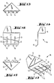
- FIG. 6 While each of the anchoring members 8 shown in FIG. 1 uses three tongues 12 of approximately the same width, another embodiment of an anchoring member 15 (FIG. 6) has a sheet 35 with four tongues which are mutually separated by the slots 13. Because of its four contact points, this anchoring member 15 can offer an even better hold than that shown in FIG. 1. In particular, the outer edge of the outer tongue remote from the base can run obliquely, so that the tongue attachment in question first penetrates into the opening 7, which facilitates insertion.
- FIG. 7 another Verartkanssorgan 16 can be seen, whose blade 18 is provided with two wider tongues 19 and a narrower tongue 20, each of the wider tongues 19 having two tongue tips 17 and the narrower tongue 20 being provided with a single tongue tip 14.
- FIG. 8 Another embodiment of an anchoring member 21 is shown in FIG. 8.
- the anchoring member 21 is provided with five e.g. Equally wide tongues of a blade 36, which are separated from one another by slots and at their free ends asymmetrical, e.g. have tongue tips 22 bevelled on one side. This can be advantageous in individual cases because the punching tool for punching out the anchoring member 21 can be simple.
- FIG. 9 shows a further exemplary embodiment of an anchoring member 23, the tongues of its leaf 37 being separated from one another by slots, approximately the same width and having dovetail-shaped tongue tips 24.
- each tongue rests on two support points, similar to the exemplary embodiment according to FIG. 7, where two tongues have similar properties.
- the holding force of the anchoring member 23 is advantageously improved.
- two relatively wide, but e.g. tongues 26, 27 of different widths and a relatively narrow tongue 12 are provided.
- the tongues are separated from one another by slots.
- the tongue tips 28, 29, 30 provided on all tongues are of multi-point design and thereby secure each tongue 12, 26, 27 a multiple support on the wall of the opening in which the locking device is to be anchored. Because of their width, the two relatively wide tongues 26, 27 are equipped with relatively rigid material properties and therefore also lead to increased holding forces compared to the narrow tongues described above.
- FIG. 11 shows another embodiment of an anchoring member 31, the sheet 39 of which is provided with two relatively wide tongues 32, 33, which at their free ends are e.g. each have two asymmetrical tongue tips 34.
- the relatively wide tongues 32, 33 ensure great rigidity of the material, the tongue tips 34 create a multiple, point-like support on the wall material in the opening in which the locking device is to be attached.
- the outer edge of the inner tongue runs obliquely, so that the anchoring further in the opening only begins at the same time as the parts 2-5 are given more space.
- FIG. 12 shows a side view of the anchoring members 11, 15, 16, 21, 23, 25, 31. This also shows a tongue tip course that is angled with respect to the flat course of the tongues in question. Accordingly, all tongue tips of the described exemplary embodiments are preferably angled.
Landscapes
- Engineering & Computer Science (AREA)
- General Engineering & Computer Science (AREA)
- Mechanical Engineering (AREA)
- Chemical & Material Sciences (AREA)
- Combustion & Propulsion (AREA)
- Valve Housings (AREA)
- Earth Drilling (AREA)
- Compressor (AREA)
- Separation By Low-Temperature Treatments (AREA)
- Self-Closing Valves And Venting Or Aerating Valves (AREA)
- Flanged Joints, Insulating Joints, And Other Joints (AREA)
- Valves And Accessory Devices For Braking Systems (AREA)
- Building Environments (AREA)
- Catching Or Destruction (AREA)
- Percussion Or Vibration Massage (AREA)
- Drying Of Solid Materials (AREA)
- Dowels (AREA)
- Piles And Underground Anchors (AREA)
- Treatment Of Fiber Materials (AREA)
- Respiratory Apparatuses And Protective Means (AREA)
- Duct Arrangements (AREA)
Priority Applications (1)
| Application Number | Priority Date | Filing Date | Title |
|---|---|---|---|
| AT83100578T ATE17397T1 (de) | 1982-01-29 | 1983-01-23 | Verankerungsvorrichtung, insbesondere von zuund abluftventilen in ventilationskanaelen. |
Applications Claiming Priority (2)
| Application Number | Priority Date | Filing Date | Title |
|---|---|---|---|
| SE8200488A SE8200488L (sv) | 1982-01-29 | 1982-01-29 | Arreteringsanordning, serskilt for forankring av till- och franluftventiler i ventilationskanaler |
| SE8200488 | 1982-01-29 |
Publications (2)
| Publication Number | Publication Date |
|---|---|
| EP0085374A1 true EP0085374A1 (fr) | 1983-08-10 |
| EP0085374B1 EP0085374B1 (fr) | 1986-01-08 |
Family
ID=20345860
Family Applications (1)
| Application Number | Title | Priority Date | Filing Date |
|---|---|---|---|
| EP83100578A Expired EP0085374B1 (fr) | 1982-01-29 | 1983-01-23 | Dispositif d'ancrage, notamment des soupapes d'air d'amenée et d'air d'évacuation dans des conduits de ventilation |
Country Status (9)
| Country | Link |
|---|---|
| US (1) | US4482267A (fr) |
| EP (1) | EP0085374B1 (fr) |
| AT (1) | ATE17397T1 (fr) |
| CA (1) | CA1202512A (fr) |
| DE (1) | DE3361736D1 (fr) |
| DK (1) | DK153656C (fr) |
| FI (1) | FI72197C (fr) |
| NO (1) | NO153317C (fr) |
| SE (1) | SE8200488L (fr) |
Cited By (1)
| Publication number | Priority date | Publication date | Assignee | Title |
|---|---|---|---|---|
| WO2006095363A2 (fr) | 2005-02-01 | 2006-09-14 | Troikaa Pharmaceuticals Ltd | Preparations injectables de diclofenac et sels acceptables sur le plan pharmaceutique de celui-ci |
Families Citing this family (5)
| Publication number | Priority date | Publication date | Assignee | Title |
|---|---|---|---|---|
| US4727796A (en) * | 1986-10-28 | 1988-03-01 | Derkach W George | Weather cap for upstanding exhaust pipes |
| US6161589A (en) * | 1999-07-30 | 2000-12-19 | Bolotte; Russell | Pipe hole covering and sealing trim |
| US7922033B2 (en) * | 2006-01-05 | 2011-04-12 | Pentair Filtration, Inc. | Universal lid for underground access boxes |
| US7540683B2 (en) * | 2007-06-12 | 2009-06-02 | Salas Gary W | Subterranean conduit cover |
| US9534392B2 (en) | 2014-02-24 | 2017-01-03 | Liberty Diversified International, Inc. | Telescoping pipe boot |
Citations (3)
| Publication number | Priority date | Publication date | Assignee | Title |
|---|---|---|---|---|
| GB637357A (en) * | 1948-05-21 | 1950-05-17 | John Pearson Wilcox | Improvements in closure members for apertures or receptacles |
| GB734857A (en) * | 1952-09-09 | 1955-08-10 | Carr Fastrner Company Ltd | Improvements in and relating to aperture stoppers |
| SE391384B (sv) * | 1975-06-16 | 1977-02-14 | Svenska Flaektfabriken Ab | Stos for montage av ett ventilationselement i en oppning i ett tak eller en vegg |
Family Cites Families (10)
| Publication number | Priority date | Publication date | Assignee | Title |
|---|---|---|---|---|
| US2505147A (en) * | 1947-08-12 | 1950-04-25 | Frank J Scallon | Ventilating device |
| US2660106A (en) * | 1951-08-03 | 1953-11-24 | Arthur W Gray | Chimney cowl |
| US2805616A (en) * | 1954-12-10 | 1957-09-10 | Roth Patrick | Chimney cowl |
| US2950937A (en) * | 1957-11-07 | 1960-08-30 | United Carr Fastener Corp | Fastening device |
| US2976796A (en) * | 1959-02-16 | 1961-03-28 | Albert W Anthony | Chimney cap |
| US3028184A (en) * | 1960-03-17 | 1962-04-03 | United Carr Fastener Corp | Fastened joint constructions |
| US3236171A (en) * | 1964-06-29 | 1966-02-22 | Vaskov Ind Inc | Air circulation register attachment device |
| DE7537113U (de) * | 1975-11-19 | 1976-05-13 | Ab Svenska Flaektfabriken, Nacka (Schweden) | Ventil, insbesondere lufteinlassventil fuer aufenthaltsraeume |
| FI59299C (fi) * | 1978-03-31 | 1990-07-02 | Halton Oy | Ilmanvaihtoventtiilin kiinnitys poikkileikkaukseltaan pyöreän kanavan päähän |
| US4436021A (en) * | 1982-03-12 | 1984-03-13 | Hy-C Company Inc. | Chimney cap |
-
1982
- 1982-01-29 SE SE8200488A patent/SE8200488L/ not_active Application Discontinuation
-
1983
- 1983-01-23 EP EP83100578A patent/EP0085374B1/fr not_active Expired
- 1983-01-23 AT AT83100578T patent/ATE17397T1/de not_active IP Right Cessation
- 1983-01-23 DE DE8383100578T patent/DE3361736D1/de not_active Expired
- 1983-01-25 DK DK028183A patent/DK153656C/da not_active IP Right Cessation
- 1983-01-26 NO NO830247A patent/NO153317C/no unknown
- 1983-01-26 US US06/461,152 patent/US4482267A/en not_active Expired - Fee Related
- 1983-01-28 CA CA000420537A patent/CA1202512A/fr not_active Expired
- 1983-01-28 FI FI830303A patent/FI72197C/fi not_active IP Right Cessation
Patent Citations (3)
| Publication number | Priority date | Publication date | Assignee | Title |
|---|---|---|---|---|
| GB637357A (en) * | 1948-05-21 | 1950-05-17 | John Pearson Wilcox | Improvements in closure members for apertures or receptacles |
| GB734857A (en) * | 1952-09-09 | 1955-08-10 | Carr Fastrner Company Ltd | Improvements in and relating to aperture stoppers |
| SE391384B (sv) * | 1975-06-16 | 1977-02-14 | Svenska Flaektfabriken Ab | Stos for montage av ett ventilationselement i en oppning i ett tak eller en vegg |
Cited By (1)
| Publication number | Priority date | Publication date | Assignee | Title |
|---|---|---|---|---|
| WO2006095363A2 (fr) | 2005-02-01 | 2006-09-14 | Troikaa Pharmaceuticals Ltd | Preparations injectables de diclofenac et sels acceptables sur le plan pharmaceutique de celui-ci |
Also Published As
| Publication number | Publication date |
|---|---|
| FI830303L (fi) | 1983-07-30 |
| DE3361736D1 (en) | 1986-02-20 |
| DK28183A (da) | 1983-07-30 |
| DK153656C (da) | 1988-12-12 |
| NO153317B (no) | 1985-11-11 |
| FI72197B (fi) | 1986-12-31 |
| DK153656B (da) | 1988-08-08 |
| DK28183D0 (da) | 1983-01-25 |
| FI72197C (fi) | 1987-04-13 |
| NO153317C (no) | 1986-02-19 |
| ATE17397T1 (de) | 1986-01-15 |
| EP0085374B1 (fr) | 1986-01-08 |
| SE8200488L (sv) | 1983-07-30 |
| CA1202512A (fr) | 1986-04-01 |
| NO830247L (no) | 1983-08-01 |
| FI830303A0 (fi) | 1983-01-28 |
| US4482267A (en) | 1984-11-13 |
Similar Documents
| Publication | Publication Date | Title |
|---|---|---|
| DE2718170C3 (de) | Befestigungsclip für verkleidete Abdeckplatten, insbesondere für Kraftfahrzeuge | |
| DE2634774C2 (de) | Wand- oder Deckenverkleidung aus Lamellen | |
| DE1295285B (de) | Anschlag- und Festhaltescheibe fuer ein Maschinenteil in einer Bohrung oder auf einer Welle | |
| WO2002003520A1 (fr) | Garniture de raccordement pourvue d"une bague elastique comme butee | |
| DE3232926A1 (de) | Vorrichtung zur verbindung von konstruktionsteilen oder konstruktionselementen miteinander | |
| DE3348339C2 (fr) | ||
| DE2016346C3 (de) | Schelle zum Befestigen eines langgestreckten Gegenstandes | |
| EP0085374B1 (fr) | Dispositif d'ancrage, notamment des soupapes d'air d'amenée et d'air d'évacuation dans des conduits de ventilation | |
| DE3038341A1 (de) | In eine wandoeffnung eines ersten bauteils einsetzbares und ueber eine rastnut mit diesem verrastbares aufnahmeteil | |
| DE19816784C2 (de) | Bolzenhaltevorrichtung | |
| DE2918530A1 (de) | Halterung, insbesondere zur verlegung und befestigung von rohren von fussbodenheizungen auf fussboeden | |
| DE3603876C2 (fr) | ||
| DE2749862B2 (de) | Möbel- oder Baubeschlag zum lösbaren Verbinden zweier Möbel- oder Bauteile | |
| EP0994262A2 (fr) | Dispositif de fixation | |
| EP0899504A2 (fr) | Boítier de luminaire | |
| DE3000759A1 (de) | Bolzen | |
| DE19957977B4 (de) | Vorrichtung aus Abdeckelement und Gewindebolzen | |
| EP2022928A1 (fr) | Lamelles dotées de taquets de guidage latéraux | |
| DE2946993C2 (fr) | ||
| DE69809780T2 (de) | Schneideinsatzhalter und schlüssel für schneideinsatzhalter | |
| DE3208314C2 (fr) | ||
| DE102004053989B4 (de) | Türfeststellvorrichtung | |
| EP3309416A1 (fr) | Dispositif de fixation permettant la fixation par encliquetage dans une omission ainsi que système de fixation comprenant un tel dispositif de fixation | |
| EP0753918A1 (fr) | Elément d'entrée de boîtier à relève de contrainte en traction | |
| DE102023131757A1 (de) | Spreizverbinder und Verbindung zweier Bauteile mit dem Spreizverbinder |
Legal Events
| Date | Code | Title | Description |
|---|---|---|---|
| PUAI | Public reference made under article 153(3) epc to a published international application that has entered the european phase |
Free format text: ORIGINAL CODE: 0009012 |
|
| AK | Designated contracting states |
Designated state(s): AT BE CH DE FR GB IT LI NL SE |
|
| 17P | Request for examination filed |
Effective date: 19831128 |
|
| GRAA | (expected) grant |
Free format text: ORIGINAL CODE: 0009210 |
|
| AK | Designated contracting states |
Designated state(s): AT BE CH DE FR GB IT LI NL SE |
|
| REF | Corresponds to: |
Ref document number: 17397 Country of ref document: AT Date of ref document: 19860115 Kind code of ref document: T |
|
| REF | Corresponds to: |
Ref document number: 3361736 Country of ref document: DE Date of ref document: 19860220 |
|
| ET | Fr: translation filed | ||
| ITF | It: translation for a ep patent filed | ||
| PLBE | No opposition filed within time limit |
Free format text: ORIGINAL CODE: 0009261 |
|
| STAA | Information on the status of an ep patent application or granted ep patent |
Free format text: STATUS: NO OPPOSITION FILED WITHIN TIME LIMIT |
|
| 26N | No opposition filed | ||
| PGFP | Annual fee paid to national office [announced via postgrant information from national office to epo] |
Ref country code: NL Payment date: 19890131 Year of fee payment: 8 |
|
| PGFP | Annual fee paid to national office [announced via postgrant information from national office to epo] |
Ref country code: AT Payment date: 19900112 Year of fee payment: 8 |
|
| PGFP | Annual fee paid to national office [announced via postgrant information from national office to epo] |
Ref country code: FR Payment date: 19900115 Year of fee payment: 8 |
|
| PGFP | Annual fee paid to national office [announced via postgrant information from national office to epo] |
Ref country code: CH Payment date: 19900130 Year of fee payment: 8 |
|
| ITTA | It: last paid annual fee | ||
| PGFP | Annual fee paid to national office [announced via postgrant information from national office to epo] |
Ref country code: GB Payment date: 19900131 Year of fee payment: 8 |
|
| PGFP | Annual fee paid to national office [announced via postgrant information from national office to epo] |
Ref country code: BE Payment date: 19900221 Year of fee payment: 8 |
|
| PGFP | Annual fee paid to national office [announced via postgrant information from national office to epo] |
Ref country code: DE Payment date: 19900228 Year of fee payment: 8 |
|
| PG25 | Lapsed in a contracting state [announced via postgrant information from national office to epo] |
Ref country code: GB Effective date: 19910123 Ref country code: AT Effective date: 19910123 |
|
| PG25 | Lapsed in a contracting state [announced via postgrant information from national office to epo] |
Ref country code: LI Effective date: 19910131 Ref country code: CH Effective date: 19910131 Ref country code: BE Effective date: 19910131 |
|
| PG25 | Lapsed in a contracting state [announced via postgrant information from national office to epo] |
Ref country code: NL Effective date: 19910801 |
|
| NLV4 | Nl: lapsed or anulled due to non-payment of the annual fee | ||
| GBPC | Gb: european patent ceased through non-payment of renewal fee | ||
| PG25 | Lapsed in a contracting state [announced via postgrant information from national office to epo] |
Ref country code: FR Effective date: 19910930 |
|
| REG | Reference to a national code |
Ref country code: CH Ref legal event code: PL |
|
| PG25 | Lapsed in a contracting state [announced via postgrant information from national office to epo] |
Ref country code: DE Effective date: 19911001 |
|
| REG | Reference to a national code |
Ref country code: FR Ref legal event code: ST |
|
| PGFP | Annual fee paid to national office [announced via postgrant information from national office to epo] |
Ref country code: SE Payment date: 19940117 Year of fee payment: 12 |
|
| PG25 | Lapsed in a contracting state [announced via postgrant information from national office to epo] |
Ref country code: SE Effective date: 19950124 |
|
| EAL | Se: european patent in force in sweden |
Ref document number: 83100578.0 |
|
| EUG | Se: european patent has lapsed |
Ref document number: 83100578.0 |