EP0085375A1 - Soupape, notamment soupape d'échappement d'air - Google Patents
Soupape, notamment soupape d'échappement d'air Download PDFInfo
- Publication number
- EP0085375A1 EP0085375A1 EP19830100579 EP83100579A EP0085375A1 EP 0085375 A1 EP0085375 A1 EP 0085375A1 EP 19830100579 EP19830100579 EP 19830100579 EP 83100579 A EP83100579 A EP 83100579A EP 0085375 A1 EP0085375 A1 EP 0085375A1
- Authority
- EP
- European Patent Office
- Prior art keywords
- valve
- valve body
- valve seat
- seat surface
- spring
- Prior art date
- Legal status (The legal status is an assumption and is not a legal conclusion. Google has not performed a legal analysis and makes no representation as to the accuracy of the status listed.)
- Granted
Links
Images


Classifications
-
- F—MECHANICAL ENGINEERING; LIGHTING; HEATING; WEAPONS; BLASTING
- F24—HEATING; RANGES; VENTILATING
- F24F—AIR-CONDITIONING; AIR-HUMIDIFICATION; VENTILATION; USE OF AIR CURRENTS FOR SCREENING
- F24F13/00—Details common to, or for air-conditioning, air-humidification, ventilation or use of air currents for screening
- F24F13/08—Air-flow control members, e.g. louvres, grilles, flaps or guide plates
-
- Y—GENERAL TAGGING OF NEW TECHNOLOGICAL DEVELOPMENTS; GENERAL TAGGING OF CROSS-SECTIONAL TECHNOLOGIES SPANNING OVER SEVERAL SECTIONS OF THE IPC; TECHNICAL SUBJECTS COVERED BY FORMER USPC CROSS-REFERENCE ART COLLECTIONS [XRACs] AND DIGESTS
- Y10—TECHNICAL SUBJECTS COVERED BY FORMER USPC
- Y10T—TECHNICAL SUBJECTS COVERED BY FORMER US CLASSIFICATION
- Y10T137/00—Fluid handling
- Y10T137/1624—Destructible or deformable element controlled
- Y10T137/1797—Heat destructible or fusible
- Y10T137/1819—Safety cut-off
Definitions
- the invention relates to a valve, in particular an exhaust valve, according to the preamble of claim 1.
- the valve housing has a frustoconical seat which works together with a valve body which has a similarly shaped seat but has smaller dimensions, so that a more or less large, crescent-shaped gap is formed through which the exhaust air can pass.
- the valve body is on the seat e.g. anchored with a self-tapping screw, e.g. passed through an axial slot in the seat from the rear and tightened in the desired position of the valve body before the valve e.g. is attached in a suction channel.
- the valve body can be slidably mounted with a friction brake. Further anchoring and setting options for the valve body are known.
- a partially spherical or partially conical valve body is provided with the aid of a center axis for complete or partial contact with an analogue seat surface, whereby a flow passing through the valve is interrupted or throttled.
- a valve construction is both bulky and complicated, making it relatively expensive.
- the adjusting mechanism requires a large number of complex and interacting parts and complicated preparations are required in order to assemble or mount such a valve.
- the valve body is always arranged in the middle of the air passage or even a part of it, in which the center axis carrying the valve body and its suspension elements are very disruptive, apart from the fact that in this way additional tendencies towards contamination of the valve over time and others below specified disadvantages exist.
- valve construction with an outer cylindrical tube with openings arranged at approximately diametrical points as the inlet and outlet.
- An inner tube is inserted into this outer tube with a positive fit, which leaves openings open in a manner similar to the outer tube.
- the inner tube can be rotated by means of a handle protruding through the outer tube, so that the various openings completely or partially or not at all overlap in what way maximum or throttled or blocked flow is obtained.
- a ventilation duct with a large diameter is required to hold the valve and the through openings are nevertheless kept relatively small, since otherwise a blocking function would not be obtained.
- the handle is arranged at the most unsuitable point, namely in the middle in front of the mouth of the ventilation duct, so that in any case no significant air flow can pass there, which is instead forced upwards or downwards, which represents a reprehensible limitation.
- the construction resembles a flute and should produce its own tones with forced air flow, which is completely unacceptable with a valve.
- the construction is also very space and material consuming, carries great risks of contamination and is extremely difficult to maintain. When made of metal, the parts can easily rust together and the valve can easily be inadvertently incorrectly adjusted, which is what the handle arrangement invites.
- the valve may not be applicable for automatic closing, for example in the case of a fire valve, since such a double-cylindrical design requires a large actuating force.
- the handle is inviting both in the way and to incorrect settings, which is of course possible in principle by the fact that the handle designed as an adjusting member is not arranged to be stationary but movable, and this is also in a special opening with requirements of at least the same length in the circumferential direction like an outer tube opening, through which air should pass.
- valve constructions are therefore disadvantageous in many respects, especially since a long time has passed since their development and in the course of time the demands regarding various functions and properties of a valve have increased, which properties and functions are in any case not achieved in significant combinations with the previously known constructions .
- the very high demand for low intrinsic noise development should be mentioned here, namely in all operating situations and under all operating conditions or in certain cases with a certain installation position and under certain certain operating conditions.
- Infinitely variable adjustability is another wish, preferably between the maximum free and fully closed passage opening, the maximum opening width being able to correspond to the essential part of the cross section of a ventilation duct.
- valve body preferably with simple and safe friction and manual adjustability or with a special actuating element, e.g. a cord or an automatic fire trigger that automatically closes the valve at high temperatures.
- actuating element e.g. a cord or an automatic fire trigger that automatically closes the valve at high temperatures.
- the valve housing and / or the valve body should be easily adaptable to different applications and should not have any bulky parts.
- Such an exhaust valve should also have a long service life, be reliable in all circumstances, be easy, simple and cheap to manufacture, install and set, and special adaptation to various special purposes should be easy and simple to carry out.
- the material requirement should be low and practical.
- the appearance of the valve should be appealing because it is often fully visible, e.g. in an apartment or apartment building.
- the Invention_ is based on the object, the above. To achieve properties and functions while avoiding the aforementioned disadvantages and also to create a further improved and advantageous product.
- the object is achieved by the feature listed in the characterizing part of claim 1.
- a valve is characterized by numerous advantages, of which only a few should be mentioned at this point, while others are further described in the description.
- the maximally semi-spherical or semi-cylindrical design of the valve seat surface which is also reduced to approximately half the surface area by the through opening arranged in the middle of the surface, means that, for example, the material and space requirements are minimized, the valve seat advantageously being connected to the walls can follow a ventilation duct opening.
- the anchoring member of the valve body is in principle inaccessibly attached and the valve body can therefore easily be anchored in a certain desired operating position without the risk that the valve body position can be changed unintentionally.
- the valve body can, if desired, be brought quickly and easily into all setting positions, for example directly by easily grasping the body itself or indirectly by a regulating device or the like.
- the friction forces can always be kept within an easily determinable range.
- the valve is very easy to keep clean and there are practically no angles at which dirt can accumulate.
- an adjustment scale can be attached to the front and / or back of the valve with ease. The latter localization is preferably considered if, for example, subsequent valve adjustment by unauthorized persons should not be easy.
- valve body is provided on the valve seat surface in different positions by means of an element which is in principle stationary and bound to the valve seat No space or organs are required to be held outside the valve seat surface, in order to hold the valve body in place and in part to enable it to be adjusted.
- the valve body is arranged in all opening positions in such a way that it is not in the way of the incoming air, but in contrast facilitates its entry into the valve from all directions, to which the special eccentric position of the valve body contributes to a high degree. Nevertheless, the valve body never needs to move far from the valve seat surface, not even with the maximum opening.
- the air flowing against the valve is always directed into the valve towards the center of a subsequent ventilation duct, for example, which avoids disadvantageous, since noise-generating air angles.
- Lever ratios can also be advantageously created and exploited when attaching a regulator, so that only small actuating forces are required as a result.
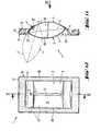
- the reference numeral 1 denotes an exhaust air valve according to the invention in its entirety, wherein, as is known, a valve mainly consists of a valve body 2 and a valve housing 8 (FIGS. 1, 2).
- the valve housing is provided with a valve seat surface 9 and a through opening 10, for example for air or another gaseous medium which is to be sucked or pressed out of or into a room.
- the valve body a sealing surface 3, which cooperates with the valve seat surface 9.
- valve body 2 consists of two spherical parts which are turned towards one another with their hollow side, so that one spherical part is equivalent to the sealing surface 3, while the opposite, spherical part an inflow surface 4 turns against the air flowing against the valve body.
- Both spherical parts can be made of metal and / or plastic material and are mutually along an edge 5 e.g. connected by gluing, welding, folding or with the help of a snap connection.
- a ventilation duct 30 has a diameter of 100 mm, at the entrance of which a valve according to the invention is to be attached.
- the sealing surface 3 has a radius of curvature of 55 mm and the inflow surface 4 has a radius of 66 mm, i.e. a radius of curvature that is about 20% larger than the sealing surface 3, which proves advantageous in all operating positions with regard to the inflowing air because it does so the inherent noise component of the valve can be kept very low.
- the through opening 10 has a diameter of 70 mm, while the valve seat surface 9 has an outside diameter on the front or free side approximately in the order of magnitude of the ventilation duct.
- the radius is for the sealing surface 3 is at least approximately the same as that for the valve seat surface 9 after both surfaces are to work together.
- an anchoring element 7 as a swivel axis or in a special case as a sliding control element for the valve body, the anchoring element of which conveniently protrudes from the sealing surface 3 as a short pin, e.g. in the form of a screw which is inserted through an opening 11 in the valve seat surface 9 and is secured against being pulled out by means of a locking washer 6 or the like.
- the anchoring member 7 is at a distance of approximately 6 mm from the through opening. Furthermore, it can be said that if the diameter of the valve body in the exemplary embodiment is approximately 88 mm, the valve body with its periphery is in the depression formed by the valve seat surface 9 when the position is completely closed.
- valve seat surface 9 merges into a flange 12 of the valve housing, which is preferably of a flat design, with a rearwardly curved, all-round edge for guiding a sealing ring 13 for sealing the valve with respect to the wall material surrounding the ventilation duct 30.
- the valve can be fastened in the channel or in various ways on the wall surrounding it, this is not described in more detail here.
- the valve body can be adjusted continuously between a completely closed position, shown with solid lines (FIG. 1), and a fully open position, indicated by dash-dotted lines, in which the flow opening is free.
- the anchoring member serving as the pivot axis and the opening 11 cooperating with it can be arranged very close to the flange 12.
- both surfaces namely the sealing surface and the inflow surface of the valve body, have minimal air resistance with regard to the inflowing air and, particularly in the vicinity of the through opening, form only a small obstacle without promoting oppositely directed flow around the valve body in the vicinity of the through opening , essentially without vortex formation, which would otherwise cause excessive self-noise development in the valve.
- the air can even flow in from any direction without any significant reduction due to the position of the valve body, which is a clear advantage.
- the strong curvature of the inflow surface of the valve body contributes to a large extent to the good flow properties in the valve body.
- the strong curvature at an early stage behind the valve body divides the incoming air, calculated from the through-opening, so that the tendency towards air flows directed transversely to the inflow direction becomes more negligible.
- a clear advantage of the valve according to the invention also lies in its attractive appearance with an elegantly shaped valve seat surface and a very elegant and stylishly designed valve body, which can be easily gripped on all sides and extremely easily into the desired one Setting position.
- the adjustability can be facilitated by any shape of a scale on the front and / or back of the valve seat surface or simply on the flange 12 or its transition line to the valve seat surface.
- the valve body can be pivoted all around without limitation, so that one can or should have an adjustment scale for each pivoting moment.
- the valve can generally be attached with any angular or clockwise position with respect to the valve body anchoring, so that even as a result of this there are substantial possibilities of determination etc.
- valve according to the invention has the decisive advantage that both valve seat surfaces, namely the sealing surface and the inflow surface of the valve body, both direct the inflowing air towards the center of the inflowing ventilation duct, as a result of which one Rotation of the air is virtually excluded.
- valve body 2 is preferably slightly inclined in the fully closed position, that is to say it is inclined backwards inwards or inwards as seen from the holder.
- the inclination may be greater, it may not be present, or the valve body may be inclined in the opposite direction, depending on which inflow properties the valve body should have when the position is fully or partially open.
- Embodiments of valve bodies and various bearings for this go from the figure. 3 and 4.
- the inflow surface 4 is significantly less curved in this case, in addition there is a greater curvature of the sealing surface 3 of the valve body (FIG. 4).
- the valve body is held in a fully closed position rotationally symmetrically on the front of the flange against which it bears perifer, the valve body in Fig. 4 being maximally sunk in an enlarged valve seat surface which can accommodate the valve body even when it is has a beginning partially open position.
- valve bodies for one and the same valve housing, e.g. with different diameters or differently shaped inflow or control surfaces.
- Only the sealing surface 3 should have at least mainly the same radius of curvature as the valve seat surface. But you can even refrain from this in a special case if you are content with a sealing closing position.
- This surface need not necessarily correspond to a spherical section, but can have any other shape, e.g. in a special case it can be in a handle indentation or elevation or the like. or even continue on a scale that, otherwise, may even be present on the sealing surface of the valve body.
- valve body can even be mounted in different ways in the valve housing.
- the valve body can be held by the influence of magnetic force by means of a magnet in the valve body and / or on the back of the housing.
- the anchoring member 7 can be guided in a slot or the like (not shown) in the valve seat surface. In this way, one has greater freedom of choice for determining in particular the two limit positions of the valve body, i.e. fully open and fully closed.
- a known pivoting and / or clamping member etc. can be used.
- the valve body does not have to have an edge as the periphery, instead it can be round, chamfered or shaped in some other way.
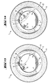
- a regulating device 14 comprises a cord 15 or the like which runs in guides 16 which are embedded in the edge of the flange of the valve housing in order to run on both sides of the anchoring element 7 through deflection elements 17, for example in the form of loops on the back of the valve seat surface, from the area of which the cord ends extend and are fastened to a holding member 18 on the back of the valve body or the sealing surface.
- the two limit positions of the valve body can be seen from the drawings.
- FIG. 7 and 8 show an embodiment of an exhaust air valve according to the invention as a fire flap, for example a spring 19 having a helical part threaded around the anchoring member 7 on the rear of the valve seat surface, the one spring end being fixed to the holding member 18 as in the previous case Valve body is fastened, and the other spring end is attached to a holding member 20 on the back of the valve seat surface.
- the valve body is normally in the open position, as indicated by dash-dotted lines, with a disk 21 or the like. made of molten metal between, for example, the anchoring member 7 and the spring 19, the latter holds the tensioned position.
- the ambient temperature then exceeds a certain limit, for example, 70 0 C, then melts the metal and the spring is released and moves the valve body quickly to the fully closed position.
- a certain limit for example, 70 0 C
- other forms for both securing and triggering the valve body are possible with such a fire damper function.
- valve 9 and 10 show a very interesting embodiment which is possible with the valve construction according to the invention.
- the valve is installed in a tube 22, the flange 12 preferably being secured by means of an inner bead 23 present in the tube.
- the flange and thus essentially the entire valve are consequently arranged diametrically in the tube, in the jacket of which a bulge or elevation 24 is provided for receiving the anchoring member 7, and then an indentation or depression 25 as a prepared location for a lever 26 or the like, which is arranged on the extended, free end of the anchoring member 7 or the pivot axis, which comes from the tube protrudes.
- FIGS. 11 and 12 also show a possible variation based on the inventive idea. This design is always important for those cases where a circular valve design is less suitable and a rectangular valve design is therefore more desirable or even possible.
- the valve seat surface 9 is not partially spherical, but partially cylindrical and laterally delimited by two inner, flat side surfaces 29.
- the valve body also has a partially cylindrical sealing surface 3 and preferably even a cylindrical inflow surface 4. These surfaces are laterally delimited by side surfaces 28, which consequently bear against the side surfaces 29 or are at least arranged opposite them.
- the sealing surface 3 of the valve body is expediently provided with a central, elongated slot 31 which can extend almost over the entire length of the sealing surface.
- the anchoring element 7, for example a screw, extends through the slot and is secured on the inside of the valve body by means of a washer 27.
- other anchoring members and anchoring devices are also conceivable.
- anchoring in the flat side surfaces may be possible.
- simple tension springs that hold the valve body only by friction.
- the side surfaces 29 of the valve housing itself can be made resilient, so that Another special spring organs are not fl BTIG.
- Such a valve body can only be moved in one direction or, in a special case, in two different directions in order to expose the through opening. Essentially, what has been said in connection with the other exemplary embodiments also applies to this valve.
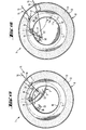
- the embodiment according to FIG. 13 is similar to that according to FIGS. 7 and 8.
- the holding member 18 can be a hole, for example, into which the e.g. approximately Z-shaped curved free end of one leg of a safety pin-like spring 19 is inserted.
- the other spring leg preferably runs approximately parallel to the former, on which the second leg is secured by a clamp or the like 32 made of molten metal in the region of the free leg ends.
- the valve body can easily assume any position and the difference to FIGS. 7 and 8 is that the spring 19 does not exert any pivoting force on the valve body, the position of which can be secured by the anchoring element 7 or in some other way.
- the clamp or the like 32 opens, the spring expands and the released spring leg strikes a stop 20 on the rear of the valve seat, which stop is preferably a locking element for the valve in a ventilation duct 30, so that the spring with the same Organ 20 as a repositioning valve body can quickly lead to the closed position if it is not already there.
- FIG. 14 also shows a similar arrangement as in FIGS. 7 and 8, but the valve body is held in the desired position against the action of, for example, a safety pin-like spring 19 by means of a safety wire or the like 33, one end of which is attached to an organ 20 on the rear the valve seat is attached,
- a clamp or the like 32 made of molten metal which is attached directly or indirectly to the valve body, for example by surrounding the anchored spring leg end. If the clamp or the like opens when exposed to heat, the valve body is moved directly into the closed position.
- Fig. 15 is similar to Fig. 14, but the wire or the like 33 is replaced by a cord or the like 15 which extends away from the valve by means of guides or the like 16, 17 and which can be anchored in a manner known per se. This allows you to adjust the days of the valve body at a distance and the valve body is released from the cord in a similar manner as in the previous example.
- Fig. 16 is again like Fig. 13, but the valve body position is adjustable by a double cord or the like 15 anchored to the free end of the free spring leg, i.e. on the leg that is not anchored to the valve body. From here, one strand extends along the rear side of the valve body and the valve seat away from the valve, while the other strand is guided around a deflection roller 34 around the anchoring element 7, from where the strand extends further, similarly to a previously mentioned example.
- the valve body position can be set at a distance, but without the double cord being anchored, the valve body being held in position by, for example, the action of friction. This friction or the like is of course so slight that the valve is securely closed when the spring 19 is triggered.
Landscapes
- Engineering & Computer Science (AREA)
- Chemical & Material Sciences (AREA)
- Combustion & Propulsion (AREA)
- Mechanical Engineering (AREA)
- General Engineering & Computer Science (AREA)
- Lift Valve (AREA)
- Exhaust Gas After Treatment (AREA)
- Valve Device For Special Equipments (AREA)
- Compressor (AREA)
- Fluid-Driven Valves (AREA)
- Control Of The Air-Fuel Ratio Of Carburetors (AREA)
- Temperature-Responsive Valves (AREA)
- Luminescent Compositions (AREA)
- Sliding Valves (AREA)
- Nitrogen And Oxygen Or Sulfur-Condensed Heterocyclic Ring Systems (AREA)
- Glass Compositions (AREA)
- Ventilation (AREA)
- Building Environments (AREA)
- Air-Flow Control Members (AREA)
Priority Applications (1)
| Application Number | Priority Date | Filing Date | Title |
|---|---|---|---|
| AT83100579T ATE17398T1 (de) | 1982-01-29 | 1983-01-23 | Ventil, insbesondere abluftventil. |
Applications Claiming Priority (2)
| Application Number | Priority Date | Filing Date | Title |
|---|---|---|---|
| SE8200487 | 1982-01-29 | ||
| SE8200487A SE8200487L (sv) | 1982-01-29 | 1982-01-29 | Franluftventil |
Publications (2)
| Publication Number | Publication Date |
|---|---|
| EP0085375A1 true EP0085375A1 (fr) | 1983-08-10 |
| EP0085375B1 EP0085375B1 (fr) | 1986-01-08 |
Family
ID=20345859
Family Applications (1)
| Application Number | Title | Priority Date | Filing Date |
|---|---|---|---|
| EP19830100579 Expired EP0085375B1 (fr) | 1982-01-29 | 1983-01-23 | Soupape, notamment soupape d'échappement d'air |
Country Status (12)
| Country | Link |
|---|---|
| US (1) | US4512356A (fr) |
| EP (1) | EP0085375B1 (fr) |
| JP (1) | JPS58136932A (fr) |
| AT (1) | ATE17398T1 (fr) |
| AU (1) | AU550692B2 (fr) |
| CA (1) | CA1191420A (fr) |
| DE (1) | DE3361737D1 (fr) |
| DK (1) | DK159836C (fr) |
| FI (1) | FI72199C (fr) |
| IT (1) | IT8260433U1 (fr) |
| NO (1) | NO154568C (fr) |
| SE (1) | SE8200487L (fr) |
Cited By (1)
| Publication number | Priority date | Publication date | Assignee | Title |
|---|---|---|---|---|
| EP3524899A1 (fr) * | 2018-02-08 | 2019-08-14 | Vallox Oy | Dispositif de soufflage d'air d'échappement |
Families Citing this family (7)
| Publication number | Priority date | Publication date | Assignee | Title |
|---|---|---|---|---|
| FI70144C (fi) * | 1982-11-12 | 1986-09-15 | Halton Oy | Regler-/brandspjaell foer kanaler i ventilationsanlaeggningar |
| US4800919A (en) * | 1987-06-18 | 1989-01-31 | Lothar Bachmann | Flap gate assembly |
| US4762115A (en) * | 1987-08-03 | 1988-08-09 | Peter Penner | Draft plugging device for a chimney flue |
| DE4030611A1 (de) * | 1990-09-27 | 1992-04-02 | Mannesmann Ag | Absperrorgan |
| US6676508B1 (en) * | 2003-04-22 | 2004-01-13 | Gerald Graham | Magnetically controlled flow system |
| US7125332B2 (en) * | 2003-12-23 | 2006-10-24 | Pci Industries, Inc. | Ceiling radiation damper and mounting method |
| JP6229873B2 (ja) * | 2013-07-17 | 2017-11-15 | 高砂熱学工業株式会社 | 流量制御ダンパ |
Citations (1)
| Publication number | Priority date | Publication date | Assignee | Title |
|---|---|---|---|---|
| DE2503022A1 (de) * | 1974-02-12 | 1975-08-21 | Strulik Wilhelm P | Vorrichtung mit feuerschutzverschlussklappe oder mit rauchabzugklappe |
Family Cites Families (3)
| Publication number | Priority date | Publication date | Assignee | Title |
|---|---|---|---|---|
| US2665714A (en) * | 1949-01-18 | 1954-01-12 | Dolphice H Greenwood | Valve |
| US3726308A (en) * | 1971-12-09 | 1973-04-10 | Hale Fire Pump Co | Suction check valve for pumps |
| US4241748A (en) * | 1977-05-02 | 1980-12-30 | Prefco Products, Inc. | Butterfly smoke/fire damper |
-
1982
- 1982-01-29 SE SE8200487A patent/SE8200487L/ not_active Application Discontinuation
- 1982-07-28 IT ITUD1982U60433U patent/IT8260433U1/it unknown
-
1983
- 1983-01-23 DE DE8383100579T patent/DE3361737D1/de not_active Expired
- 1983-01-23 EP EP19830100579 patent/EP0085375B1/fr not_active Expired
- 1983-01-23 AT AT83100579T patent/ATE17398T1/de active
- 1983-01-26 NO NO830246A patent/NO154568C/no unknown
- 1983-01-26 US US06/461,039 patent/US4512356A/en not_active Expired - Fee Related
- 1983-01-27 CA CA000420335A patent/CA1191420A/fr not_active Expired
- 1983-01-27 FI FI830283A patent/FI72199C/fi not_active IP Right Cessation
- 1983-01-28 DK DK33983A patent/DK159836C/da not_active IP Right Cessation
- 1983-01-28 JP JP58011621A patent/JPS58136932A/ja active Pending
- 1983-01-28 AU AU10845/83A patent/AU550692B2/en not_active Ceased
Patent Citations (1)
| Publication number | Priority date | Publication date | Assignee | Title |
|---|---|---|---|---|
| DE2503022A1 (de) * | 1974-02-12 | 1975-08-21 | Strulik Wilhelm P | Vorrichtung mit feuerschutzverschlussklappe oder mit rauchabzugklappe |
Cited By (1)
| Publication number | Priority date | Publication date | Assignee | Title |
|---|---|---|---|---|
| EP3524899A1 (fr) * | 2018-02-08 | 2019-08-14 | Vallox Oy | Dispositif de soufflage d'air d'échappement |
Also Published As
| Publication number | Publication date |
|---|---|
| IT8260433V0 (it) | 1982-07-28 |
| AU1084583A (en) | 1983-08-04 |
| EP0085375B1 (fr) | 1986-01-08 |
| SE8200487L (sv) | 1983-07-30 |
| NO154568B (no) | 1986-07-14 |
| FI830283A0 (fi) | 1983-01-27 |
| FI72199B (fi) | 1986-12-31 |
| CA1191420A (fr) | 1985-08-06 |
| US4512356A (en) | 1985-04-23 |
| DK159836B (da) | 1990-12-10 |
| FI72199C (fi) | 1987-04-13 |
| DE3361737D1 (en) | 1986-02-20 |
| AU550692B2 (en) | 1986-03-27 |
| FI830283L (fi) | 1983-07-30 |
| NO154568C (no) | 1986-10-22 |
| JPS58136932A (ja) | 1983-08-15 |
| DK33983D0 (da) | 1983-01-28 |
| ATE17398T1 (de) | 1986-01-15 |
| NO830246L (no) | 1983-08-01 |
| DK33983A (da) | 1983-07-30 |
| IT8260433U1 (it) | 1984-01-28 |
| DK159836C (da) | 1991-05-06 |
Similar Documents
| Publication | Publication Date | Title |
|---|---|---|
| DE102005010550B4 (de) | Sanitärer Wasserauslauf | |
| DE69530504T2 (de) | In-line venturi | |
| DE102006043647A1 (de) | Klappenventilanordnung mit verbesserter Strömungscharakteristik | |
| EP0504749A2 (fr) | Support de douche pour barre murale | |
| DE29914962U1 (de) | Luftauslaß, insbesondere für eine Kraftfahrzeug-Lüftung | |
| DE3118823C2 (de) | Lüftungsvorrichtung | |
| DE2446025A1 (de) | Ventilfluegel fuer ein steuerventil | |
| DE1698046B2 (de) | Durchflussmengenregler | |
| EP0085375B1 (fr) | Soupape, notamment soupape d'échappement d'air | |
| DE69727678T2 (de) | Activierungsstift | |
| DE2653161C2 (de) | Luftverteilkasten für Belüftungs- und Klimaanlagen | |
| DE19601554A1 (de) | Einrichtung für das Ansaugen von Luft sowie Verfahren zur Regelung einer Einrichtung für das Ansaugen von Luft | |
| DE102019114465A1 (de) | Luftausströmer | |
| CH654399A5 (de) | Selbsttaetiges drosselorgan fuer eine lueftungsanlage. | |
| DE102019206739A1 (de) | Luftausströmer mit einer Luftregelklappe und einer Torsionsfeder | |
| DE19711679B4 (de) | Vorrichtung und Verfahren zur Regelung einer Luftströmung | |
| EP0655587A2 (fr) | Dispositif d'apport d'air | |
| EP0002713A1 (fr) | Commande du débit d'un milieu gazéiforme dans un conduit | |
| EP2930277B1 (fr) | Unité de fonctionnement sanitaire | |
| DE19629137A1 (de) | Steuereinrichtung für ein Fluid, wie Wasser | |
| DE3410078A1 (de) | Deckenluftauslass fuer hohe raeume | |
| DE69402625T2 (de) | Automatischer Durchflussmengenregler für Lüftungs- und Klimaanlagen | |
| EP1661806A1 (fr) | Dispositif de sortie d'air pour véhicules | |
| DE102012203016A1 (de) | Sanitärarmatur | |
| DE102023133444B4 (de) | Volumenstromregler |
Legal Events
| Date | Code | Title | Description |
|---|---|---|---|
| PUAI | Public reference made under article 153(3) epc to a published international application that has entered the european phase |
Free format text: ORIGINAL CODE: 0009012 |
|
| AK | Designated contracting states |
Designated state(s): AT BE CH DE FR GB IT LI NL SE |
|
| 17P | Request for examination filed |
Effective date: 19831128 |
|
| GRAA | (expected) grant |
Free format text: ORIGINAL CODE: 0009210 |
|
| AK | Designated contracting states |
Designated state(s): AT BE CH DE FR GB IT LI NL SE |
|
| REF | Corresponds to: |
Ref document number: 17398 Country of ref document: AT Date of ref document: 19860115 Kind code of ref document: T |
|
| REF | Corresponds to: |
Ref document number: 3361737 Country of ref document: DE Date of ref document: 19860220 |
|
| ET | Fr: translation filed | ||
| ITF | It: translation for a ep patent filed | ||
| PLBE | No opposition filed within time limit |
Free format text: ORIGINAL CODE: 0009261 |
|
| STAA | Information on the status of an ep patent application or granted ep patent |
Free format text: STATUS: NO OPPOSITION FILED WITHIN TIME LIMIT |
|
| 26N | No opposition filed | ||
| PGFP | Annual fee paid to national office [announced via postgrant information from national office to epo] |
Ref country code: NL Payment date: 19890131 Year of fee payment: 8 |
|
| PGFP | Annual fee paid to national office [announced via postgrant information from national office to epo] |
Ref country code: AT Payment date: 19900112 Year of fee payment: 8 |
|
| PGFP | Annual fee paid to national office [announced via postgrant information from national office to epo] |
Ref country code: FR Payment date: 19900115 Year of fee payment: 8 |
|
| PGFP | Annual fee paid to national office [announced via postgrant information from national office to epo] |
Ref country code: CH Payment date: 19900130 Year of fee payment: 8 |
|
| ITTA | It: last paid annual fee | ||
| PGFP | Annual fee paid to national office [announced via postgrant information from national office to epo] |
Ref country code: GB Payment date: 19900131 Year of fee payment: 8 |
|
| PGFP | Annual fee paid to national office [announced via postgrant information from national office to epo] |
Ref country code: BE Payment date: 19900221 Year of fee payment: 8 |
|
| PGFP | Annual fee paid to national office [announced via postgrant information from national office to epo] |
Ref country code: DE Payment date: 19900228 Year of fee payment: 8 |
|
| PG25 | Lapsed in a contracting state [announced via postgrant information from national office to epo] |
Ref country code: GB Effective date: 19910123 Ref country code: AT Effective date: 19910123 |
|
| PG25 | Lapsed in a contracting state [announced via postgrant information from national office to epo] |
Ref country code: LI Effective date: 19910131 Ref country code: CH Effective date: 19910131 Ref country code: BE Effective date: 19910131 |
|
| PG25 | Lapsed in a contracting state [announced via postgrant information from national office to epo] |
Ref country code: NL Effective date: 19910801 |
|
| NLV4 | Nl: lapsed or anulled due to non-payment of the annual fee | ||
| GBPC | Gb: european patent ceased through non-payment of renewal fee | ||
| PG25 | Lapsed in a contracting state [announced via postgrant information from national office to epo] |
Ref country code: FR Effective date: 19910930 |
|
| REG | Reference to a national code |
Ref country code: CH Ref legal event code: PL |
|
| PG25 | Lapsed in a contracting state [announced via postgrant information from national office to epo] |
Ref country code: DE Effective date: 19911001 |
|
| REG | Reference to a national code |
Ref country code: FR Ref legal event code: ST |
|
| EAL | Se: european patent in force in sweden |
Ref document number: 83100579.8 |
|
| PGFP | Annual fee paid to national office [announced via postgrant information from national office to epo] |
Ref country code: SE Payment date: 20020107 Year of fee payment: 20 |
|
| EUG | Se: european patent has lapsed |