EP0085568A2 - Dispositif pour l'introduction de documents dans une machine à écrire - Google Patents
Dispositif pour l'introduction de documents dans une machine à écrire Download PDFInfo
- Publication number
- EP0085568A2 EP0085568A2 EP83300496A EP83300496A EP0085568A2 EP 0085568 A2 EP0085568 A2 EP 0085568A2 EP 83300496 A EP83300496 A EP 83300496A EP 83300496 A EP83300496 A EP 83300496A EP 0085568 A2 EP0085568 A2 EP 0085568A2
- Authority
- EP
- European Patent Office
- Prior art keywords
- plate
- bar member
- platen
- document
- typing
- Prior art date
- Legal status (The legal status is an assumption and is not a legal conclusion. Google has not performed a legal analysis and makes no representation as to the accuracy of the status listed.)
- Granted
Links
Images


Classifications
-
- B—PERFORMING OPERATIONS; TRANSPORTING
- B41—PRINTING; LINING MACHINES; TYPEWRITERS; STAMPS
- B41J—TYPEWRITERS; SELECTIVE PRINTING MECHANISMS, i.e. MECHANISMS PRINTING OTHERWISE THAN FROM A FORME; CORRECTION OF TYPOGRAPHICAL ERRORS
- B41J13/00—Devices or arrangements of selective printing mechanisms, e.g. ink-jet printers or thermal printers, specially adapted for supporting or handling copy material in short lengths, e.g. sheets
- B41J13/10—Sheet holders, retainers, movable guides, or stationary guides
- B41J13/14—Aprons or guides for the printing section
- B41J13/16—Aprons or guides for the printing section movable for insertion or release of sheets
-
- B—PERFORMING OPERATIONS; TRANSPORTING
- B41—PRINTING; LINING MACHINES; TYPEWRITERS; STAMPS
- B41J—TYPEWRITERS; SELECTIVE PRINTING MECHANISMS, i.e. MECHANISMS PRINTING OTHERWISE THAN FROM A FORME; CORRECTION OF TYPOGRAPHICAL ERRORS
- B41J13/00—Devices or arrangements of selective printing mechanisms, e.g. ink-jet printers or thermal printers, specially adapted for supporting or handling copy material in short lengths, e.g. sheets
- B41J13/10—Sheet holders, retainers, movable guides, or stationary guides
- B41J13/20—Bails
Definitions
- the present invention relates to a document feed-in device for a typewriter or other typing machine, comprising a lower guide member for guiding the document towards a typing line on the platen, and guide elements for guiding the document beyond the typing line and for holding it in a position fitting closely to the platen.
- the operator is required to perform a manual operation in order to guide the document towards the upper guide elements, to prevent any interference with the typing assembly, and correctly to position the document on the typing platen, aligning it with the typing line.
- the object of the present invention is to provide a document feed-in device which is simple, reliable, quick, low in cost and very easy to use.
- the invention also relates to a device for holding documents as defined in claim 8 below.
- the feed-in device according to the invention is suitable for being applied to a typewriter, an accounting machine, a terminal apparatus or similar typing or printing machines.
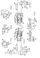
- the document feed-in device 11 (see Figure 1) is used on a typewriter of electronic type, having the usual paper platen 12, lower paper pressure rolls 13 and upper paper pressure rolls 14.
- the platen 12 is rotatable by a shaft 16, by means of an electric motor 17 (see Figure 7) of a line spacer device which is not shown in the drawings but which is substantially similar to that described in our published European patent application No EP 0 038 216.
- the lower pressure rolls 13 (see Figure 1) are supported in a manner known per se and are received in slots 18 in a lower paper pressure plate or guide bar 19, which is fixed to a support 21.
- the upper pressure rolls or bail rollers 14 are mounted slidably on a conventional bail bar 22 which is fixed to two paper pressure bail levers, being a left-hand lever 23 and a right-hand lever 24, which are disposed at the ends of the bar 22.
- Each lever 23 and 24 is pivoted on a spindle 26, 27 (see Figure 2) and comprises a pin 28, 29 co-operable with a spring 31, 32 (see Figure 1), and a lug 33, 34 co-operable with a fixed abutment 36, 37 (see Figure 2).
- Each spring 31, 32 (see Figure 1) is fitted between the respective pin 28, 29 of the lever 23, 24, and a pin 38, 39 (see Figure 2) which is fixed to the carriage of the machine to rotationally urge the respective lever 23, 24 in an anticlockwise direction, with each lever 23 and 24 being in a position of abutment with the pressure rolls 14 (see Figure 1) against the outside surface of the platen 12, when it is in the position shown in Figure 1.
- the left-hand pressure lever 23 comprises a second lug 41 which is connected by means of a pin or pivot 42 to an arm 43 of an actuating lever 44.
- the lever 44 has a suitably shaped bent slot 46 which slides on a fixed guide pin 47, and a lug 48 co-operable with a blade 49 of a switch 51 in a given operating position as described hereinafter.
- the right-hand pressure lever 24 comprises an upwardly projecting arm 52 which terminates with a handle portion 52 such that it can be gripped by an operator for positioning the device 11 during the operation of introducing or feeding in a document or sheet of typing paper 54.
- the operator by gripping the handle 53, causes the levers 23 and 24 to rotate in the clockwise direction (in Figure 1) against the force of the respective springs 31 and 32 until the pins 28 and 29 take up the position shown by the chain-dotted line indicated at 56.
- the levers 23 and 24 are in an unstable position, with the springs 31 and 32 at the dead centre position, and the actuating lever 44 with the lug 48 reaches the position shown in chain-dotted lines at 57.
- the operator rotates the levers 23 and 24 in the anticlockwise direction against the force of the springs 31 and 32 until the arrangement reaches the position indicated at 56 and, when the arrangement goes beyond that position, the springs 31 and 32 assist such rotary motion until the upper tolls 14 are stopped and held against the periphery of the paper platen 18.
- the switch 51 is connected to an input-output unit 61 (see Figure 7) which is controlled by a central unit 62 connected to memories 63 and a keyboard 64.
- the input-output unit 61 controls the clockwise and anticlockwise rotation and stopping of the electric motor 17 by means of three lines 66, 67 and 68 and an amplifier 69, and receives the information relating to the opened and closed conditions of the switch 51, by means of a line 71.
- the feed-in device 11 (see Figure 1) comprises an upper guide member 76 and which is mounted on the bar 22 and the levers 23 and 24, thus being movable with the bar 22 and the levers 23 and 24.
- the upper guide member 76 comprises a plate or bar member 77 which is disposed parallel to the platen 12 and which has two supports 78 and 79 (see Figure 2) at its ends.
- the supports 78 and 79 co-operate with corresponding sleeve portions 81 and 82 on the respective levers 23 and 24, and have two teeth 83 and 84 which can be received in corresponding seats 86 and 87 in the sleeve portions 81 and 82.
- the seats 86 and 87 are defined by two shoulders 88 and 89 which are capable of delimiting rotary movement of the teeth 83 and 84 (see Figure 2).
- Mounted on each sleeve portion 81 and 82 is a respective spring 91 and 92 having one end 93, 94 bearing against a shoulder or lug 96 and 97 on the respective sleeve portion 81 and 82, while the other end 98, 99 bears against an edge of the respective tooth 83 and 84 of the guide member 76.
- the two springs 91 and 92 are torsion type springs: one spring being right-handed and the other spring being left-handed, and being mounted in such a way that they normally urge the plate or bar member 77 in an anticlockwise direction (in Figure 1) and hold it in a condition of bearing with the teeth 83 and 84 against the shoulders 89 (see Figure 6). In that way, the member 77 is held at a slight spacing from the outside surface of the platen 12, as shown in Figure 6, for guiding the typing paper 54 and permitting it to pass be + ween the outside surface of the platen 12 and the plate or bar member 77.
- the described document feed-in device 11 is particularly suitable when the operator or user is required to type immediately at the topmost edge of the sheet of paper 54, for example when a cheque is to be made out, in which figures are to be typed is adjacent to the top edge thereof.
- the memory 63 (see Figure 7) and the central unit 62 contain particularised information which, depending on the type of document, causes the motor 17 to rotate by a predetermined amount in order to position the top edge at the typing point.
- the above-described document feed-in device 11 (see Figure 1) is particularly suitable for being fitted to machines in which the typing assembly is carried by a movable carriage and is mounted very close to the typing platen 12. That is the situation when the typing assembly comprises a "daisy wheel” type character carrier with flexible petals, as described in our British patent specification GB 2 030 076, or when the typing assembly is of the needle type.
- the plate or bar member 77 takes up the entire width of the platen and, in its operating position (see Figure 6) , with its lower edge immediately above the typing line.
- the plate or bar member 77 in its position 104, does not interfere with the top edge of the paper.
- the plate or bar member 77 in its position 102 has its lower edge below the top edge of the paper and it is only from that position 102 that the plate or bar member will be able to engage the top edge of the cheque 54, to position it adjacent to the typing platen 12. That therefore avoids any possibility of jaming or sticking as between the plate or bar member and the paper.
Landscapes
- Handling Of Sheets (AREA)
- Delivering By Means Of Belts And Rollers (AREA)
Applications Claiming Priority (2)
| Application Number | Priority Date | Filing Date | Title |
|---|---|---|---|
| IT6712382 | 1982-02-03 | ||
| IT67123/82A IT1155264B (it) | 1982-02-25 | 1982-02-25 | Introduttore di documenti |
Publications (3)
| Publication Number | Publication Date |
|---|---|
| EP0085568A2 true EP0085568A2 (fr) | 1983-08-10 |
| EP0085568A3 EP0085568A3 (en) | 1984-09-26 |
| EP0085568B1 EP0085568B1 (fr) | 1987-11-19 |
Family
ID=11299780
Family Applications (1)
| Application Number | Title | Priority Date | Filing Date |
|---|---|---|---|
| EP83300496A Expired EP0085568B1 (fr) | 1982-02-03 | 1983-02-01 | Dispositif pour l'introduction de documents dans une machine à écrire |
Country Status (4)
| Country | Link |
|---|---|
| US (1) | US4525089A (fr) |
| EP (1) | EP0085568B1 (fr) |
| DE (1) | DE3374531D1 (fr) |
| IT (1) | IT1155264B (fr) |
Cited By (2)
| Publication number | Priority date | Publication date | Assignee | Title |
|---|---|---|---|---|
| EP0226327A3 (en) * | 1985-11-12 | 1988-06-08 | Genicom Corporation | Paper-handling mechanism for a printer |
| FR2665115A1 (fr) * | 1990-07-24 | 1992-01-31 | Seikosha Kk | Dispositif a barre presse-papier pour imprimante. |
Families Citing this family (5)
| Publication number | Priority date | Publication date | Assignee | Title |
|---|---|---|---|---|
| DE3585546D1 (de) * | 1984-01-25 | 1992-04-16 | Tokyo Electric Co Ltd | Anordnung zur papierzufuhr fuer einen drucker. |
| US4714364A (en) * | 1984-08-10 | 1987-12-22 | Ricoh Company, Ltd. | Automatically returned paper ball assembly of a printer |
| JPS6149876A (ja) * | 1984-08-20 | 1986-03-11 | Brother Ind Ltd | 用紙送り装置 |
| CA1244371A (fr) * | 1984-08-31 | 1988-11-08 | Mitsuhiro Taketani | Dispositif d'impression |
| JPH0657464B2 (ja) * | 1985-04-09 | 1994-08-03 | ブラザー工業株式会社 | 印字装置 |
Family Cites Families (18)
| Publication number | Priority date | Publication date | Assignee | Title |
|---|---|---|---|---|
| US1682333A (en) * | 1928-08-28 | Typewriting machine | ||
| US1427909A (en) * | 1922-09-05 | Typewriting machine | ||
| US1024759A (en) * | 1911-10-27 | 1912-04-30 | Monarch Typewriter Co | Type-writing machine. |
| US1192577A (en) * | 1916-04-27 | 1916-07-25 | Remington Typewriter Co | Type-writing machine. |
| US1244011A (en) * | 1917-01-31 | 1917-10-23 | William A Lorenz | Paper control for type-writing machines. |
| US1900102A (en) * | 1927-06-25 | 1933-03-07 | Remington Typewriter Co | Typewriting machine |
| DE666470C (de) * | 1936-04-12 | 1938-10-20 | Wanderer Werke Vorm Winklhofer | Papierhalteschiene fuer schreibende Bueromaschinen |
| US2642172A (en) * | 1951-10-10 | 1953-06-16 | Felber Sidney | Erasing shield |
| FR1229593A (fr) * | 1959-07-15 | 1960-09-08 | Olympia Werke Ag | Réglette d'alignement pivotant hors de portée des caractères, utilisable sur les machines à calculer imprimeuses et sur les machines analogues |
| DE2526445A1 (de) * | 1975-06-13 | 1976-12-23 | Triumph Werke Nuernberg Ag | Papiereinwerfer |
| IT1160425B (it) * | 1978-07-18 | 1987-03-11 | Olivetti & Co Spa | Dispositivo di scrittura e/o correzione per macchine scriventi |
| US4266880A (en) * | 1978-09-26 | 1981-05-12 | International Business Machines Corporation | Paper insertion apparatus |
| US4215945A (en) * | 1978-12-26 | 1980-08-05 | International Business Machines Corporation | Paper feeding apparatus |
| US4211499A (en) * | 1978-12-26 | 1980-07-08 | International Business Machines Corporation | Paper feeding control apparatus |
| IT1130114B (it) * | 1980-04-15 | 1986-06-11 | Olivetti & Co Spa | Dispositivo di interlinea per macchine scriventi |
| IT1128976B (it) * | 1980-08-21 | 1986-06-04 | Olivetti & Co Spa | Testina di stampa a fili balistica |
| US4386864A (en) * | 1980-11-04 | 1983-06-07 | Wang Laboratories, Inc. | Selective paper insertion and feeding means for individual sheet printing apparatus |
| JPS5784885A (en) * | 1980-11-14 | 1982-05-27 | Usac Electronics Ind Co Ltd | Leading-end protruding method for slip form medium in printer |
-
1982
- 1982-02-25 IT IT67123/82A patent/IT1155264B/it active
-
1983
- 1983-02-01 EP EP83300496A patent/EP0085568B1/fr not_active Expired
- 1983-02-01 DE DE8383300496T patent/DE3374531D1/de not_active Expired
- 1983-02-03 US US06/463,493 patent/US4525089A/en not_active Expired - Fee Related
Cited By (2)
| Publication number | Priority date | Publication date | Assignee | Title |
|---|---|---|---|---|
| EP0226327A3 (en) * | 1985-11-12 | 1988-06-08 | Genicom Corporation | Paper-handling mechanism for a printer |
| FR2665115A1 (fr) * | 1990-07-24 | 1992-01-31 | Seikosha Kk | Dispositif a barre presse-papier pour imprimante. |
Also Published As
| Publication number | Publication date |
|---|---|
| US4525089A (en) | 1985-06-25 |
| EP0085568B1 (fr) | 1987-11-19 |
| EP0085568A3 (en) | 1984-09-26 |
| IT8267123A0 (it) | 1982-02-03 |
| DE3374531D1 (en) | 1987-12-23 |
| IT1155264B (it) | 1987-01-28 |
| IT8267123A1 (it) | 1983-08-25 |
Similar Documents
| Publication | Publication Date | Title |
|---|---|---|
| US4437780A (en) | Cylindrical platen printer with improved paper guide | |
| RU2120387C1 (ru) | Картридж принтера, принтер, устройства для перемещения бумаги | |
| CA1283809C (fr) | Plaque pour exercer une pression sur des enveloppes allant a l'affranchissement mecanique | |
| EP0085568A2 (fr) | Dispositif pour l'introduction de documents dans une machine à écrire | |
| EP0063590B1 (fr) | Insertion selective de papier et dispositif d'avancement pour une imprimante de feuilles individuelles | |
| US4565462A (en) | Paper loading apparatus for printer including plural feed paths | |
| GB746128A (en) | Improvements relating to rotary printing machines | |
| EP0118318B1 (fr) | Dispositif presseur pour papier dans les imprimantes | |
| US4211499A (en) | Paper feeding control apparatus | |
| US3264981A (en) | Tandem printer | |
| US4605324A (en) | Electronic typewriter with a device for zero positioning of a rotary character-carrying device | |
| US2758539A (en) | Sheet strippers for rotary duplicators | |
| US3414259A (en) | Gripper device for a sheet feeder of a printing press | |
| EP0313404B1 (fr) | Dispositif pour le chargement automatique du papier dans une imprimante ayant un mécanisme de commande pour l'arceau | |
| EP0139411B1 (fr) | Dispositif pour contrôler le mouvement rotatif d'une platine | |
| US2679801A (en) | Driving mechanism for sheet-feeding devices in duplicating and like machines | |
| GB1563210A (en) | Mechanism for moving tape to be printed | |
| US1874823A (en) | Typewriting machine | |
| EP0121382B1 (fr) | Imprimante en série | |
| US4722624A (en) | Control apparatus for paper pressure rollers of printing machines | |
| US5129750A (en) | Opening mechanism for a printer | |
| US2746590A (en) | Upper feed roll control means for typewriting and like machines | |
| US2971625A (en) | Repeat actuation arrangement for typewriters | |
| US3391775A (en) | Sheet forwarding mechanism | |
| US2872862A (en) | Symbol printing mechanisms in listing calculating machines and the like |
Legal Events
| Date | Code | Title | Description |
|---|---|---|---|
| PUAI | Public reference made under article 153(3) epc to a published international application that has entered the european phase |
Free format text: ORIGINAL CODE: 0009012 |
|
| AK | Designated contracting states |
Designated state(s): DE FR GB |
|
| PUAL | Search report despatched |
Free format text: ORIGINAL CODE: 0009013 |
|
| AK | Designated contracting states |
Designated state(s): DE FR GB |
|
| 17P | Request for examination filed |
Effective date: 19850305 |
|
| 17Q | First examination report despatched |
Effective date: 19860310 |
|
| GRAA | (expected) grant |
Free format text: ORIGINAL CODE: 0009210 |
|
| AK | Designated contracting states |
Kind code of ref document: B1 Designated state(s): DE FR GB |
|
| REF | Corresponds to: |
Ref document number: 3374531 Country of ref document: DE Date of ref document: 19871223 |
|
| ET | Fr: translation filed | ||
| PLBE | No opposition filed within time limit |
Free format text: ORIGINAL CODE: 0009261 |
|
| STAA | Information on the status of an ep patent application or granted ep patent |
Free format text: STATUS: NO OPPOSITION FILED WITHIN TIME LIMIT |
|
| 26N | No opposition filed | ||
| PGFP | Annual fee paid to national office [announced via postgrant information from national office to epo] |
Ref country code: FR Payment date: 19911223 Year of fee payment: 10 |
|
| PGFP | Annual fee paid to national office [announced via postgrant information from national office to epo] |
Ref country code: DE Payment date: 19920331 Year of fee payment: 10 |
|
| PGFP | Annual fee paid to national office [announced via postgrant information from national office to epo] |
Ref country code: GB Payment date: 19930125 Year of fee payment: 11 |
|
| PG25 | Lapsed in a contracting state [announced via postgrant information from national office to epo] |
Ref country code: FR Effective date: 19931029 |
|
| PG25 | Lapsed in a contracting state [announced via postgrant information from national office to epo] |
Ref country code: DE Effective date: 19931103 |
|
| REG | Reference to a national code |
Ref country code: FR Ref legal event code: ST |
|
| PG25 | Lapsed in a contracting state [announced via postgrant information from national office to epo] |
Ref country code: GB Effective date: 19940201 |
|
| GBPC | Gb: european patent ceased through non-payment of renewal fee |
Effective date: 19940201 |