EP0085570A2 - Schwingungsüberwachungsvorrichtung für Flugzeugmotoren - Google Patents
Schwingungsüberwachungsvorrichtung für Flugzeugmotoren Download PDFInfo
- Publication number
- EP0085570A2 EP0085570A2 EP83300499A EP83300499A EP0085570A2 EP 0085570 A2 EP0085570 A2 EP 0085570A2 EP 83300499 A EP83300499 A EP 83300499A EP 83300499 A EP83300499 A EP 83300499A EP 0085570 A2 EP0085570 A2 EP 0085570A2
- Authority
- EP
- European Patent Office
- Prior art keywords
- sampling
- digital
- frequency
- coupled
- filter
- Prior art date
- Legal status (The legal status is an assumption and is not a legal conclusion. Google has not performed a legal analysis and makes no representation as to the accuracy of the status listed.)
- Withdrawn
Links
- 238000012544 monitoring process Methods 0.000 title claims abstract description 9
- 238000005070 sampling Methods 0.000 claims abstract description 41
- 230000015654 memory Effects 0.000 claims abstract description 26
- 230000001133 acceleration Effects 0.000 claims description 4
- 238000006243 chemical reaction Methods 0.000 claims description 3
- 238000012545 processing Methods 0.000 claims description 2
- 230000000737 periodic effect Effects 0.000 claims 4
- 230000011664 signaling Effects 0.000 claims 4
- 230000004044 response Effects 0.000 claims 1
- 238000000034 method Methods 0.000 abstract description 17
- 230000008569 process Effects 0.000 abstract description 2
- 238000013500 data storage Methods 0.000 abstract 1
- 230000003750 conditioning effect Effects 0.000 description 22
- 238000010586 diagram Methods 0.000 description 8
- 230000000694 effects Effects 0.000 description 4
- 238000001914 filtration Methods 0.000 description 4
- 230000006870 function Effects 0.000 description 2
- 208000027418 Wounds and injury Diseases 0.000 description 1
- 230000002411 adverse Effects 0.000 description 1
- 238000010420 art technique Methods 0.000 description 1
- 230000008859 change Effects 0.000 description 1
- 230000001143 conditioned effect Effects 0.000 description 1
- 230000006378 damage Effects 0.000 description 1
- 230000001066 destructive effect Effects 0.000 description 1
- 238000001514 detection method Methods 0.000 description 1
- PCHJSUWPFVWCPO-UHFFFAOYSA-N gold Chemical compound [Au] PCHJSUWPFVWCPO-UHFFFAOYSA-N 0.000 description 1
- 239000010931 gold Substances 0.000 description 1
- 229910052737 gold Inorganic materials 0.000 description 1
- 230000005484 gravity Effects 0.000 description 1
- 208000014674 injury Diseases 0.000 description 1
- 238000009434 installation Methods 0.000 description 1
- 230000010354 integration Effects 0.000 description 1
- 238000012423 maintenance Methods 0.000 description 1
- 230000007257 malfunction Effects 0.000 description 1
- 238000012986 modification Methods 0.000 description 1
- 230000004048 modification Effects 0.000 description 1
- 230000008520 organization Effects 0.000 description 1
- 230000008439 repair process Effects 0.000 description 1
- 238000012552 review Methods 0.000 description 1
- 230000001629 suppression Effects 0.000 description 1
- 230000002889 sympathetic effect Effects 0.000 description 1
Images


Classifications
-
- G—PHYSICS
- G01—MEASURING; TESTING
- G01H—MEASUREMENT OF MECHANICAL VIBRATIONS OR ULTRASONIC, SONIC OR INFRASONIC WAVES
- G01H1/00—Measuring characteristics of vibrations in solids by using direct conduction to the detector
- G01H1/003—Measuring characteristics of vibrations in solids by using direct conduction to the detector of rotating machines
-
- G—PHYSICS
- G07—CHECKING-DEVICES
- G07C—TIME OR ATTENDANCE REGISTERS; REGISTERING OR INDICATING THE WORKING OF MACHINES; GENERATING RANDOM NUMBERS; VOTING OR LOTTERY APPARATUS; ARRANGEMENTS, SYSTEMS OR APPARATUS FOR CHECKING NOT PROVIDED FOR ELSEWHERE
- G07C3/00—Registering or indicating the condition or the working of machines or other apparatus, other than vehicles
Definitions
- the present invention relates to vibration monitoring systems and, more particularly, vibration monitoring systems for jet aircraft engines.
- the problem or incipient failure is a more serious one when the machine with the rotating component is an aircraft jet engine.
- the modern engine includes several concentrically mounted shafts, each rotating at a slightly different frequency.
- Each of the rotating shafts or spools can include a compressor- turbine assembly which in turn includes fan and turbine blades. In the intake stages the blades are used to compress incoming air, and in the output stages the blades drive the compressor.
- Machinery having massive rotating components such as jet aircraft engines but also including large motor generators, turbines and the like, may experience bearing failurs or may, through"problems of wear or accident, become unbalanced and impose unacceptable loads upon the bearing, and the shaft housings.
- Prior art techniques have utilized filters in an attempt to isolate the vibrations attributable to the engine components, and these filtered signals are then processed to provide a quantitative display that a trained observer could interpret. The observer, noting the amplitude over a period of time can then judge if a malfunction is threatened or if one exists.
- a tachometer is associated with each shaft and is used to control phase-locked loop frequency multipliers whose outputs are applied to monostable circuits which control conventional analog tracking filters, the output signals of which depend only on the amplitude of the basic frequency of the input signal from the integrater.
- analog circuits in general must be designed for specific applications, and, further, tend to be susceptible to noise and electrical disturbances which could adversely affect the integrity of the output signals. Further, the frequencies of interest, which range from 20 Hz to 200 Hz, are not easily accommodated is analog circuits.
- a system based upon a digital computer has been created ⁇ which converts the analog output of a transducer, such as an accelerometer, into digital signals.
- the tachometer signals are easily provided as a pulse train whose frequency is related to the frequency of the rotating component of interest.
- Standard digital components, including counters and memory devices, are utilized to generate a sampling pulse train, whose frequency is a predetermined, integral fraction of the frequency of the rotating component, so that a suitable number of samples of the accelerometer output can be digitized to represent adequately the quantities sensed by the transducer.
- a nonrecursive digital filter is created utilizing a memory in which coefficients are stored. Each digitized sample is processed through the digital filter to create a digitized output. The digital computer then converts the filter output to an RMS value which is converted in a digital to analog converter, and the resultant analog signal can be applied to drive a meter display.
- the apparatus can, through programming, be adapted to perform other functions. For example, vibrations at virtually any frequency of interest can be detected and displayed.
- In-flight balance determinations can be made as well as trend analysis for maintenance of the rotating component.
- the memory can store and retain instances of extreme vibrational amplitude or other transitory events for study and later analysis.
- the same apparatus can be adapted for different machinery, different frequencies, and the programmable digital filter can be reprogrammed to exhibit special or different characteristics.
- the digital computer provides the appropriate clock frequencies for tracking and performs the desired analysis.
- FIG. 1 there is shown.in block diagram form, a vibration analyzing system 10 which is adapted to operate and monitor the vibration of an aircraft jet engine.
- a plurality of inputs from accelerometers mounted on one or more jet engines are applied to an accelerometer signal conditioning and analog to digital converter unit 12.
- a plurality of tachometers, one monitoring each major rotating component of each jet engine to be monitored are applied to a tachometer signal conditioning and analog to digital converter unit 14.
- the resulting digital signals from the accelerometer signal conditioning unit 12 and the tachometer signal conditioning unit 14 are applied to a microprocessor-based data conditioning unit 16.
- an integration stage is included in the analog acceleration signal conditioning circuitry 12.
- the conditioned accelerometer signals still in analog form, are applied to a broad band analog filter and RMS converter 18 the output of which is applied to an analog to digital converter 20.
- the signals now in digital form, are supplied to the microprocessor-based signal conditioning unit 16.
- the microprocessor data conditioning unit 16 generates data sampling signals which are related to the tachometer input. As the rotation rates of the various components vary, the sampling rate must also vary, so that the same, predetermined number of samples per cycle are obtained.
- the data sampling signals are used to gate accelerometer signals into the analog to digital converter portion of the accelerometer signal conditioning unit 12.
- the digitized accelerometer signals from the accelerometer signal conditioning and A to D converting unit 12 are applied to a narrow band, nonrecursive digital filter network 22, the output of which is applied to the microprocessor-based data conditioning unit 16.
- the microprocessor-based data conditioning unit 16 supplies digital output signals representing desired information to an output signal conditioning circuit 24, which converts the digital signals to analog signals to drive appropriate display devices.
- the accelerometer output from the instruments on a particular jet engine is filtered at the rotational frequency of each of the major rotating components.
- the system of the present invention will measure the RMS velocity which can be scaled to any description such as peak or average value of vibration from each of the accelerometers at the frequency of each of the spools.
- the use of a nonrecursive digital filter enables a much narrower band width with substantial suppression of noise outside the pass band.
- FIG. 2 there is shown in a more detailed block diagram, the system 1U as adapted to operate in conjunction with a twin engine aircraft, each engine of which has three rotating spools, each capable of rotating at a different frequency.
- engine #1 has spools N 1 , N 2 and N 3 .
- accelerometers 1A and 1B Associated with engine #1 are accelerometers 1A and 1B.
- Engine #2 similarly, has rotating spools N 4 , N 5 and N 6 , and vibrations are detected by accelerometers 2A and 2B.
- the accelometer signal conditioning block 12 includes an integrating circuit as a part of the analog vibration signal conditioning circuitry 30 which, on several lines, applies velocity data to first and second switching devices 32, 34.
- the first switching device 32 applies selected analog signals to the broad band analog filter and RMS converter 18.
- the second switching device 34 applies analog data to a sample and hold circuit 36, which includes an analog to digital conversion capability.
- a programmable counter/rate generator 38 is controlled by the microprocessor 16 to sample the velocity signals at a predetermined rate, based upon the frequency of rotation.
- the sampling rate is 18 samples per rotational cycle, or a sample for each 20 degrees of rotation.
- the sampled analog signal is then converted into a digital signal which is applied to the narrow band non-recursive digital filter 22.
- the tachometer analog input data is applied to the tachometer signal conditioning block 14 which includes analog tachometer circuits 40 which are connected to a switch 42 for selecting a particular tachometer input.
- a frequency counter and prescaler 44 includes a programmable counter coupled to the microprocessor 16. The frequency counter and prescaler 44 converts the tachometer input, generally a multiple of the rotational frequency, to a signal train having a rate more nearly equal to the actual rotating frequency.
- the constant is supplied by the microprocessor 16.
- the output of the prescaler 44 would then be a pulse train at either the frequency of rotation or, a predetermined multiple of that frequency.
- the microprocessor 16 utilizes the information supplied by the frequency counter and prescaler 44 to determine the constant that must be inserted into the rate generator 38 so that the sampling intervals will represent a data input every 20 degrees of rotation.
- the oucput of the digital filter 22 is applied to the microprocessor 16 for data comparison and to check the validity of the system.
- the microprocessor 16 also can convert digital filter data to RMS or such other convenient description data such as average or peak value for driving display devices.
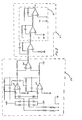
- the accelerometer signal conditioning circuits 12 of Figure 1 are illustrated in greater detail in Figure 3.
- the circuits for one accelerometer are illustrated and it will be understood that, depending upon the circumstances, either the circuit can be duplicated and dedicated to each accelerometer, or a single circuit can be shared among several accelerometers.
- a differential output piezoelectric accelerometer is utilized to detect vibration.
- a general characteristic of such an accelerometer is that the output signal is a charge which must be converted to a voltage.
- Illustrated is a conventional charge amplifier 52 which includes a pair of differential amplifiers 54, 56 driving the two inputs of a third differential amplifier 58, thereby converting the input charge signal to a low impedance, single ended millivolt output.
- a conventional integrater circuit 59 is connected to the output of the charge amplifier 52, which has the effect of changing the acceleration representing signals into velocity representing signals.
- a simple, low pass filter circuit 60 is added to provide attenuation of frequencies above 200 Hz and to avoid any foldback effects resulting from the sampling of the input at the predetermined rate.
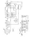
- the tachometer signals are treated in the tachometer signal conditioning circuits 14 which are described in greater detail in Figure 4.
- the several tachometer inputs are applied to a switching multiplexer 62 which, under control of the microprocessor 16, selects one of the tachometer inputs.
- the tachometer input is frequently a multiple of the frequency of rotation of the component under examination, it is preferable to divide out such multiple to provide a pulse train that is at or near the frequency of the rotating component. For example, if the tachometer provides a frequency, Fin, of 60 pulses per revolution of a spool, then, in this application, the constant K 1 would be equal to 60.
- a prescaler 64 is adapted to have a constant K inserted by the microprocessor 16. The constant is then a fixed count by which the input signal Fin is divided to provide a pulse train output of approximately the frequency of the rotating component. This pulse train is applied to gate a frequency counter 66, which is connected to count a clock of predetermined frequency.
- a 2 MHz clock generator 68 is counted down in a programmable counter 70.
- the programmable counter 70 can be preset with numbers supplied by the microprocessor 16, so that the output of the counter 70 will be a pulse train of any desired frequency that is less than 2 MHz. If a constant, such as 200, is inserted into the programmable counter 70, the counter 70 pulse train output will be at a rate of 10,000 pulses per second, with a pulse period of .1 ms.
- this clock pulse train is gated by the output of the prescaler 64, then a number will be generated that is representative of and corresponds to the period of the rotating element expressed as a count.
- the frequency counter 66 can be arranged under the control of the microprocessor 16 so that only a single period need be timed.
- the number, representing the time required for one rotational interval is applied to the microprocessor 16. Since a sampling rate of 18 samples per rotation is desired, a sampling pulse train is needed whose period is 1/18th the period of the rotating component.
- a number K 2 is then retrieved from the microprocessor data conditioning unit 16 which can then be used to count down a clock to provide a pulse train Fs that is the signal of the desired sampling rate.
- the number K 2 is inserted into a sampling counter 72 which receives the raw 2 MHZ clock from the clock generator 68.
- the output of the sampling counter 72 is now a pulse train whose frequency, Fs, is 18 times the frequency of the rotating component.
- the sampling pulse train Fs is used to control the analog-to- digital circuits 36 that digitize the velocity representing analog signals, which are derived from the accelerometers.
- the sign and magnitude of the velocity signal can be quantized and is available, in digital form, for ditigal filtering.
- the system can easily be programmed to accommodate various tachometers so that a pulse train, generally at the frequency of rotation of the rotating component of interest, can be available. Similarly, the period of rotation can be expressed in varying degrees of precision by appropriate selection of the constant which is used as the divisor in the programmable counter 70 that divides down the high frequency clock.
- microprocessor 16 can do either table lookups or computations, an appropriate constant can be entered into the sampling counter 72, so that the high frequency clock can be divided down to the desired sampling frequency, that has been predetermined to be 18 times the frequency of rotation of the component of interest.
- phase lock loop multiplier to process the tachometer inputs
- Other techniques of the prior art such as the use of a phase lock loop multiplier to process the tachometer inputs, would require that a different multiplier circuit be designed for every possible tachometer installation that provided a different number of pulses per revolution. Further, the operating frequencies encountered generally tend to be far below the frequencies at which a phase lock loop multiplier is effective and reliable.
- the filter 74 includes a plurality of delay elements 76 each of which can store one sample, expressed in digital form of the input signal information.
- the filter includes M delay elements 76 where M is a number sufficiently large to produce reasonable filtering. The sample in each delay block is multiplied by a different weighting function in a multiplier element 78.
- each multiplier element 78 is accumulated in a summing register 80. An output is then avaialble after each sampling. However, because the filter is shared among the several components that are being monitored, at least 256 samples are required before the data is reliable and representative.
- coefficients are selected which provide a gain of two or more in the digital filter.
- the signal output from the filter is inhibited until a full number of valid samples have been stored in the delay elements 76.
- the filter includes 256 stages, accordingly the output of the summing register 80 is suppressed until 256 samples have been received from a given sensor, are stored in the delay element 96 and processed through the multiplier elements 78.
- each succeeding sample can result in a meaningful filter output which can be applied to the microprocessor 16 for further analysis.
- the output can also be converted to an analog signal and applied to drive a cockpit display, in the case of an aircraft.
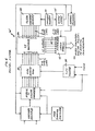
- a nonrecursive digital filter 74' useful in the present system is illustrated in detail in Figure 6.
- the digitized sample is applied to a first-in first-out, random access memory 82 in which a predetermined number of samples are stored.
- a "pointer" 84 is an addressing counter which can access each of the memory locations to successively present the contents of each to an X-Y Multiplier and Summation circuit 86.
- the pointer 84 is arranged so that it "rests” after each cycle at a different address, so that each new data sample can be stored in a different location.
- the stored values from a "prior” cycle will be discarded and replaced by updating samples.
- a second, Constant storage memory 88 of a "size" equal to the number of stages in the digital filter, stores the various coefficients that are used in achieving the digital filter.
- a constant pointer 90 or counter is used to cycle through the various address locations of the constant memory 88.
- each location of the random access memory 82 and the constant memory 88 is addressed, their contents are applied to the multiplier 86 and the product of the two inputs is accumulated.
- each stored value in the random access memory 82 will be multiplied by a different constant in the constant memory 88.
- a cycle is completed and the sum of the products is transferred to a filter output storage element 92 which in turn, applies the resultant quantity to the microprocessor 16 and also to a digital to analog converter for presentation to the display circuits.
- the random access memory pointer 84 includes a count which remains constant through a complete cycle of memory addresses. This fixed number, however, is changed by one from cycle to cycle, which has the effect of presenting the address holding the "oldest" value so that it can be replaced by the newest value from the detector circuit.
- the constant pointer 90 merely recycles. It has the effect of multiplying each stored sample with a different coefficient, so long as that sample remains in the memory.
- the random access memory 82 is doubled in size to accommodate samples from both accelerometers.
- a ripple carry element 94 signals the completion of each cycle through the constant memory 88.
- the ripple signal is applied to the switching systems and the sampler circuit as well as the addressing portions of the random access memory pointer circuit 84 so that a second, substantially duplicate memory stores the signals from the second accelerometer.
- the stored number within the pointer 84 is then changed only after both a first cycle involving a sample from the first accelerometer and a second cycle, involving a sample from the second accelerometer have been completed.
- Appropriate information signals are provided to the microprocessor 16 so that the resultant data from the fiter output elements 92 can be correctly interpreted.
- the use of a memory to store the coefficients defining the digital filter, permit the coefficients to be easily changed or modified, depending upon the properties desired in the nonrecursive digital filter.
- the filter may be considered as a 256 sample delay line which, if 18 samples per cycle are utilized, can simultaneously hold approximately 14-1/4 rotational cycles of sensor information.
- These sensors' output signals include sign as well as magnitude. Therefore the summation of all of the samples should substantially cancel all random noise excursions and accentuate recurring perturbations.
- Digital techniques also permit the use of a variety of tachometer and frequency determining techniques so that a tachometer which operates at many times the frequency of the rotating ccmpo- nent can easily be accommodated in the present system and a pulse trained substantially at the frequency of rotation can be easily created.
- a pair of accelerometers can easily be employed since simple switching techniques can enable alternate sampling of the-acceler- o ⁇ eter signals.
- the nonrecursive digital filter can easily be constructed to accommodate signals from more than one sensor and well known multiplexing techniques permit the digital filter to be time shared between a pair of collocated accelerometers. Further, if the system is installed in a multi-engine aircraft, then each of the engines and their several "spools" can be accommodated with no particular change in apperatus.
Landscapes
- Physics & Mathematics (AREA)
- General Physics & Mathematics (AREA)
- Measurement Of Mechanical Vibrations Or Ultrasonic Waves (AREA)
Applications Claiming Priority (2)
| Application Number | Priority Date | Filing Date | Title |
|---|---|---|---|
| US06/344,561 US4488240A (en) | 1982-02-01 | 1982-02-01 | Vibration monitoring system for aircraft engines |
| US344561 | 1982-02-01 |
Publications (2)
| Publication Number | Publication Date |
|---|---|
| EP0085570A2 true EP0085570A2 (de) | 1983-08-10 |
| EP0085570A3 EP0085570A3 (de) | 1984-06-06 |
Family
ID=23351040
Family Applications (1)
| Application Number | Title | Priority Date | Filing Date |
|---|---|---|---|
| EP83300499A Withdrawn EP0085570A3 (de) | 1982-02-01 | 1983-02-01 | Schwingungsüberwachungsvorrichtung für Flugzeugmotoren |
Country Status (2)
| Country | Link |
|---|---|
| US (1) | US4488240A (de) |
| EP (1) | EP0085570A3 (de) |
Cited By (8)
| Publication number | Priority date | Publication date | Assignee | Title |
|---|---|---|---|---|
| GB2159952A (en) * | 1984-05-22 | 1985-12-11 | Micro Control Tech Ltd | Analysing helicopter rotor performance |
| GB2209397A (en) * | 1987-10-02 | 1989-05-10 | Servo Corp Of America | Acoustic detection of bearing defects |
| WO1990009644A1 (en) * | 1989-02-07 | 1990-08-23 | Smiths Industries Public Limited Company | Monitoring |
| EP0339833A3 (de) * | 1988-04-28 | 1991-05-15 | Kaman Aerospace Corporation | Fernkontrollsystem für Lasten |
| GB2248110A (en) * | 1990-09-19 | 1992-03-25 | Rolls Royce Plc | Vibration analysis system for a multi-shaft turbine |
| WO1996030649A1 (de) * | 1995-03-29 | 1996-10-03 | Leybold Vakuum Gmbh | Umwälzgebläse, vakuumpumpe oder dergleichen |
| EP0693176A4 (de) * | 1993-04-09 | 1997-03-05 | Monitoring Tech Corp | Verfahren und vorrichtung zur erfassung und analyse von fehlern an lagern und anderen gleitend rotierenden komponenten |
| CN119595293A (zh) * | 2024-12-24 | 2025-03-11 | 中国北方发动机研究所 | 一种发动机台架试验振动监测及故障诊断系统 |
Families Citing this family (59)
| Publication number | Priority date | Publication date | Assignee | Title |
|---|---|---|---|---|
| FR2539874B1 (fr) * | 1983-01-20 | 1985-07-05 | Alsthom Atlantique | Systeme de surveillance de l'endommagement en torsion d'une ligne d'arbres composee d'une machine entrainante et d'une machine entrainee |
| JPS59174732A (ja) * | 1983-03-24 | 1984-10-03 | Mitsubishi Electric Corp | ギアユニツトの異常判定装置 |
| JPS59178357A (ja) * | 1983-03-29 | 1984-10-09 | Mitsubishi Electric Corp | 歯車の異常音検出装置 |
| US4608650A (en) * | 1983-08-09 | 1986-08-26 | Becton Dickinson And Company | Imbalance measuring system and method |
| US4707779A (en) * | 1984-11-20 | 1987-11-17 | Measurex Corporation | Process for controlling a parameter based upon filtered data |
| IT1187446B (it) * | 1985-06-18 | 1987-12-23 | Consiglio Nazionale Ricerche | Dispositivo per separare il segnale dal rumore e dal contributo di fondo,particolarmente per strumenti elettrochimici computerizzati |
| US4908785A (en) * | 1985-08-16 | 1990-03-13 | The Boeing Company | Data compression method for telemetry of vibration data |
| US4643023A (en) * | 1985-11-01 | 1987-02-17 | Capps David F | Vibration testing apparatus |
| GB8605152D0 (en) * | 1986-03-03 | 1986-04-09 | Hughes Ltd Stewart | Digital tachometer |
| CH672374A5 (de) * | 1986-11-04 | 1989-11-15 | Bbc Brown Boveri & Cie | |
| US4885707A (en) * | 1987-02-19 | 1989-12-05 | Dli Corporation | Vibration data collecting and processing apparatus and method |
| US4937758A (en) * | 1987-09-04 | 1990-06-26 | Technology Integration And Development Group, Inc. | Method and apparatus for reducing vibration over the full operating range of a rotor and a host device |
| JP2814241B2 (ja) * | 1987-09-25 | 1998-10-22 | 株式会社ブリヂストン | 振動制御装置 |
| US4912661A (en) * | 1987-12-01 | 1990-03-27 | Hewlett-Packard Company | Tracking and resampling method and apparatus for monitoring the performance of rotating machines |
| US5473555A (en) * | 1988-08-18 | 1995-12-05 | Hewlett-Packard Company | Method and apparatus for enhancing frequency domain analysis |
| US5033305A (en) * | 1990-01-08 | 1991-07-23 | Westinghouse Electric Corp. | Digital torsionmeter |
| US5172325A (en) * | 1990-08-02 | 1992-12-15 | The Boeing Company | Method for balancing rotating machinery |
| US5221185A (en) * | 1991-08-05 | 1993-06-22 | General Electric Company | Method and apparatus for synchronizing rotating machinery to reduce noise |
| GB9309086D0 (en) * | 1993-05-01 | 1993-06-16 | Eaton Corp | Instrumentation power supply and read unit |
| US5477730A (en) * | 1993-09-07 | 1995-12-26 | Carter; Duncan L. | Rolling element bearing condition testing method and apparatus |
| US5586065A (en) * | 1994-05-31 | 1996-12-17 | The Boeing Company | Method and apparatus for minimizing aircraft cabin noise |
| US5551650A (en) * | 1994-06-16 | 1996-09-03 | Lord Corporation | Active mounts for aircraft engines |
| US5576977A (en) * | 1995-04-27 | 1996-11-19 | Alarm Device Manufacturing Company | Filter for eliminating the effects of fluorescent lights on microwave transceivers |
| US5825657A (en) * | 1996-02-23 | 1998-10-20 | Monitoring Technology Corporation | Dynamic, non-uniform clock for resampling and processing machine signals |
| US6027239A (en) * | 1997-04-30 | 2000-02-22 | Endevco Corporation | On-board engine trim balance display and interface |
| US6026348A (en) * | 1997-10-14 | 2000-02-15 | Bently Nevada Corporation | Apparatus and method for compressing measurement data correlative to machine status |
| US5934610A (en) * | 1997-10-14 | 1999-08-10 | Endevco Corporation | Vibration monitoring system for multiple aircraft engines |
| US6507804B1 (en) | 1997-10-14 | 2003-01-14 | Bently Nevada Corporation | Apparatus and method for compressing measurement data corelative to machine status |
| US6044700A (en) * | 1997-10-14 | 2000-04-04 | Endevco Corporation | Aircraft equipment configuration identification interface guide |
| US5997360A (en) * | 1997-10-14 | 1999-12-07 | Gen-Kuong; Fernando Francisco | Aircraft equipment configuration identification interface |
| US6098022A (en) * | 1997-10-17 | 2000-08-01 | Test Devices, Inc. | Detecting anomalies in rotating components |
| US6904371B2 (en) * | 1997-10-17 | 2005-06-07 | Test Devices, Inc. | Method and apparatus for measuring rotor unbalance |
| JP3810615B2 (ja) | 2000-05-18 | 2006-08-16 | 三菱重工業株式会社 | タービンの遠隔制御方法及びシステム |
| ATE508533T1 (de) * | 2001-03-03 | 2011-05-15 | Optimum Power Technology Lp | Anordnung und verfahren zur abtastfrequenz- abhängigen einstellung einer filterfrequenz |
| IL144010A (en) * | 2001-06-26 | 2006-04-10 | Engines Pdm Ltd | Universal diagnostic method and system for engines |
| US7027953B2 (en) * | 2002-12-30 | 2006-04-11 | Rsl Electronics Ltd. | Method and system for diagnostics and prognostics of a mechanical system |
| US6763312B1 (en) | 2003-01-11 | 2004-07-13 | Dynamic Measurement Consultants, Llc | Multiple discriminate analysis and data integration of vibration in rotation machinery |
| RU2250494C1 (ru) * | 2003-10-02 | 2005-04-20 | Федеральное государственное унитарное предприятие "Центральный институт авиационного моторостроения им. П.И. Баранова" | Аппаратно-программное устройство (апу) для многоканального преобразования и регистрации аналоговых сигналов |
| US7693643B2 (en) * | 2005-02-14 | 2010-04-06 | Honeywell International Inc. | Fault detection system and method for turbine engine fuel systems |
| FR2898411B1 (fr) * | 2006-03-08 | 2008-05-16 | Inst Francais Du Petrole | Methode d'estimation en temps reel de parametres de combustion moteur a partir de signaux vibratoires |
| US7606673B2 (en) * | 2006-05-01 | 2009-10-20 | Dynamic Measurement Consultants, Llc | Rotating bearing analysis and monitoring system |
| US20070272023A1 (en) * | 2006-05-23 | 2007-11-29 | Honeywell International Inc. | Electronic vibration sensor |
| US8297123B2 (en) * | 2009-07-30 | 2012-10-30 | General Electric Company | Detection of anomalous movement in a reciprocating device |
| FR2953289B1 (fr) * | 2009-11-30 | 2012-04-27 | Snecma | Procede et dispositif de surveillance de vibrations en torsion d'un arbre rotatif d'une turbomachine. |
| US9243970B2 (en) * | 2012-11-30 | 2016-01-26 | Pratt & Whitney Canada Corp. | Method and system for integrating gas turbine trim balancing system into electronic engine controls |
| US10125636B2 (en) | 2016-02-12 | 2018-11-13 | United Technologies Corporation | Bowed rotor prevention system using waste heat |
| US10508567B2 (en) | 2016-02-12 | 2019-12-17 | United Technologies Corporation | Auxiliary drive bowed rotor prevention system for a gas turbine engine through an engine accessory |
| US10040577B2 (en) | 2016-02-12 | 2018-08-07 | United Technologies Corporation | Modified start sequence of a gas turbine engine |
| US9664070B1 (en) | 2016-02-12 | 2017-05-30 | United Technologies Corporation | Bowed rotor prevention system |
| US10443505B2 (en) * | 2016-02-12 | 2019-10-15 | United Technologies Corporation | Bowed rotor start mitigation in a gas turbine engine |
| US10508601B2 (en) | 2016-02-12 | 2019-12-17 | United Technologies Corporation | Auxiliary drive bowed rotor prevention system for a gas turbine engine |
| US10443507B2 (en) | 2016-02-12 | 2019-10-15 | United Technologies Corporation | Gas turbine engine bowed rotor avoidance system |
| US10125691B2 (en) | 2016-02-12 | 2018-11-13 | United Technologies Corporation | Bowed rotor start using a variable position starter valve |
| US10174678B2 (en) | 2016-02-12 | 2019-01-08 | United Technologies Corporation | Bowed rotor start using direct temperature measurement |
| US10436064B2 (en) | 2016-02-12 | 2019-10-08 | United Technologies Corporation | Bowed rotor start response damping system |
| US10539079B2 (en) | 2016-02-12 | 2020-01-21 | United Technologies Corporation | Bowed rotor start mitigation in a gas turbine engine using aircraft-derived parameters |
| US10358936B2 (en) | 2016-07-05 | 2019-07-23 | United Technologies Corporation | Bowed rotor sensor system |
| US10444196B2 (en) | 2017-09-20 | 2019-10-15 | Fisher Controls International Llc | Bandwidth-selectable acoustic emission apparatus and methods for transmitting time-averaged signal data |
| CN111830137B (zh) * | 2020-07-23 | 2023-04-18 | 中国舰船研究设计中心 | 一种隔振器水下隔振效果测试系统及评估方法 |
Family Cites Families (19)
| Publication number | Priority date | Publication date | Assignee | Title |
|---|---|---|---|---|
| US3449553A (en) * | 1965-08-23 | 1969-06-10 | United Geophysical Corp | Computer for determining the correlation function of variable signals |
| US3639848A (en) * | 1970-02-20 | 1972-02-01 | Electronic Communications | Transverse digital filter |
| US3816722A (en) * | 1970-09-29 | 1974-06-11 | Nippon Electric Co | Computer for calculating the similarity between patterns and pattern recognition system comprising the similarity computer |
| US3717756A (en) * | 1970-10-30 | 1973-02-20 | Electronic Communications | High precision circulating digital correlator |
| US3708746A (en) * | 1971-11-08 | 1973-01-02 | Univ Iowa State Res Found Inc | System for spectrum analysis including digital filter with variable sampling rate |
| US3758758A (en) * | 1972-03-10 | 1973-09-11 | United Aircraft Corp | Weighting rotational statistical vibration analysis employing sidebands and/or |
| US3733892A (en) * | 1972-04-03 | 1973-05-22 | Northrop Corp | Synchronous vibrational analyzer for rotating machinery |
| US3783680A (en) * | 1972-07-12 | 1974-01-08 | Atomic Energy Commission | Multipoint vibration monitoring system |
| US4010637A (en) * | 1975-10-06 | 1977-03-08 | Lockheed Aircraft Corporation | Machine vibration monitor and method |
| GB2003690A (en) * | 1977-08-05 | 1979-03-14 | Univ Surrey | Digital processing |
| US4166249A (en) * | 1978-02-15 | 1979-08-28 | Honeywell Inc. | Digital frequency-lock circuit |
| JPS54111871A (en) * | 1978-02-22 | 1979-09-01 | Hitachi Ltd | Frequency detecting method |
| US4181962A (en) * | 1978-02-27 | 1980-01-01 | The United States Of America As Represented By The Secretary Of The Navy | Digital programmable timing device |
| US4171522A (en) * | 1978-03-22 | 1979-10-16 | Real Time Systems, Inc. | Electronic angular position encoder apparatus |
| US4218752A (en) * | 1978-04-11 | 1980-08-19 | Texas Instruments Incorporated | Charge-transfer programmable filter |
| FR2447646A1 (fr) * | 1979-01-29 | 1980-08-22 | Materiel Telephonique | Filtre numerique transversal pour traitement en temps partage sur plusieurs canaux |
| US4213114A (en) * | 1979-03-07 | 1980-07-15 | Vibro-Meter Sa | Vibration monitoring system for an aircraft engine |
| JPS5631327A (en) * | 1979-08-24 | 1981-03-30 | Hitachi Ltd | Method of diagnosing vibration of rotary machine |
| US4423381A (en) * | 1981-01-16 | 1983-12-27 | Cincinnati Electronics Corporation | Pulse control circuit |
-
1982
- 1982-02-01 US US06/344,561 patent/US4488240A/en not_active Expired - Fee Related
-
1983
- 1983-02-01 EP EP83300499A patent/EP0085570A3/de not_active Withdrawn
Cited By (10)
| Publication number | Priority date | Publication date | Assignee | Title |
|---|---|---|---|---|
| GB2159952A (en) * | 1984-05-22 | 1985-12-11 | Micro Control Tech Ltd | Analysing helicopter rotor performance |
| GB2209397A (en) * | 1987-10-02 | 1989-05-10 | Servo Corp Of America | Acoustic detection of bearing defects |
| GB2209397B (en) * | 1987-10-02 | 1991-12-11 | Servo Corp Of America | On-line acoustic detection of bearing defects |
| EP0339833A3 (de) * | 1988-04-28 | 1991-05-15 | Kaman Aerospace Corporation | Fernkontrollsystem für Lasten |
| WO1990009644A1 (en) * | 1989-02-07 | 1990-08-23 | Smiths Industries Public Limited Company | Monitoring |
| GB2248110A (en) * | 1990-09-19 | 1992-03-25 | Rolls Royce Plc | Vibration analysis system for a multi-shaft turbine |
| GB2248110B (en) * | 1990-09-19 | 1994-08-31 | Rolls Royce Plc | Engine vibration analysis system for a multi shaft turbine |
| EP0693176A4 (de) * | 1993-04-09 | 1997-03-05 | Monitoring Tech Corp | Verfahren und vorrichtung zur erfassung und analyse von fehlern an lagern und anderen gleitend rotierenden komponenten |
| WO1996030649A1 (de) * | 1995-03-29 | 1996-10-03 | Leybold Vakuum Gmbh | Umwälzgebläse, vakuumpumpe oder dergleichen |
| CN119595293A (zh) * | 2024-12-24 | 2025-03-11 | 中国北方发动机研究所 | 一种发动机台架试验振动监测及故障诊断系统 |
Also Published As
| Publication number | Publication date |
|---|---|
| US4488240A (en) | 1984-12-11 |
| EP0085570A3 (de) | 1984-06-06 |
Similar Documents
| Publication | Publication Date | Title |
|---|---|---|
| US4488240A (en) | Vibration monitoring system for aircraft engines | |
| US4608650A (en) | Imbalance measuring system and method | |
| US3758758A (en) | Weighting rotational statistical vibration analysis employing sidebands and/or | |
| US4887468A (en) | Nonsynchronous turbine blade vibration monitoring system | |
| Goldman | Vibration spectrum analysis: a practical approach | |
| US5895857A (en) | Machine fault detection using vibration signal peak detector | |
| EP0179618B1 (de) | Gerät zur Detektion von Turbinenschaufelschwingungen | |
| US4683542A (en) | Vibration monitoring apparatus | |
| US5445028A (en) | Dynamic digital tracking filter | |
| US4419897A (en) | Apparatus for harmonic oscillation analysis | |
| US3731526A (en) | Variable center frequency filter | |
| US5069071A (en) | Vibration monitoring in the frequency domain with a capacitive accelerometer | |
| KR920015021A (ko) | 동기식 블레이드 진동을 감시하는 시스템 및 방법 | |
| US20120312099A1 (en) | Rotating blade analysis | |
| AU2001248388B2 (en) | Method of determining speed of rotation of a motor and a computer software product to carry out the method | |
| AU2001248388A1 (en) | Method of determining speed of rotation of a motor and a computer software product to carry out the method | |
| US4506551A (en) | Transducer selecting system | |
| JPH04270935A (ja) | 機械の回転部分の運動状態をモニターする方法及び装置 | |
| US20070090961A1 (en) | Method and system for detecting and measuring the disturbances in terms of frequency of the rate of rotation of a rotor | |
| GB2248110A (en) | Vibration analysis system for a multi-shaft turbine | |
| US3220247A (en) | Vibration vector measurement and display apparatus | |
| JP2572530B2 (ja) | 振動スペクトルモニタリング装置、並びにヘルスモニタリング方法及び装置 | |
| US5031459A (en) | Turbine generator shaft torsion monitor | |
| EP0246637A2 (de) | Verfahren zur Überwachung von Schwingungen in rotierenden Geräten | |
| JPH02130429A (ja) | 機械の異常診断方法 |
Legal Events
| Date | Code | Title | Description |
|---|---|---|---|
| PUAI | Public reference made under article 153(3) epc to a published international application that has entered the european phase |
Free format text: ORIGINAL CODE: 0009012 |
|
| AK | Designated contracting states |
Designated state(s): BE CH DE FR GB IT LI NL SE |
|
| 17P | Request for examination filed |
Effective date: 19830907 |
|
| PUAL | Search report despatched |
Free format text: ORIGINAL CODE: 0009013 |
|
| AK | Designated contracting states |
Designated state(s): BE CH DE FR GB IT LI NL SE |
|
| AK | Designated contracting states |
Designated state(s): BE CH DE FR GB IT LI NL SE |
|
| STAA | Information on the status of an ep patent application or granted ep patent |
Free format text: STATUS: THE APPLICATION IS DEEMED TO BE WITHDRAWN |
|
| 18D | Application deemed to be withdrawn |
Effective date: 19860108 |
|
| RIN1 | Information on inventor provided before grant (corrected) |
Inventor name: RAY, DAVID J. Inventor name: KAPADIA, NIKUL S. |