EP0085737A2 - Dispositif d'un miroir du type à télécommande électrique - Google Patents
Dispositif d'un miroir du type à télécommande électrique Download PDFInfo
- Publication number
- EP0085737A2 EP0085737A2 EP82103447A EP82103447A EP0085737A2 EP 0085737 A2 EP0085737 A2 EP 0085737A2 EP 82103447 A EP82103447 A EP 82103447A EP 82103447 A EP82103447 A EP 82103447A EP 0085737 A2 EP0085737 A2 EP 0085737A2
- Authority
- EP
- European Patent Office
- Prior art keywords
- mirror
- threaded rod
- ball
- boss portion
- mirror body
- Prior art date
- Legal status (The legal status is an assumption and is not a legal conclusion. Google has not performed a legal analysis and makes no representation as to the accuracy of the status listed.)
- Granted
Links
Images






Classifications
-
- B—PERFORMING OPERATIONS; TRANSPORTING
- B60—VEHICLES IN GENERAL
- B60R—VEHICLES, VEHICLE FITTINGS, OR VEHICLE PARTS, NOT OTHERWISE PROVIDED FOR
- B60R1/00—Optical viewing arrangements; Real-time viewing arrangements for drivers or passengers using optical image capturing systems, e.g. cameras or video systems specially adapted for use in or on vehicles
- B60R1/02—Rear-view mirror arrangements
- B60R1/06—Rear-view mirror arrangements mounted on vehicle exterior
-
- B—PERFORMING OPERATIONS; TRANSPORTING
- B60—VEHICLES IN GENERAL
- B60R—VEHICLES, VEHICLE FITTINGS, OR VEHICLE PARTS, NOT OTHERWISE PROVIDED FOR
- B60R1/00—Optical viewing arrangements; Real-time viewing arrangements for drivers or passengers using optical image capturing systems, e.g. cameras or video systems specially adapted for use in or on vehicles
- B60R1/02—Rear-view mirror arrangements
- B60R1/06—Rear-view mirror arrangements mounted on vehicle exterior
- B60R1/062—Rear-view mirror arrangements mounted on vehicle exterior with remote control for adjusting position
- B60R1/07—Rear-view mirror arrangements mounted on vehicle exterior with remote control for adjusting position by electrically powered actuators
- B60R1/072—Rear-view mirror arrangements mounted on vehicle exterior with remote control for adjusting position by electrically powered actuators for adjusting the mirror relative to its housing
Definitions
- the present invention relates to an electric remote control mirror apparatus for motor vehicles.
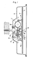
- Fig. 1 is a longitudinal cross sectional view
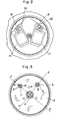
- Fig. 2 a cross sectional view as seen in the direction of the arrow II-II in Fig. 1
- Fig. 3 a cross sectional view as seen in the direction of the arrow III-III in Fig. 1
- Fig. 4 a cross sectional view as seen in the direction of the arrow IV-IV in Fig. 1.
- a mirror body 2 fixing a mirror 1 is pivotably supported through a pivot connection 4 with respect to a mirror housing 3.
- the line X-X' passing the center of the pivot connection 4 perpendicularly crosses the line Y-Y' passing the center.
- Boss portion 6 for a ball joint 5 is integrally pormed on the mirror body 2 on each of the above two lines.
- the boss portion 6 is rearwardly extended to hold the ball joint 5 as shown in Fig. 1.
- the threaded rod 8 having a ball 7 for the ball joint 5 has a male screw on the peripheral surface thereof, and the threaded rod 8 can be screwed into a female screw provided on a gear 9, the gear 9 being rotatably mounted in a screw member 10.
- the screw members 10, 10 are rotated to move the threaded rod 8 forwardly or backwardly thereby to incline the mirror body 2.
- the mirror body 2 is rotatably moved around the line Y-Y', and similarly the mirror body 2 is rotatably moved around the line X-X' by the movement of the threaded rod 8 connected to the ball joint 5 on the line X-X' of Fig. 3.
- Fig. 4 is a cross sectional view as seen in the direction of the arrow IV-IV of Fig. 1, and the holding states of the spring 12 and the ball 7 are shown, wherein numeral 7a designates a slot formed on the ball 7.
- the mirror body 2 fixing the mirror 1 can be rotatably moved around the lines X-X' and Y-Y' respectively by respective and independent actuation of the two motors 11 and 11, thereby to remotely control the angle of the mirror 1. Therefore the apparatus is preferable as an outside mirror i.e. a rear view mirror for motor vehicles.
- the pivot connection 4 is composed of a driving case 3a secured on the fixed mirror housing 3, having the projected ball, and a boss portion provided on the movable mirror body 2 for holding the projected ball provided on the driving-section case 3a, the dimension in the direction of pivot axis 13 becomes inevitably large, resulting in a heavy thickness of the mirror apparatus per strig-the direction of the pivot axis 13.
- the pivot connection 4 is constructed such that the rotating resistance of the pivot connection 4 is provided by the pressing force due to an adjusting screw 14 effected between the ball and the boss portion of the mirror body 2, the rotating resistance can be directry controlled by the adjusting screw 14, therefore it is actually difficult to delicately adjust the rotating resistance and further even after a correct adjustment thereof has been established-a deviation of the adjustment due to looseness, wear and deformation of the screw 14 is undesirably occurred.
- a spring (not shown) is provided to obtain a stable rotating resistance by the spring force due to the spring, the dimension of the pivot connection in the direction of the pivot axis 13 is more increased undesirably.
- the rotation of the mirror body 2 around the pivot axis 13 is not restricted, resulting in unstable support for the mirror such that the mirror is not smoothly moved in operating the mirror and the inclination of the mirror undesirably changed in no operating the mirror.
- the rotation of the threaded rod 8 per se is insufficiently stopped, and especially when the threaded rod 8 is moved forwardly in the the right hand direction in Fig. 1, the rotation of the threaded rod 8 is more insufficiently stopped, which results in unstable support of the mirror body 2 and the change of the mirror's inclination.
- the object of the present invention is to overcome the advantages of the above-mentioned conventional electric remote control mirror, and to provide an electric remote control mirror apparatus in which the dimension of the apparatus in thickness is reduced, a rotating resistance of a pivot connection being easily and precisely adjustable, a correctly adjusted state of the rotating resistance being maintained without . any change in use, and a mirror body being supported stably thereby to especially cause no rotation of the mirror body around a pivot axis and no change of an adjusted inclination of the mirror body.
- an electric remote control mirror apparatus mainly including a pivot connection for supporting a mirror body and a mirror inclining means for adjusting mirror's inclination; at first, the pivot connection composed of a ball base having a concave surface integrally formed with the member fixed to the mirror housing as a fixed body, a cylindrical hole provided at the central portion of the concave surface coaxially with pivot axis, and elongated projections formed at the inner wall of the cylindrical hole and extending in the direction of the pivot axis; boss portion integrally formed with the mirror body as a movable body, for fitting to the concave surface of the ball base; a pressure applying member having a half-ball like portion to be fitted to the inner surface of the boss portion of the mirror body, a cylindrical portion to be inserted into the cylindrical hole, and slots to be connected to the elongated projections; and a coil spring received in the
- numeral 25 designates a base fixed on the body of a motor vehicle, 26 a mirror housing, and 27 a driving-section case fixed on the mirror housing 26, 28 a mirror, 29 a mirror body,, 30 a pivot joint, 31 a threaded rod movable forwardly or backwardly, and 32 a joint formed at the end of the rod 31 for connecting the mirror body 29 to the threaded rod 31.
- the mirror housing 26 is formed separately with the base 25, and is hinged to the base by a hinge 33 and actuated against the base 25 by means of a spring 34.
- This is a shock absorbing mechanism for absorbing shock occurred upon collision of an external object against the mirror housing 26.
- the mirror housing 26 is normally fixed on the body of the motor vehicle with respect to the remote control operation of the mirror when no shock is applied to the mirror housing 26.
- numeral 35 designates a ball base integrally formed with the driving-section case 27 fixed on the mirror housing 26 as a fixed member.
- the ball base 35 is composed of a concave surface - 36 symmetrical with respect to a pivot axis 100 in Fig. 10, a cylindrical hole 37 coaxial with the pivot axis 100 provided at the bottom portion of the concave surface 36, and a pair of elongated projections 38 provided on the inner surface of the hole 37 and extended in parallel with the pivot axis 100.
- the mirror body 29 has a boss portion 39 rearwardly extended, and the outer surface of the boss portion has the same curvature as that of the concave surface 36 to allow a pivotal movement of the mirror body 29.
- a pressure applying member 42 is composed of a half-ball portion 40 the outer surface of which has the same curvature as that of the inner surface of the boss portion 39, and a cylindrical portion 41 having an outer diameter approximately equal to the diameter of the hole 37.
- the cylindrical portion 41 has a pair of slots 41b, 41b (Fig. 12) adapted to receive the elongated projections 38.
- Numeral 43 designates a coil spring adapted to be fitted to the cylindrical portion 41. The one end of the coil spring 43 is contacted to the bottom of the cylindrical portion 41.
- the boss portion 39 of the mirror body 29 is fitted between the concave surface 36 of the ball base 35 and the pressure applying member 42.
- the cylindrical portion 41 of the pressure applying member 42 is inserted into the hole 37 of the ball base 35, and the pressure applying member 42 is inhibited . to rotate around the pivot axis 100 by the connection of the elongated projection 38 and the slot 41b.
- the pressure applying member 42 is urged to the ball base 35 by the spring force of the coil spring 43.
- the coil spring 43 is inserted into the cylindrical porton 41 such that the end of the coil spring 43 is contacted to the bottom 41a.
- a screw 45 is screwed into the screwed hole 44a through a washer 46 to press the half-ball portion 40 against the boss portion 39.
- the boss portion 39 are urged with a predetermined and constant force to the ball base 35 by the spring force due to the coil spring 43, with regardless to a fastening torque of the screw 45.
- the boss portion 39 is pressed to the concave surface 36 with stable and constant force, a stable rotating resistance can be obtained.
- the position of the right end of the coil spring 43 is restricted in position in order not to make interference with the back surface of the mirror 28, on the other hand the left end of the coil spring 43 may be located at the deep portion of the cylindrical hole 37, therefore a coil spring having a comparatively larger dimension can be usable without increasing the dimension of th pivot connection in the direction of pivot axis 100.
- the boss portion 39 has a half ball-like configuration, so that the dimension of the pivot connection in the direction of the pivot axis 100 can be remarkably reduced in comparison with the conventional pivot connection usually utilizing a full-ball configuration.
- the rotating resistance of the mirror body 29 can be freely changeable by selecting a spring constant, free length and compressed length etc. of . a spring.
- the rotating resistance of the pivot connection can be set a predetermined constant value in regardless with skill in assembling, and the rotating resistance in no way deviated in use.
- the rotating resistance may be adjustable, if it is desired, by providing a spacer between the column 44 and the washer 46.
- boss portion 39 of the mirror body 29 is pressedwith a constant pressing force by the pressure applying member 42 at the position between the pressure applying member 42 and the ball base 35, so that the boss portion 39 can be pivotably moved smoothly and stably.
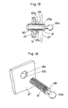
- a screw formation is made on the peripheral surface of the threaded rod 31 to screw it into a screw member 47 described hereinafter.
- the driving-section case is served to guide the movement of the threaded rod 31 in the direction of the rod's axis as shown in Fig. 14,
- numeral 27a designates a through hole through the wall of the driving-section case 27 to insert the rod 31 thereto.
- Numeral 32a designates a ball fixed on the end of the threaded rod 31.
- the threaded rod is allowed to the forward and backward movement without rotation in response to the rotation of the screw member 47 with stability and without any vibration of the mirror 28.
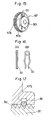
- the screw member 47 has not a female screw but a through hole 50 at the center portion of the screw member 47 for passing the screw member 47. Further the screw member 47 has a boss-like protrusion 47a having a pair of slots 47b in the surface perpendicular to the axis of the screw member 47. More precisely, one of the paired slots 47b is twisted to the other of the paired slots 47b by the angle corresponding to one pitch of the screw of the threaded rod 31. A slightly twisted spring member 51 as shown in Figs. 16 (A) and (B) is inserted into the slots 47b to pinch the threaded rod 31 as shown in Fig. 17 if tge enlarged cross sectional view of the rod 31 and slots 47b.
- the spring member 51 is only allowed to move along the surface perpendicular to the axis of the screw member 47b, and the spring member 51 pinches the valley of the screw of the threaded rod 31, so that the whole of the screw member 47 is served as function of a nut, and further even if overtorque is occurred for moving the threaded rod 31, it is easily absorbed by resilient deformation of the spring member 51 thereby avoiding any damage of the above mechanism.
- a gear at the peripheral surface of the screw member 47 in order to make simple the mechanism 53 in Fig. 8 for transmitting driving force from the motors 52 and 52 to the screw member 47.
- a driving-section case which is the same as that shown in Fig. 7 is shown.
- the waterproof cover is composed of unbrella-like portions 54a and 54a and cover body portion 54b integrally connecting the unbrella-like portions 54a and 54a.
- cover mounting members 55 and 55 surrounding the two threaded rods 31 and 31 and secured to the case 27, and the lower portion of the cover body portion 54b is fitted to the cover mounting members 55.
- a single waterproof cover 54 prevents two threaded rods 31 and 31 from water, and the cover 54 has a simple configuration and mounting of the cover 54 to the rods are very easy.
- FIGs. 21 and 22 there is shown another embodiment of the present invention being mainly different from the above-mentioned embodiment at the follwoing two points.
- One point of the two points is that there is provided no screw hole at the end portion of the Column 44' mounted at the central bottom poriton of the ball base 35 of the pivot connection, and a clip 56 having a plurality of tongue pieces 56a at inner portion'thereof.
- the coil spring 43 inserted into the column 44' is held by the clip 56, namely by biting of the tongue pieces 56a against the free end portion of the column 44'.
- the electric remote control mirror apparatus of the present invention is mainly composed of a pivot connection and a mirror inclining menas; at first, the pivot connection composed of a ball base having a concave surface integrally formed with the member fixed to the mirror housing as a fixed body, a cylindrical hole provided at the centeal portion of the concave surface coaxially with the pivot axis, and elongated projections formed at the inner wall of the cylindrical hole and extending in the direction of the pivot axis; boss portion integrally formed with the mirror body as a movable body, for fitting to the concave surface of the ball base; a presure applying member having a half-ball like portion to be fitted to the inner surface of the boss portions of the mirror body, a cylindrical portion to be inserted into the cylindrical hole, and slots to be connected to the elongated projections; and a coil spring received in the cylindrical portion of the pressure applying member for urging the pressure applying member against the ball base; secondary the mirror inclining means is composed of a threaded
- the rotation of the threaded rod around the pivot axis is avoided, the whole thickness of the mirror apparatus being reduced, the rotating resistance being easily and precisely adjustable, the adjusted condition of the rotating resistance being not changed in use, and vibration and change of inclination of the mirror body being not occurred.
Landscapes
- Engineering & Computer Science (AREA)
- Multimedia (AREA)
- Mechanical Engineering (AREA)
- Rear-View Mirror Devices That Are Mounted On The Exterior Of The Vehicle (AREA)
- Pivots And Pivotal Connections (AREA)
Priority Applications (1)
| Application Number | Priority Date | Filing Date | Title |
|---|---|---|---|
| DE8585110324T DE3278990D1 (en) | 1982-02-08 | 1982-04-23 | Electric remote control mirror apparatus |
Applications Claiming Priority (2)
| Application Number | Priority Date | Filing Date | Title |
|---|---|---|---|
| JP17604/82 | 1982-02-08 | ||
| JP57017604A JPS58136536A (ja) | 1982-02-08 | 1982-02-08 | 電動式リモ−トコントロ−ルミラ− |
Related Child Applications (1)
| Application Number | Title | Priority Date | Filing Date |
|---|---|---|---|
| EP85110324.2 Division-Into | 1985-08-19 |
Publications (3)
| Publication Number | Publication Date |
|---|---|
| EP0085737A2 true EP0085737A2 (fr) | 1983-08-17 |
| EP0085737A3 EP0085737A3 (en) | 1984-05-23 |
| EP0085737B1 EP0085737B1 (fr) | 1986-12-30 |
Family
ID=11948479
Family Applications (2)
| Application Number | Title | Priority Date | Filing Date |
|---|---|---|---|
| EP85110324A Expired EP0170296B1 (fr) | 1982-02-08 | 1982-04-23 | Miroir télécommandé électrique |
| EP82103447A Expired EP0085737B1 (fr) | 1982-02-08 | 1982-04-23 | Dispositif d'un miroir du type à télécommande électrique |
Family Applications Before (1)
| Application Number | Title | Priority Date | Filing Date |
|---|---|---|---|
| EP85110324A Expired EP0170296B1 (fr) | 1982-02-08 | 1982-04-23 | Miroir télécommandé électrique |
Country Status (4)
| Country | Link |
|---|---|
| US (1) | US4555166A (fr) |
| EP (2) | EP0170296B1 (fr) |
| JP (1) | JPS58136536A (fr) |
| DE (1) | DE3274827D1 (fr) |
Cited By (6)
| Publication number | Priority date | Publication date | Assignee | Title |
|---|---|---|---|---|
| FR2558968A1 (fr) * | 1984-01-24 | 1985-08-02 | Matsuyama Seisakusho | Element de support et d'actionnement pour un dispositif a miroir |
| EP0395052A1 (fr) * | 1989-04-26 | 1990-10-31 | Magna Auteca Autozubehörgesellschaft M.B.H. | Rétroviseur réglable pour véhicule automobile |
| US5124846A (en) * | 1989-05-29 | 1992-06-23 | Hohe Kg | Outside rear-view mirror for vehicles |
| FR2755079A1 (fr) * | 1996-10-29 | 1998-04-30 | Buehler Gmbh Nachf Geb | Dispositif d'accouplement pour relier de facon articulee le porte-miroir d'un retroviseur |
| RU2309062C2 (ru) * | 2003-06-16 | 2007-10-27 | Метагал Индустрия Э Комерсио Лтда | Устройство исполнительного механизма |
| CN102416904A (zh) * | 2011-10-10 | 2012-04-18 | 无锡市锡春汽车部件有限公司 | 汽车后视镜防松转动装置 |
Families Citing this family (63)
| Publication number | Priority date | Publication date | Assignee | Title |
|---|---|---|---|---|
| EP0203456B1 (fr) * | 1985-05-14 | 1990-03-28 | Ichikoh Industries Limited | Dispositif de commande électrique d'un miroir |
| US4764004A (en) * | 1986-08-04 | 1988-08-16 | Kabushiki Kaisha Tokai Rika Denki Seisakusho | Automobile outer mirror assembly |
| JPH05444Y2 (fr) * | 1986-11-26 | 1993-01-07 | ||
| JPH0628358Y2 (ja) * | 1988-04-11 | 1994-08-03 | 株式会社村上開明堂 | バックミラー |
| JPH0535877Y2 (fr) * | 1988-08-19 | 1993-09-10 | ||
| US4915493A (en) * | 1989-01-04 | 1990-04-10 | Magna International Inc. | Automotive rear view mirror assembly |
| US5313336A (en) * | 1989-02-15 | 1994-05-17 | Kabushiki Kaisha Matsuyama Seisakusho | Rearview mirror assembly for motor vehicle |
| JPH02117236U (fr) * | 1989-03-08 | 1990-09-19 | ||
| EP0485620B1 (fr) * | 1990-05-29 | 1995-10-11 | Ichikoh Industries Limited | Retroviseur a telecommande electrique |
| US5226034A (en) * | 1990-06-19 | 1993-07-06 | Ichikoh Industries, Ltd. | Electrically remote-controlled type mirror assembly |
| JPH0550881A (ja) * | 1991-08-19 | 1993-03-02 | Ichikoh Ind Ltd | 電動式リモートコントロールミラーおよびその制御回路 |
| FR2704816B1 (fr) * | 1993-05-07 | 1995-08-04 | Harman Automotive Sa | Mecanisme de reglage de position d'un miroir de retroviseur exterieur. |
| US5363246A (en) | 1993-05-12 | 1994-11-08 | United Technologies Automotive, Inc. | Power pack for an automotive exterior mirror assembly |
| AU676322B2 (en) * | 1993-05-12 | 1997-03-06 | United Technologies Automotive, Inc. | Mirror assembly for the exterior of an automotive vehicle having a hand set adjustment mechanism |
| US5487522A (en) * | 1993-11-30 | 1996-01-30 | Donnelly Corporation | Mirror support bracket |
| NL9401791A (nl) * | 1994-10-27 | 1996-06-03 | Iku Holding Montfoort Bv | Verplaatsingsinstelinrichting. |
| US5701211A (en) * | 1995-03-31 | 1997-12-23 | United Technologies Automotive Systems, Inc. | Vehicle mirror adjustment gear train |
| US5721646A (en) * | 1996-02-23 | 1998-02-24 | Kam Truck Components, Inc. | Exterior rearview mirror for vehicles |
| DE19609017A1 (de) * | 1996-03-08 | 1997-09-11 | Reitter & Schefenacker Gmbh | Außenrückblickspiegel für Fahrzeuge, vorzugsweise für Kraftfahrzeuge |
| US5946151A (en) * | 1997-03-17 | 1999-08-31 | Siegel-Robert, Inc. | Automobile pivotal mirror mounting assembly |
| NL1007676C2 (nl) * | 1997-12-02 | 1999-06-03 | Iku Holding Montfoort Bv | Werkwijze voor het monteren van verstelmiddelen voor een spiegelend element in een binnen- of buitenspiegel voor een motorvoertuig, hiervoor gebruikte montageplaat en spiegel voorzien van een dergelijke montageplaat. |
| US6168279B1 (en) | 1998-03-25 | 2001-01-02 | Donnelly Corporation | Pivot support for adjustable rearview mirror |
| DE19840004A1 (de) * | 1998-09-02 | 2000-03-09 | Mekra Lang Gmbh & Co Kg | Außenspiegel für Kraftfahrzeuge |
| DE19904778C2 (de) | 1999-02-05 | 2001-04-12 | Mekra Lang Gmbh & Co Kg | System zur automatischen Aussenspiegelverstellung bei Kurvenfahrten von Fahrzeugen |
| DE19913072B4 (de) | 1999-03-23 | 2005-10-13 | Mekra Lang Gmbh & Co. Kg | Außenspiegel für Kraftfahrzeuge |
| US6234757B1 (en) | 1999-06-15 | 2001-05-22 | Hunter Fan Company | System for suspending a ceiling fan |
| US6139279A (en) * | 1999-06-15 | 2000-10-31 | Hunter Fan Company | System for suspending a ceiling fan |
| US6491402B1 (en) | 1999-09-07 | 2002-12-10 | Lang-Mekra North America, Llc | Mirror mounting assembly with modular components |
| US6302549B1 (en) | 1999-09-07 | 2001-10-16 | Lang-Mekra North America, Llc | Mirror mounting assembly with biaxial adjustability |
| US6672730B1 (en) | 1999-09-15 | 2004-01-06 | Hadley Products | Vehicular exterior rearview mirror assembly with actuator |
| US6325520B1 (en) | 1999-09-15 | 2001-12-04 | Kam Truck Components, Inc. | Vehicular exterior rearview mirror assembly with actuator |
| AUPQ283499A0 (en) * | 1999-09-15 | 1999-10-07 | Britax Rainsfords Pty Ltd | A mirror mounting assembly for controlling vibration of a mirror |
| US6522451B1 (en) * | 2000-01-06 | 2003-02-18 | Donnelly Corporation | Exterior mirror plano-auxiliary reflective element assembly |
| US6717712B2 (en) * | 2000-01-06 | 2004-04-06 | Donnelly Corporation | Exterior mirror plano-auxiliary reflective element assembly |
| US7198924B2 (en) | 2000-12-11 | 2007-04-03 | Invitrogen Corporation | Methods and compositions for synthesis of nucleic acid molecules using multiple recognition sites |
| DE20105791U1 (de) | 2001-04-03 | 2002-08-14 | MEKRA Lang GmbH & Co. KG, 90765 Fürth | Spiegelanordnung für Kraftfahrzeuge |
| DE20106977U1 (de) | 2001-04-23 | 2002-08-29 | Mekra Lang Gmbh & Co Kg | Warneinrichtung in Kraftfahrzeugen |
| US6916100B2 (en) * | 2001-06-27 | 2005-07-12 | Donnelly Corporation | Vehicle exterior rearview mirror assembly |
| AUPR683201A0 (en) * | 2001-08-06 | 2001-08-30 | Schefenacker Vision Systems Australia Pty Ltd | Hand adjustable vechicle mirror mechanism |
| DE10148611B4 (de) | 2001-10-02 | 2005-01-27 | Mekra Lang Gmbh & Co. Kg | Vorrichtung zum schwenkbeweglichen Lagern eines Tragarms für einen Aussenspiegel |
| NL1019524C2 (nl) * | 2001-12-07 | 2003-06-11 | Iku Holding Montfoort Bv | Spiegelverstelmechanisme met elektrische verbinding. |
| US6793357B2 (en) | 2001-12-26 | 2004-09-21 | Lang Mekra North America, Llc | Vehicle mirror mounting apparatus and method for assembling same |
| US7420756B2 (en) | 2003-05-20 | 2008-09-02 | Donnelly Corporation | Mirror reflective element |
| US7249744B2 (en) * | 2003-10-09 | 2007-07-31 | Hunter Fan Company | Quick connect mounting system for a ceiling fan |
| US8304189B2 (en) | 2003-12-01 | 2012-11-06 | Life Technologies Corporation | Nucleic acid molecules containing recombination sites and methods of using the same |
| NL1025884C2 (nl) * | 2004-04-05 | 2005-10-07 | Iku Holding Montfoort Bv | Gebruik van een metaalzout van een vetzuur voor het dempen van trillingen, werkwijze voor het samenstellen van een spiegelverstelmechanisme, spiegelverstelmechanisme. |
| ATE517368T1 (de) | 2005-05-16 | 2011-08-15 | Donnelly Corp | Fahrzeugspiegelanordnung mit zeichen am reflektierenden teil |
| US11242009B2 (en) | 2005-07-06 | 2022-02-08 | Donnelly Corporation | Vehicular exterior mirror system with blind spot indicator |
| US11498487B2 (en) | 2005-07-06 | 2022-11-15 | Magna Mirrors Of America, Inc. | Vehicular exterior mirror system with blind spot indicator |
| WO2008051910A2 (fr) | 2006-10-24 | 2008-05-02 | Donnelly Corporation | Dispositif d'affichage pour un rétroviseur |
| US7944371B2 (en) | 2007-11-05 | 2011-05-17 | Magna Mirrors Of America, Inc. | Exterior mirror with indicator |
| US11890991B2 (en) | 2006-10-24 | 2024-02-06 | Magna Mirrors Of America, Inc. | Vehicular exterior rearview mirror assembly with blind spot indicator element |
| US7748856B2 (en) | 2007-05-23 | 2010-07-06 | Donnelly Corporation | Exterior mirror element with integral wide angle portion |
| US8736940B2 (en) | 2011-09-30 | 2014-05-27 | Magna Mirrors Of America, Inc. | Exterior mirror with integral spotter mirror and method of making same |
| US8801245B2 (en) | 2011-11-14 | 2014-08-12 | Magna Mirrors Of America, Inc. | Illumination module for vehicle |
| CN102514529B (zh) * | 2011-12-29 | 2015-01-07 | 北京光华荣昌汽车部件有限公司 | 一种模块化设计的汽车后视镜倾角调节装置 |
| WO2014046334A1 (fr) * | 2012-09-24 | 2014-03-27 | (주)오앤케이테크 | Pignon entraîneur et actionneur de rétroviseur |
| KR200469818Y1 (ko) * | 2012-09-24 | 2013-11-12 | (주)오앤케이테크 | 미러 액추에이터 |
| US9216691B2 (en) | 2013-02-25 | 2015-12-22 | Magna Mirrors Of America, Inc. | Exterior mirror with spotter mirror |
| JP2015202800A (ja) * | 2014-04-15 | 2015-11-16 | サカエ理研工業株式会社 | 鏡面角度調整装置 |
| US9761144B2 (en) | 2014-09-11 | 2017-09-12 | Magna Mirrors Of America, Inc. | Exterior mirror with blind zone indicator |
| NL2013771B1 (nl) * | 2014-11-11 | 2016-10-06 | MCI (Mirror Controls International) Netherlands B V | Inrichting voor het verstellen van een schaalvormig behuizingsdeel, een draagframe voor gebruik in een dergelijke inrichting, en een voertuig voorzien van een dergelijke inrichting. |
| DE202019100579U1 (de) * | 2019-01-31 | 2019-02-25 | Mci (Mirror Controls International) Netherlands B.V. | Sichteinstellmechanismus |
Family Cites Families (12)
| Publication number | Priority date | Publication date | Assignee | Title |
|---|---|---|---|---|
| US3609014A (en) * | 1970-06-10 | 1971-09-28 | Kurz Arthur W Jun | Electric remote control rear view mirror |
| CA1081013A (fr) * | 1975-07-09 | 1980-07-08 | Harman International Industries | Retroviseur reglable par telecommande |
| US4076392A (en) * | 1975-11-26 | 1978-02-28 | Murakami Kaimedio Co., Ltd. | Remotely controllable rear view mirror |
| US4202603A (en) * | 1977-05-31 | 1980-05-13 | Koito Manufacturing Company Limited | Remotely controlled mirrors |
| DE2937961C2 (de) * | 1978-09-27 | 1983-07-21 | Murakami Kaimeido Co., Ltd., Shizuoka | Vorrichtung zum Verstellen eines Spiegelglasträgers eines Kraftfahrzeugrückspiegels |
| US4362362A (en) * | 1979-10-17 | 1982-12-07 | Kabushiki Kaisha Tokai Rika Denki Seisakusho | Electric remote control rearview mirror |
| DE3010308A1 (de) * | 1980-03-18 | 1981-10-01 | SWF-Spezialfabrik für Autozubehör Gustav Rau GmbH, 7120 Bietigheim-Bissingen | Einrichtung zur verstellung eines beweglich gelagerten elementes |
| FR2486885A2 (fr) * | 1980-07-18 | 1982-01-22 | Manzoni Stephane | Dispositif de commande d'un miroir de retroviseur pour vehicule |
| FR2501599A1 (fr) * | 1981-03-10 | 1982-09-17 | Manzoni Bouchot Sa | Dispositif de montage d'un boitier de retroviseur sur un organe de support |
| US4494420A (en) * | 1981-05-08 | 1985-01-22 | Koito Seisakusho Co., Ltd. | Rotary-to-linear converter mechanism for a remotely controlled rearview mirror tilting device or the like |
| JPS5854347U (ja) * | 1981-10-09 | 1983-04-13 | 市光工業株式会社 | 電動式リモ−トコントロ−ルミラ− |
| DE3148525A1 (de) * | 1981-12-08 | 1983-06-16 | Harman International Industries GmbH, 7100 Heilbronn | Verstellbarer aussenspiegel |
-
1982
- 1982-02-08 JP JP57017604A patent/JPS58136536A/ja active Granted
- 1982-04-23 EP EP85110324A patent/EP0170296B1/fr not_active Expired
- 1982-04-23 DE DE8282103447T patent/DE3274827D1/de not_active Expired
- 1982-04-23 EP EP82103447A patent/EP0085737B1/fr not_active Expired
- 1982-04-30 US US06/373,783 patent/US4555166A/en not_active Expired - Lifetime
Cited By (8)
| Publication number | Priority date | Publication date | Assignee | Title |
|---|---|---|---|---|
| FR2558968A1 (fr) * | 1984-01-24 | 1985-08-02 | Matsuyama Seisakusho | Element de support et d'actionnement pour un dispositif a miroir |
| EP0395052A1 (fr) * | 1989-04-26 | 1990-10-31 | Magna Auteca Autozubehörgesellschaft M.B.H. | Rétroviseur réglable pour véhicule automobile |
| US5124846A (en) * | 1989-05-29 | 1992-06-23 | Hohe Kg | Outside rear-view mirror for vehicles |
| FR2755079A1 (fr) * | 1996-10-29 | 1998-04-30 | Buehler Gmbh Nachf Geb | Dispositif d'accouplement pour relier de facon articulee le porte-miroir d'un retroviseur |
| WO1998018653A1 (fr) * | 1996-10-29 | 1998-05-07 | Gebr. Bühler Nachfolger Gmbh | Dispositif d'accouplement pour relier de maniere articulee le support de la glace du retroviseur d'un vehicule a moteur au boitier du mecanisme d'entrainement du retroviseur |
| RU2309062C2 (ru) * | 2003-06-16 | 2007-10-27 | Метагал Индустрия Э Комерсио Лтда | Устройство исполнительного механизма |
| CN102416904A (zh) * | 2011-10-10 | 2012-04-18 | 无锡市锡春汽车部件有限公司 | 汽车后视镜防松转动装置 |
| CN102416904B (zh) * | 2011-10-10 | 2016-07-06 | 无锡市锡春汽车部件有限公司 | 汽车后视镜防松转动装置 |
Also Published As
| Publication number | Publication date |
|---|---|
| EP0085737A3 (en) | 1984-05-23 |
| JPS6348733B2 (fr) | 1988-09-30 |
| US4555166A (en) | 1985-11-26 |
| EP0170296B1 (fr) | 1988-09-07 |
| JPS58136536A (ja) | 1983-08-13 |
| EP0085737B1 (fr) | 1986-12-30 |
| EP0170296A1 (fr) | 1986-02-05 |
| DE3274827D1 (en) | 1987-02-05 |
Similar Documents
| Publication | Publication Date | Title |
|---|---|---|
| EP0085737B1 (fr) | Dispositif d'un miroir du type à télécommande électrique | |
| EP0511203B1 (fr) | Ensemble de retroviseur pour automobiles | |
| KR100425075B1 (ko) | 단일피벗형전동접힘식백미러 | |
| EP0321716B1 (fr) | Dispositif d'entraînement pour rétroviseur commandé à distance électriquement | |
| KR100345360B1 (ko) | 미러의 개선된 2중 피벗부재의 장착 | |
| JPH055822Y2 (fr) | ||
| US5087098A (en) | Lumbar support device | |
| KR100377435B1 (ko) | 차량용 스티어링 컬럼의 위치조절장치 | |
| KR20030047881A (ko) | 모터 차량용 조절 가능한 페달 기구 | |
| GB2032367A (en) | Electric mirror angle adjusting device | |
| US4279473A (en) | Remote control mechanism | |
| US4896918A (en) | Lumbar support regulating apparatus | |
| ES8403069A1 (es) | Mecanismo con limitador de para para el accionamiento de un espejo retrovisor para vehiculos. | |
| JP2768378B2 (ja) | 分離型バック・ミラー・アッセンブリー | |
| US5623374A (en) | Spring detent for foldable side mount rear view mirror | |
| US6270227B1 (en) | Remote-controlled mirror apparatus for vehicles | |
| US4988068A (en) | Remote control mechanism | |
| US4824232A (en) | Drive system with resilient yieldable biased actuator shaft for electric rear view mirror | |
| US5301568A (en) | Stick lever device | |
| EP0269081B1 (fr) | Dispositif de support pour un élément de miroir de rétroviseur | |
| US6079287A (en) | Locking device | |
| US4250767A (en) | Remotely controlled rearview mirror assembly | |
| US4790199A (en) | Mechanical control device | |
| CA1212564A (fr) | Mecanisme a engrenage pour telecommande regulatrice de retroviseur lateral | |
| EP1129905B1 (fr) | Rétroviseur extérieur |
Legal Events
| Date | Code | Title | Description |
|---|---|---|---|
| PUAI | Public reference made under article 153(3) epc to a published international application that has entered the european phase |
Free format text: ORIGINAL CODE: 0009012 |
|
| AK | Designated contracting states |
Designated state(s): DE FR GB |
|
| PUAL | Search report despatched |
Free format text: ORIGINAL CODE: 0009013 |
|
| AK | Designated contracting states |
Designated state(s): DE FR GB |
|
| 17P | Request for examination filed |
Effective date: 19840508 |
|
| GRAA | (expected) grant |
Free format text: ORIGINAL CODE: 0009210 |
|
| AK | Designated contracting states |
Kind code of ref document: B1 Designated state(s): DE FR GB |
|
| REF | Corresponds to: |
Ref document number: 3274827 Country of ref document: DE Date of ref document: 19870205 |
|
| ET | Fr: translation filed | ||
| PLBE | No opposition filed within time limit |
Free format text: ORIGINAL CODE: 0009261 |
|
| STAA | Information on the status of an ep patent application or granted ep patent |
Free format text: STATUS: NO OPPOSITION FILED WITHIN TIME LIMIT |
|
| 26N | No opposition filed | ||
| PGFP | Annual fee paid to national office [announced via postgrant information from national office to epo] |
Ref country code: GB Payment date: 19950410 Year of fee payment: 14 |
|
| PGFP | Annual fee paid to national office [announced via postgrant information from national office to epo] |
Ref country code: FR Payment date: 19950419 Year of fee payment: 14 |
|
| PGFP | Annual fee paid to national office [announced via postgrant information from national office to epo] |
Ref country code: DE Payment date: 19950425 Year of fee payment: 14 |
|
| PG25 | Lapsed in a contracting state [announced via postgrant information from national office to epo] |
Ref country code: GB Effective date: 19960423 |
|
| GBPC | Gb: european patent ceased through non-payment of renewal fee |
Effective date: 19960423 |
|
| PG25 | Lapsed in a contracting state [announced via postgrant information from national office to epo] |
Ref country code: FR Effective date: 19961227 |
|
| PG25 | Lapsed in a contracting state [announced via postgrant information from national office to epo] |
Ref country code: DE Effective date: 19970101 |
|
| REG | Reference to a national code |
Ref country code: FR Ref legal event code: ST |