EP0085846A1 - Dispositif de collection d'énergie solaire - Google Patents
Dispositif de collection d'énergie solaire Download PDFInfo
- Publication number
- EP0085846A1 EP0085846A1 EP83100301A EP83100301A EP0085846A1 EP 0085846 A1 EP0085846 A1 EP 0085846A1 EP 83100301 A EP83100301 A EP 83100301A EP 83100301 A EP83100301 A EP 83100301A EP 0085846 A1 EP0085846 A1 EP 0085846A1
- Authority
- EP
- European Patent Office
- Prior art keywords
- capsule
- solar
- light receiving
- receiving surface
- transparent members
- Prior art date
- Legal status (The legal status is an assumption and is not a legal conclusion. Google has not performed a legal analysis and makes no representation as to the accuracy of the status listed.)
- Granted
Links
- 239000002775 capsule Substances 0.000 claims abstract description 50
- 230000002093 peripheral effect Effects 0.000 claims description 5
- 230000000694 effects Effects 0.000 abstract description 2
- 238000010276 construction Methods 0.000 description 2
- 239000000428 dust Substances 0.000 description 2
- 238000009434 installation Methods 0.000 description 1
- 238000012986 modification Methods 0.000 description 1
- 230000004048 modification Effects 0.000 description 1
- 230000003287 optical effect Effects 0.000 description 1
- 230000035515 penetration Effects 0.000 description 1
- 239000012780 transparent material Substances 0.000 description 1
Images



Classifications
-
- F—MECHANICAL ENGINEERING; LIGHTING; HEATING; WEAPONS; BLASTING
- F24—HEATING; RANGES; VENTILATING
- F24S—SOLAR HEAT COLLECTORS; SOLAR HEAT SYSTEMS
- F24S23/00—Arrangements for concentrating solar-rays for solar heat collectors
- F24S23/30—Arrangements for concentrating solar-rays for solar heat collectors with lenses
-
- F—MECHANICAL ENGINEERING; LIGHTING; HEATING; WEAPONS; BLASTING
- F24—HEATING; RANGES; VENTILATING
- F24S—SOLAR HEAT COLLECTORS; SOLAR HEAT SYSTEMS
- F24S30/00—Arrangements for moving or orienting solar heat collector modules
- F24S30/40—Arrangements for moving or orienting solar heat collector modules for rotary movement
- F24S30/45—Arrangements for moving or orienting solar heat collector modules for rotary movement with two rotation axes
- F24S30/452—Vertical primary axis
-
- F—MECHANICAL ENGINEERING; LIGHTING; HEATING; WEAPONS; BLASTING
- F24—HEATING; RANGES; VENTILATING
- F24S—SOLAR HEAT COLLECTORS; SOLAR HEAT SYSTEMS
- F24S50/00—Arrangements for controlling solar heat collectors
- F24S50/20—Arrangements for controlling solar heat collectors for tracking
-
- F—MECHANICAL ENGINEERING; LIGHTING; HEATING; WEAPONS; BLASTING
- F24—HEATING; RANGES; VENTILATING
- F24S—SOLAR HEAT COLLECTORS; SOLAR HEAT SYSTEMS
- F24S80/00—Details, accessories or component parts of solar heat collectors not provided for in groups F24S10/00-F24S70/00
- F24S80/50—Elements for transmitting incoming solar rays and preventing outgoing heat radiation; Transparent coverings
-
- F—MECHANICAL ENGINEERING; LIGHTING; HEATING; WEAPONS; BLASTING
- F24—HEATING; RANGES; VENTILATING
- F24S—SOLAR HEAT COLLECTORS; SOLAR HEAT SYSTEMS
- F24S80/00—Details, accessories or component parts of solar heat collectors not provided for in groups F24S10/00-F24S70/00
- F24S80/50—Elements for transmitting incoming solar rays and preventing outgoing heat radiation; Transparent coverings
- F24S2080/501—Special shape
-
- F—MECHANICAL ENGINEERING; LIGHTING; HEATING; WEAPONS; BLASTING
- F24—HEATING; RANGES; VENTILATING
- F24S—SOLAR HEAT COLLECTORS; SOLAR HEAT SYSTEMS
- F24S25/00—Arrangement of stationary mountings or supports for solar heat collector modules
- F24S25/10—Arrangement of stationary mountings or supports for solar heat collector modules extending in directions away from a supporting surface
-
- Y—GENERAL TAGGING OF NEW TECHNOLOGICAL DEVELOPMENTS; GENERAL TAGGING OF CROSS-SECTIONAL TECHNOLOGIES SPANNING OVER SEVERAL SECTIONS OF THE IPC; TECHNICAL SUBJECTS COVERED BY FORMER USPC CROSS-REFERENCE ART COLLECTIONS [XRACs] AND DIGESTS
- Y02—TECHNOLOGIES OR APPLICATIONS FOR MITIGATION OR ADAPTATION AGAINST CLIMATE CHANGE
- Y02E—REDUCTION OF GREENHOUSE GAS [GHG] EMISSIONS, RELATED TO ENERGY GENERATION, TRANSMISSION OR DISTRIBUTION
- Y02E10/00—Energy generation through renewable energy sources
- Y02E10/40—Solar thermal energy, e.g. solar towers
- Y02E10/47—Mountings or tracking
-
- Y—GENERAL TAGGING OF NEW TECHNOLOGICAL DEVELOPMENTS; GENERAL TAGGING OF CROSS-SECTIONAL TECHNOLOGIES SPANNING OVER SEVERAL SECTIONS OF THE IPC; TECHNICAL SUBJECTS COVERED BY FORMER USPC CROSS-REFERENCE ART COLLECTIONS [XRACs] AND DIGESTS
- Y10—TECHNICAL SUBJECTS COVERED BY FORMER USPC
- Y10S—TECHNICAL SUBJECTS COVERED BY FORMER USPC CROSS-REFERENCE ART COLLECTIONS [XRACs] AND DIGESTS
- Y10S52/00—Static structures, e.g. buildings
- Y10S52/10—Polyhedron
Definitions
- the present invention relates to an apparatus for collecting solar rays and converting their energy into thermal or electric energy and, more particularly, to a solar energy collection apparatus which includes a transparent capsule for protecting its solar ray collector from wind, rain, dust and other undesirable surroundings.
- a solar energy collection apparatus has to be positively proofed against various undesirable surroundings such as wind, rain and dust. This demand is usually satisfied by housing a solar ray collector of the apparatus in a generally spherical unitary body or capsule made of transparent material.
- a problem emerges here is that, when the solar ray collector is bulky, the capsule for accommodating the solar ray collector becomes large-sized and it is quite difficult to form such a large transparent unitary capsule.
- a large-sized capsule may be formed by combining a number of transparent flat plates at random. This has still sufferd from the drawback that the solar ray collection efficiency achievable with a solar ray collector housed in such a capsule is quite limited.
- a solar energy collection apparatus embodying the present invention comprises a housing or capsule made up of a number of interconnected transparent members.
- Solar ray collector means is installed within the capsule and includes a plurality of lenses. These lenses define a light receiving surface the peripheral edge of which contacts imaginary lines which define the range in which the solar rays are allowed to penetrate the capsule. With this construction, the solar rays are collected most effectively for a predetermined size of the capsule by the solar ray collector means.
- a solar ray collection apparatus includes a capsule and a solar ray collector housed in the capsule.
- the solar ray collector is controlled to chase the sun in response to an output of a photodetector which may be located inside or outside the capsule.
- the capsule comprises a number of interconnected transparent members which are inclined by a specific angle which effects the most efficient collection of the solar energy at any position of the sun.
- the apparatus is excellent in mechanical strength and resistivity to wind due to unique configuration of each transparent member.
- a solar energy collection apparatus of the present invention is shown and generally designated by the reference numeral 10.
- the apparatus 10 comprises a generally spherical transparent housing or capsule 12 and a solar ray collector 14 installed in the capsule 12.
- the solar ray collector 14 includes a number of, such as nineteen, lenses 16 adapted to converge the solar rays into photothermal or photoelectric converters (not shown) which are respectively located at the focal points of the lenses 16.
- a photodetector 18 is positioned at the center of a generally circular light receiving surface 20 which is defined by the lenses 16.
- the lenses 16 and photodetector 18 are integrally bundled up by a support frame or lens frame 22.
- a first drive unit such as a motor 24 drives the lens assembly in a direction indicated by an arrow A in Fi g . 2.
- the lens assembly and motor 24 are integrally supported by a generally C-shaped arm 26 which is rigidly mounted on a rotary shaft 28. This shaft 28 extends perpendicular to the axis of rotation of the motor 24 and is driven in a direction indicated by an arrow B by a second drive unit such as a motor (not shown).
- the photodetector 18 senses a position of the sun at any time.
- the first and second motors are controlled in response to an output of the photodetector 18 such that the light receiving surface 20 of the lens assembly 16 constantly chases the sun.
- optical cables may be so located as to receive the converged sunlight at the focal points of the respective lenses 16 and transmit it to any desired location for a desired application.
- the capsule 12 comprises a generally cylindrical base section 30 and a generally spherical or dome-shaped section 32 which emerges from the top of the base section 30.
- the dome 32 is made up of a plurality of interconnected pentagonal and hexagonal transparent plates 34 1 , 34 2 ... 34 m .
- the solar ray collector 14 is controlled to constantly face the sun at the light receiving surface 20 thereof, as previously described. Hence, when the solar rays are incident on the capsule 12 in the direction L as shown in Fig. 3, the incidence angle 8 2 on the plate 34 2 , for example, is so large that the sunlight is not introduced into the capsule 12 but totally reflected by the plate 34 2 .
- the incidence angle 6 3 on the adjacent plate 34 2 is smaller than the incidence angle ⁇ 3 and the incidence angle 8 4 is even smaller than the incidence angle 6 3 . Therefore, at a certain incidence angle smaller than ⁇ 2 . the sunlight is allowed to penetrate the capsule 12. It follows that the installation of the solar ray collector 14 will be most effective when its diameter D is so designed as to locate the peripheral edge 36 of the light receiving surface 20 at the position which the light of the specific incidence angle smaller than ⁇ 2 reaches.
- the most effective design of the capsule 12 will be such that supposing lines & which extend from the peripheral edge 36 perpendicularly to the light receiving surface 20, the plates 34 5 and 34 8 intersecting the lines l are inclined by angles ⁇ 5 and ⁇ 8 which have the maximum value within the allowable range for the penetration of the solar rays into the capsule 12.
- the solar ray collector 14 inside the capsule 12 can collect the solar rays or energy in its most efficient manner.
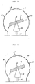
- FIG. 4 another embodiment of the present invention is shown which is essentially similar to the first embodiment but different in the profile of the transparent plates of the capsule 12.
- the plates 38 shown in Fig. 4 are individually formed slightly convex toward the outside. It will be seen that such a shape of the transparent plates 38 increases the mechanical strength of the capsule 12 and, therefore, permits the plates 38 to be formed thinner than the plates 34.
- the capsule 12 may be made up of transparent plates shown in Fig. 5 which are individually formed somewhat concave toward the outside. The capsule shown in Fig. 5 will prove particularly resistant to wind.
- the transparent plates may have any other suitable configuration in principle, such as triangle, circle, quadrangle, pentagon, hexagon, trapezoid and banana-shape or a combination thereof. Still, the combined pentagonal and hexagonal plates can be effectively interconnected without any gap to enhance the resistivity of the resulting capsule 12 to wind.
- FIG. 6 another embodiment of the present invention is shown which is similar to the construction shown in Fig. 2 but features a unique lens arrangement.
- the lenses 16 shown in Fig. 6 the lenses 16' intersecting the axis of rotation of the motor 24 have a profile which resembles a convex lens. With this arrangement, the focal point of each lens 16 1 is prevented from intersecting the axis of rotation of the motor 24.
- FIG. 7 still another embodiment of the present invention is shown which includes a plurality of photodetectors 18. While the single photodetector 18 in the foregoing embodiments will fail to properly operate when the joint between adjacent transparent plates of the capsule 12 becomes located just there- above, either one of the photosensors 18 shown in Fig. 7 will always and accurately sense the sun even when the other fails in the situation mentioned above.
- the present invention provides a large-sized solar energy collection apparatus which efficiently collects the solar energy despite the use of a capsule which is formed by numerous plates. Additionally a capsule of the apparatus is resistive to wind and excellent in mechanical strength
- the entire light receiving surface 20 of the lens assembly may be provided with a generally hemispherical configuration.
- the photodetector 18 may be replaced by a sun chasing unit located outside the capsule 12 and constructed to drive the solar ray collector 14 with its output.
Landscapes
- Engineering & Computer Science (AREA)
- Chemical & Material Sciences (AREA)
- Life Sciences & Earth Sciences (AREA)
- Sustainable Development (AREA)
- Sustainable Energy (AREA)
- Thermal Sciences (AREA)
- Physics & Mathematics (AREA)
- Combustion & Propulsion (AREA)
- Mechanical Engineering (AREA)
- General Engineering & Computer Science (AREA)
- Photovoltaic Devices (AREA)
- Photometry And Measurement Of Optical Pulse Characteristics (AREA)
- Mounting And Adjusting Of Optical Elements (AREA)
Applications Claiming Priority (2)
| Application Number | Priority Date | Filing Date | Title |
|---|---|---|---|
| JP57010680A JPS6019413B2 (ja) | 1982-01-26 | 1982-01-26 | 太陽光収集装置 |
| JP10680/82 | 1982-01-26 |
Publications (2)
| Publication Number | Publication Date |
|---|---|
| EP0085846A1 true EP0085846A1 (fr) | 1983-08-17 |
| EP0085846B1 EP0085846B1 (fr) | 1988-04-06 |
Family
ID=11756970
Family Applications (1)
| Application Number | Title | Priority Date | Filing Date |
|---|---|---|---|
| EP83100301A Expired EP0085846B1 (fr) | 1982-01-26 | 1983-01-14 | Dispositif de collection d'énergie solaire |
Country Status (9)
| Country | Link |
|---|---|
| US (1) | US4509500A (fr) |
| EP (1) | EP0085846B1 (fr) |
| JP (1) | JPS6019413B2 (fr) |
| KR (1) | KR840002093A (fr) |
| AU (1) | AU537175B2 (fr) |
| CA (1) | CA1239066A (fr) |
| DE (1) | DE3376231D1 (fr) |
| HK (1) | HK94888A (fr) |
| NZ (1) | NZ203040A (fr) |
Cited By (2)
| Publication number | Priority date | Publication date | Assignee | Title |
|---|---|---|---|---|
| US6067982A (en) * | 1995-12-29 | 2000-05-30 | Harrison; John | Collection of solar radiation and its conversion into electrical power |
| GB2484353A (en) * | 2010-09-06 | 2012-04-11 | Michael Harris | Solar oven |
Families Citing this family (11)
| Publication number | Priority date | Publication date | Assignee | Title |
|---|---|---|---|---|
| JPH01289006A (ja) * | 1988-05-17 | 1989-11-21 | Takashi Mori | 太陽光収集装置 |
| DE4219909C2 (de) * | 1992-06-17 | 1995-02-09 | Friedrich Mueller | Sonnenkollektor |
| US5427628A (en) * | 1992-06-22 | 1995-06-27 | Hartley; Douglas J. | Solar rhyno |
| US20090038607A1 (en) * | 2006-01-04 | 2009-02-12 | Wayne Staney | Motorized tracking device |
| JP4943713B2 (ja) * | 2006-02-21 | 2012-05-30 | 株式会社バルダン | ボビン保持具 |
| US20080066737A1 (en) * | 2006-09-06 | 2008-03-20 | Harris Corporation | Solar energy collection system for use in generating electric power from solar energy |
| US20080115817A1 (en) * | 2006-11-21 | 2008-05-22 | Defries Anthony | Combined Energy Conversion |
| TWM341193U (en) * | 2008-02-05 | 2008-09-21 | Tennrich Int Corp | Display apparatus for displaying light intensity and its application |
| US8539735B2 (en) * | 2008-06-25 | 2013-09-24 | Jeffrey Max Belicofski | Method of construction using a Geodesic honeycomb skeleton |
| US20100095605A1 (en) * | 2008-06-25 | 2010-04-22 | Jeffrey Max Belicofski | Novel method of construction using a geodesic honeycomb skeleton |
| KR102600555B1 (ko) * | 2022-11-30 | 2023-11-09 | 이찬영 | 수직면의 출입구를 갖는 지오데식 돔형 구조물 |
Citations (2)
| Publication number | Priority date | Publication date | Assignee | Title |
|---|---|---|---|---|
| DE2830516A1 (de) * | 1978-07-12 | 1980-01-24 | Messerschmitt Boelkow Blohm | Selbsttragende abdeckung von antennen |
| EP0043082A2 (fr) * | 1980-06-27 | 1982-01-06 | Kei Mori | Collecteur d'énergie solaire optique |
Family Cites Families (11)
| Publication number | Priority date | Publication date | Assignee | Title |
|---|---|---|---|---|
| US3493291A (en) * | 1966-06-22 | 1970-02-03 | James E Webb | High temperature lens construction |
| US3934573A (en) * | 1975-02-28 | 1976-01-27 | Dandini Alessandro O | Spherical system for the concentration and extraction of solar energy |
| US3998204A (en) * | 1975-05-13 | 1976-12-21 | Fuchs Francis J | Floatable ball |
| US4223174A (en) * | 1976-07-19 | 1980-09-16 | Sun Trac Corporation | Sun-tracking solar energy conversion system |
| US4136670A (en) * | 1977-06-13 | 1979-01-30 | Davis Theodore L | Solar heating collector apparatus |
| US4229941A (en) * | 1978-01-25 | 1980-10-28 | Solwin Industries, Inc. | Method of and system for generating energy from solar and wind energy sources |
| US4187832A (en) * | 1978-06-07 | 1980-02-12 | Tregoning Robert H | Cosmic and solar ray hot water heater |
| US4267826A (en) * | 1978-06-20 | 1981-05-19 | Dale C. Miller | Solar collector for heating and cooling |
| US4341203A (en) * | 1978-10-30 | 1982-07-27 | Bloxsom Dan E | Solar energy collector |
| US4299201A (en) * | 1979-06-19 | 1981-11-10 | Junjiro Tsubota | Solar energy focusing means |
| JPS5719549A (en) * | 1980-07-08 | 1982-02-01 | Takashi Henmi | Solar furnace |
-
1982
- 1982-01-26 JP JP57010680A patent/JPS6019413B2/ja not_active Expired
- 1982-10-28 KR KR1019820004858A patent/KR840002093A/ko not_active Withdrawn
-
1983
- 1983-01-14 EP EP83100301A patent/EP0085846B1/fr not_active Expired
- 1983-01-14 DE DE8383100301T patent/DE3376231D1/de not_active Expired
- 1983-01-17 NZ NZ203040A patent/NZ203040A/en unknown
- 1983-01-19 US US06/459,087 patent/US4509500A/en not_active Expired - Fee Related
- 1983-01-19 AU AU10597/83A patent/AU537175B2/en not_active Ceased
- 1983-01-25 CA CA000420170A patent/CA1239066A/fr not_active Expired
-
1988
- 1988-11-24 HK HK948/88A patent/HK94888A/xx unknown
Patent Citations (2)
| Publication number | Priority date | Publication date | Assignee | Title |
|---|---|---|---|---|
| DE2830516A1 (de) * | 1978-07-12 | 1980-01-24 | Messerschmitt Boelkow Blohm | Selbsttragende abdeckung von antennen |
| EP0043082A2 (fr) * | 1980-06-27 | 1982-01-06 | Kei Mori | Collecteur d'énergie solaire optique |
Non-Patent Citations (2)
| Title |
|---|
| Patent Abstracts of Japan, vol. 5, no. 105, 8 July 1981 & JP-A-56-46947 * |
| Patent Abstracts of Japan, vol. 5, no. 143, 9 September 1981 & JP-A-56-74556 * |
Cited By (3)
| Publication number | Priority date | Publication date | Assignee | Title |
|---|---|---|---|---|
| US6067982A (en) * | 1995-12-29 | 2000-05-30 | Harrison; John | Collection of solar radiation and its conversion into electrical power |
| GB2484353A (en) * | 2010-09-06 | 2012-04-11 | Michael Harris | Solar oven |
| GB2484353B (en) * | 2010-09-06 | 2012-10-31 | Solorno Ltd | Improved sun oven |
Also Published As
| Publication number | Publication date |
|---|---|
| NZ203040A (en) | 1986-03-14 |
| EP0085846B1 (fr) | 1988-04-06 |
| DE3376231D1 (en) | 1988-05-11 |
| HK94888A (en) | 1988-12-02 |
| CA1239066A (fr) | 1988-07-12 |
| JPS58127053A (ja) | 1983-07-28 |
| KR840002093A (ko) | 1984-06-11 |
| US4509500A (en) | 1985-04-09 |
| AU537175B2 (en) | 1984-06-14 |
| AU1059783A (en) | 1983-08-04 |
| JPS6019413B2 (ja) | 1985-05-16 |
Similar Documents
| Publication | Publication Date | Title |
|---|---|---|
| US4509500A (en) | Solar energy collection apparatus | |
| US4162928A (en) | Solar cell module | |
| US4171876A (en) | Apparatus for supporting large-dimension curved reflectors | |
| WO2002070966A1 (fr) | Ensemble de reflexion d'energie solaire | |
| JPH04507135A (ja) | 太陽エネルギー利用発電所 | |
| US4830677A (en) | Solar generator | |
| KR890003113B1 (ko) | 태양광 수집장치 | |
| GB2054829A (en) | A focussing solar collector | |
| US5228772A (en) | Solar powered lamp having a cover containing a fresnel lens structure | |
| US4612913A (en) | Solar energy collector array | |
| EP0043082B1 (fr) | Collecteur d'énergie solaire optique | |
| JPS6322563B2 (fr) | ||
| US4565185A (en) | Foundation for mounting solar ray collecting devices | |
| KR960016875B1 (ko) | 태양 에너지 집중장치 및 그의 얇은 가요성 프레넬(Fresnel) 렌즈 | |
| US4152174A (en) | Photoelectric cell using an improved photoelectric plate and plate array | |
| GB2218798A (en) | Solar energy collectors | |
| US4809675A (en) | Solar ray collecting device | |
| US5427628A (en) | Solar rhyno | |
| EP0022887A1 (fr) | Structure de support pour un réflecteur parabolique de grande dimension et réflecteur parabolique de grande dimension | |
| KR100822926B1 (ko) | 경사진 방향으로 지향된 폴리싱된 주위의 오목한 반사면을 갖는 콜렉터-이미터 장치 | |
| KR860000530Y1 (ko) | 태양광 수집장치 | |
| KR0138727B1 (ko) | 태양발전 시스템의 집광방법 | |
| KR850002992Y1 (ko) | 태양광 수집장치용 지지아암 | |
| JPS59160214A (ja) | 太陽光追尾装置 | |
| KR860000653B1 (ko) | 태양 에너지 수집장치 |
Legal Events
| Date | Code | Title | Description |
|---|---|---|---|
| PUAI | Public reference made under article 153(3) epc to a published international application that has entered the european phase |
Free format text: ORIGINAL CODE: 0009012 |
|
| AK | Designated contracting states |
Designated state(s): CH DE FR GB IT LI SE |
|
| 17P | Request for examination filed |
Effective date: 19830929 |
|
| GRAA | (expected) grant |
Free format text: ORIGINAL CODE: 0009210 |
|
| ITF | It: translation for a ep patent filed | ||
| AK | Designated contracting states |
Kind code of ref document: B1 Designated state(s): CH DE FR GB IT LI SE |
|
| REF | Corresponds to: |
Ref document number: 3376231 Country of ref document: DE Date of ref document: 19880511 |
|
| ET | Fr: translation filed | ||
| PLBE | No opposition filed within time limit |
Free format text: ORIGINAL CODE: 0009261 |
|
| STAA | Information on the status of an ep patent application or granted ep patent |
Free format text: STATUS: NO OPPOSITION FILED WITHIN TIME LIMIT |
|
| 26N | No opposition filed | ||
| PGFP | Annual fee paid to national office [announced via postgrant information from national office to epo] |
Ref country code: GB Payment date: 19891231 Year of fee payment: 8 |
|
| PGFP | Annual fee paid to national office [announced via postgrant information from national office to epo] |
Ref country code: FR Payment date: 19900107 Year of fee payment: 8 |
|
| PGFP | Annual fee paid to national office [announced via postgrant information from national office to epo] |
Ref country code: SE Payment date: 19900117 Year of fee payment: 8 |
|
| ITTA | It: last paid annual fee | ||
| PGFP | Annual fee paid to national office [announced via postgrant information from national office to epo] |
Ref country code: CH Payment date: 19900206 Year of fee payment: 8 |
|
| PGFP | Annual fee paid to national office [announced via postgrant information from national office to epo] |
Ref country code: DE Payment date: 19900227 Year of fee payment: 8 |
|
| PG25 | Lapsed in a contracting state [announced via postgrant information from national office to epo] |
Ref country code: GB Effective date: 19910114 |
|
| PG25 | Lapsed in a contracting state [announced via postgrant information from national office to epo] |
Ref country code: SE Effective date: 19910115 |
|
| PG25 | Lapsed in a contracting state [announced via postgrant information from national office to epo] |
Ref country code: LI Effective date: 19910131 Ref country code: CH Effective date: 19910131 |
|
| GBPC | Gb: european patent ceased through non-payment of renewal fee | ||
| PG25 | Lapsed in a contracting state [announced via postgrant information from national office to epo] |
Ref country code: FR Effective date: 19910930 |
|
| REG | Reference to a national code |
Ref country code: CH Ref legal event code: PL |
|
| PG25 | Lapsed in a contracting state [announced via postgrant information from national office to epo] |
Ref country code: DE Effective date: 19911001 |
|
| REG | Reference to a national code |
Ref country code: FR Ref legal event code: ST |
|
| EUG | Se: european patent has lapsed |
Ref document number: 83100301.7 Effective date: 19910910 |