EP0085860A1 - Dispositif pour obtenir de l'énergie thermique provenant de la radiation solaire incident sur un toît - Google Patents
Dispositif pour obtenir de l'énergie thermique provenant de la radiation solaire incident sur un toît Download PDFInfo
- Publication number
- EP0085860A1 EP0085860A1 EP83100445A EP83100445A EP0085860A1 EP 0085860 A1 EP0085860 A1 EP 0085860A1 EP 83100445 A EP83100445 A EP 83100445A EP 83100445 A EP83100445 A EP 83100445A EP 0085860 A1 EP0085860 A1 EP 0085860A1
- Authority
- EP
- European Patent Office
- Prior art keywords
- roof
- ridge
- profile
- translucent cover
- eaves
- Prior art date
- Legal status (The legal status is an assumption and is not a legal conclusion. Google has not performed a legal analysis and makes no representation as to the accuracy of the status listed.)
- Withdrawn
Links
- 230000005855 radiation Effects 0.000 title claims description 4
- 238000007789 sealing Methods 0.000 claims abstract description 8
- 238000009415 formwork Methods 0.000 claims description 9
- 230000015572 biosynthetic process Effects 0.000 claims 1
- 239000007788 liquid Substances 0.000 description 5
- XLYOFNOQVPJJNP-UHFFFAOYSA-N water Substances O XLYOFNOQVPJJNP-UHFFFAOYSA-N 0.000 description 5
- 229910052782 aluminium Inorganic materials 0.000 description 3
- XAGFODPZIPBFFR-UHFFFAOYSA-N aluminium Chemical compound [Al] XAGFODPZIPBFFR-UHFFFAOYSA-N 0.000 description 3
- 239000011324 bead Substances 0.000 description 3
- 238000009434 installation Methods 0.000 description 3
- RYGMFSIKBFXOCR-UHFFFAOYSA-N Copper Chemical compound [Cu] RYGMFSIKBFXOCR-UHFFFAOYSA-N 0.000 description 2
- 229910001335 Galvanized steel Inorganic materials 0.000 description 2
- 241000282346 Meles meles Species 0.000 description 2
- 101100498160 Mus musculus Dach1 gene Proteins 0.000 description 2
- 238000010276 construction Methods 0.000 description 2
- 229910052802 copper Inorganic materials 0.000 description 2
- 239000010949 copper Substances 0.000 description 2
- 239000008397 galvanized steel Substances 0.000 description 2
- 229920000515 polycarbonate Polymers 0.000 description 2
- 239000004417 polycarbonate Substances 0.000 description 2
- 150000001875 compounds Chemical class 0.000 description 1
- 238000005338 heat storage Methods 0.000 description 1
- 238000010438 heat treatment Methods 0.000 description 1
- 238000009413 insulation Methods 0.000 description 1
- 239000000463 material Substances 0.000 description 1
- 229910052751 metal Inorganic materials 0.000 description 1
- 239000002184 metal Substances 0.000 description 1
- 238000000034 method Methods 0.000 description 1
- 239000011490 mineral wool Substances 0.000 description 1
- 239000003973 paint Substances 0.000 description 1
- 238000001556 precipitation Methods 0.000 description 1
Images
Classifications
-
- F—MECHANICAL ENGINEERING; LIGHTING; HEATING; WEAPONS; BLASTING
- F24—HEATING; RANGES; VENTILATING
- F24S—SOLAR HEAT COLLECTORS; SOLAR HEAT SYSTEMS
- F24S80/00—Details, accessories or component parts of solar heat collectors not provided for in groups F24S10/00-F24S70/00
- F24S80/50—Elements for transmitting incoming solar rays and preventing outgoing heat radiation; Transparent coverings
-
- F—MECHANICAL ENGINEERING; LIGHTING; HEATING; WEAPONS; BLASTING
- F24—HEATING; RANGES; VENTILATING
- F24S—SOLAR HEAT COLLECTORS; SOLAR HEAT SYSTEMS
- F24S10/00—Solar heat collectors using working fluids
- F24S10/70—Solar heat collectors using working fluids the working fluids being conveyed through tubular absorbing conduits
- F24S10/75—Solar heat collectors using working fluids the working fluids being conveyed through tubular absorbing conduits with enlarged surfaces, e.g. with protrusions or corrugations
- F24S10/755—Solar heat collectors using working fluids the working fluids being conveyed through tubular absorbing conduits with enlarged surfaces, e.g. with protrusions or corrugations the conduits being otherwise bent, e.g. zig-zag
-
- F—MECHANICAL ENGINEERING; LIGHTING; HEATING; WEAPONS; BLASTING
- F24—HEATING; RANGES; VENTILATING
- F24S—SOLAR HEAT COLLECTORS; SOLAR HEAT SYSTEMS
- F24S20/00—Solar heat collectors specially adapted for particular uses or environments
- F24S20/60—Solar heat collectors integrated in fixed constructions, e.g. in buildings
- F24S20/67—Solar heat collectors integrated in fixed constructions, e.g. in buildings in the form of roof constructions
-
- Y—GENERAL TAGGING OF NEW TECHNOLOGICAL DEVELOPMENTS; GENERAL TAGGING OF CROSS-SECTIONAL TECHNOLOGIES SPANNING OVER SEVERAL SECTIONS OF THE IPC; TECHNICAL SUBJECTS COVERED BY FORMER USPC CROSS-REFERENCE ART COLLECTIONS [XRACs] AND DIGESTS
- Y02—TECHNOLOGIES OR APPLICATIONS FOR MITIGATION OR ADAPTATION AGAINST CLIMATE CHANGE
- Y02A—TECHNOLOGIES FOR ADAPTATION TO CLIMATE CHANGE
- Y02A30/00—Adapting or protecting infrastructure or their operation
- Y02A30/60—Planning or developing urban green infrastructure
-
- Y—GENERAL TAGGING OF NEW TECHNOLOGICAL DEVELOPMENTS; GENERAL TAGGING OF CROSS-SECTIONAL TECHNOLOGIES SPANNING OVER SEVERAL SECTIONS OF THE IPC; TECHNICAL SUBJECTS COVERED BY FORMER USPC CROSS-REFERENCE ART COLLECTIONS [XRACs] AND DIGESTS
- Y02—TECHNOLOGIES OR APPLICATIONS FOR MITIGATION OR ADAPTATION AGAINST CLIMATE CHANGE
- Y02B—CLIMATE CHANGE MITIGATION TECHNOLOGIES RELATED TO BUILDINGS, e.g. HOUSING, HOUSE APPLIANCES OR RELATED END-USER APPLICATIONS
- Y02B10/00—Integration of renewable energy sources in buildings
- Y02B10/20—Solar thermal
-
- Y—GENERAL TAGGING OF NEW TECHNOLOGICAL DEVELOPMENTS; GENERAL TAGGING OF CROSS-SECTIONAL TECHNOLOGIES SPANNING OVER SEVERAL SECTIONS OF THE IPC; TECHNICAL SUBJECTS COVERED BY FORMER USPC CROSS-REFERENCE ART COLLECTIONS [XRACs] AND DIGESTS
- Y02—TECHNOLOGIES OR APPLICATIONS FOR MITIGATION OR ADAPTATION AGAINST CLIMATE CHANGE
- Y02E—REDUCTION OF GREENHOUSE GAS [GHG] EMISSIONS, RELATED TO ENERGY GENERATION, TRANSMISSION OR DISTRIBUTION
- Y02E10/00—Energy generation through renewable energy sources
- Y02E10/40—Solar thermal energy, e.g. solar towers
- Y02E10/44—Heat exchange systems
Definitions
- the invention relates to a device for obtaining thermal energy from solar radiation falling on a roof according to the preamble of claim 1.
- Such a device has the advantage that it can be installed completely independently of the position of the rafters, since their installation only begins above the existing roof formwork, possibly with roofing felt laid thereon. The installation of such a device can therefore be carried out over a very large area, i.e. the entire roof can be designed as a single collector without subdivision.
- the drawing of DE-OS 28 56 052 shows a device according to the preamble of claim 1.
- the heat-insulating underlayer is formed from an insulating compound in a profiled sheet metal and from insulating plates arranged thereon.
- the two side edges of each sheet of translucent cover running from the ridge to the eaves rest on a beam running from the ridge to the eaves.
- Two adjacent beams are arranged on a plank that extends from the ridge to the eaves between the individual insulation panels and is fastened to the profiled sheet.
- the individual sheets of the translucent cover are spaced apart.
- a rain gutter running from the ridge to the eaves is provided on each of the planks below the gap.
- the liquid-carrying pipes run parallel to the gutters on the planks, that is, from the ridge to the eaves.
- a collecting tube must therefore be provided at the ridge-side end and at the eaves-side end of the tubes. This means that a weld connection must be created between each pipe running from the ridge to the eaves and the collecting pipe on the ridge and eaves side.
- the numerous welded connections increase the risk of leaks due to faulty welds.
- the pipe system welded together in this way is also rigid and is therefore not able to absorb large stresses, such as can occur as a result of high temperature fluctuations.
- the residence time of the liquid in the tubes between the two header tubes is also relatively short, so that the heat transfer between the collector plate and the liquid in the tubes leaves something to be desired.
- the invention as characterized in the claims, is based on the object, the efficiency and the reliability of a device as in the Oberbe handle of claim 1 is outlined, without increasing, at least without significant additional material and assembly costs.
- the individual sheets of the translucent cover can be attached to the beams on the roof formwork with a clamping profile device according to DE-GM 81 26 507.7. Their width can be varied as required. They can also be adapted to any roof shape. Polycarbonate hollow sheets are particularly suitable as a translucent cover. These are supplied with a width of one meter and a length of 12 meters. The problem of sealing, which is difficult to solve, does not arise with the device according to the invention.
- the collector plate is preferably coated with solar paint.
- the coils (preferably made of copper) can be made independently of the roof construction, i.e. the rafter spacing, etc., must be laid out over the entire roof. This brings further cost savings during installation and decisive advantages when sealing the pipe connections.
- the pipe coils can also move without damage in the event of temperature fluctuations.
- the roof can also be designed for hot air operation.
- an opening for air access is provided on an eaves-side end of an end face of the roof and an opening for the warm air outlet is provided on the opposite end side.
- an air / water heat exchanger can then be installed if instead of a hot air heating system such as hot water is required, or if hot domestic water is used at the same time should be processed.
- a hot air heating system such as hot water is required, or if hot domestic water is used at the same time should be processed.
- the air outlet opening is connected to the air inlet opening via an air connection channel.
- the air circulation takes place by means of a fan provided in the air connection duct.
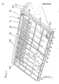
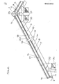
- the gable roof shown in the drawing consists of rafters .3 which run from the ridge 1 to the eaves 2 and which rest on the ridge purlin 4 and the foot purlin 5.
- 6 is a pair of pliers on which the ridge purlin 4 rests.
- the roof formwork 7 consisting of individual boards is nailed to the outside of the rafters 3, to which the roofing felt 8 is applied as a sealing roof covering.
- the roof corresponds to the roof construction that is almost exclusively implemented nowadays, especially in multi-family and single-family houses.
- a thermally insulating underlayer 9, for example made of rock wool panels, is now applied to the roofing felt 8. Furthermore, in the direction from the ridge 1 to the eaves 2 extending boards 10 and at the first and first end of the roof parallel to the ridge 1 extending boards 11, 11 are laid on the roofing felt 8 or the roof formwork 7 and fastened thereon.
- the boards 10 . 11 can be impregnated against fire and putrefaction.
- the coated black collector plate 12 / preferably made of aluminum, is applied to the roof in large lengths.
- the individual tracks of the collector plate. 12 are mutually sealed with heat-resistant sealing tapes.
- the sheet size of the K ollektorblechbahnen 12 may be, for example, 6 x 1 m.
- the beams 13 and 14 and 15 are fastened, for example, to the underlying roof formwork 7 by means of frame screws 16, the heads of which are countersunk in recesses 17 in the beams 13, 14 and 15.
- stiffening profiles 18 running parallel to the ridge, which are embedded in the beams 13 running from the ridge 1 to the eaves 2.
- the stiffening profiles 18 are preferably T-profiles, for example made of aluminum or galvanized steel. Their number depends on the expected snow and wind pressure that acts on the roof.
- the bars 13 extending from the ridge 1 to the eaves 2 are arranged at a distance from the bars 15 and 14 running parallel to the ridge 1 at the eaves and ridge-side roof ends, forming channels 19 and 20, respectively.
- the channels 19 and 20 are also bridged by preferably T-profiles 21 made of aluminum or galvanized steel, which are screwed into the beams 13 which extend in the direction from the ridge 1 to the eaves 2 (FIG. 1).
- the translucent cover 22 is laid, which preferably consists of hollow polycarbonate sheets.
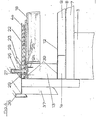
- the cover or the hollow plates 22 can be fastened with the clamping profile device 23 shown in FIG vertical leg of the T-profile 25 sliding U-profile 26 with flanges 27, 28 at its opening facing downwards and a rubber profile 29 arranged between the profiles 25 and 26, the flanges 27, 28 engaging over the adjacent edge of the cover or the adjacent hollow plates 22.
- the clamping profile device 23 is explained in DE-GM 81 26 507.7.
- a supply air distribution duct 30 and a warm air collecting duct 31 run under the roof on each side of the gable roof.
- an air inlet opening 32 leads from the supply air distribution duct 30 into the cavity between the collector plate 12 and the cover 22.
- the air supplied via the air inlet opening 32 flows through the duct 19 and between the beams 13 to the ridge 1 and from there through the duct 20 to an air outlet opening 33, from where it is sucked into the warm air collecting duct 31.
- the air dissipates the solar energy absorbed by the collector plate 12 as heat.
- copper pipe coils 34 can be arranged in the beads of the collector plate 12, the beads being formed in the collector plate 12 before it is laid and the pipe coils 34 being laid in the beads before the cover 22 is installed.
- a heat exchanger (not shown in the drawing) can also be connected downstream of the air outlet opening 33. Instead of process water, another liquid can also be heated, which is supplied, for example, to a heater in which the heat is stored in heat storage masses (for example the ground) for later removal.
- a ridge cap 35 extends over the wedge-shaped Space between the ridge-side beams 13 extending parallel to the ridge 1 on both sides of the gable.
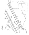
- a A connecting plate 36 is provided on the front formwork 37.
- passages 38 are provided in the beam 15 at the end of the eaves.
- the collector plate 12 extends from the heat-insulating lower layer 9 on the inside of the beams 15 (and 14) and 13 upwards.
- the beams 13, 14 and 15 are provided with a sealing layer 39; likewise, a sealing layer 40 is provided between the T-profiles 18, 21 and the cover 22, as can be seen in particular from FIG. 4.
- a U-profile 41 engages over the eaves-side end of the cover 22 (FIG. 3).
Landscapes
- Engineering & Computer Science (AREA)
- Chemical & Material Sciences (AREA)
- Physics & Mathematics (AREA)
- Life Sciences & Earth Sciences (AREA)
- Sustainable Development (AREA)
- Sustainable Energy (AREA)
- Thermal Sciences (AREA)
- Combustion & Propulsion (AREA)
- Mechanical Engineering (AREA)
- General Engineering & Computer Science (AREA)
- Dispersion Chemistry (AREA)
- Building Environments (AREA)
Applications Claiming Priority (2)
| Application Number | Priority Date | Filing Date | Title |
|---|---|---|---|
| DE3201618 | 1982-01-20 | ||
| DE19823201618 DE3201618A1 (de) | 1982-01-20 | 1982-01-20 | Einrichtung zur gewinnung von waermeenergie aus auf ein dach fallender sonnenstrahlung |
Publications (1)
| Publication Number | Publication Date |
|---|---|
| EP0085860A1 true EP0085860A1 (fr) | 1983-08-17 |
Family
ID=6153464
Family Applications (1)
| Application Number | Title | Priority Date | Filing Date |
|---|---|---|---|
| EP83100445A Withdrawn EP0085860A1 (fr) | 1982-01-20 | 1983-01-19 | Dispositif pour obtenir de l'énergie thermique provenant de la radiation solaire incident sur un toît |
Country Status (2)
| Country | Link |
|---|---|
| EP (1) | EP0085860A1 (fr) |
| DE (1) | DE3201618A1 (fr) |
Cited By (5)
| Publication number | Priority date | Publication date | Assignee | Title |
|---|---|---|---|---|
| DE19615228A1 (de) * | 1996-04-18 | 1997-10-23 | Otto Breitenbach | Solarenergieabsorberdach sowie Solarenergieabsorberwand bzw. -fassade |
| WO2008078084A3 (fr) * | 2006-12-23 | 2008-12-24 | Peter Martin Broatch | Capteurs solaires |
| FR2974375A1 (fr) * | 2011-04-20 | 2012-10-26 | Terreal | Systeme de recuperation des apports solaires sur une toiture traditionnelle en pente |
| GB2498737A (en) * | 2012-01-24 | 2013-07-31 | Tony Camfield | Solar energy capture system |
| EP2653633A1 (fr) * | 2012-04-18 | 2013-10-23 | Terreal | Système de récuperation des apports solaires sur une toiture traditionnelle en pente |
Families Citing this family (6)
| Publication number | Priority date | Publication date | Assignee | Title |
|---|---|---|---|---|
| DE29506798U1 (de) * | 1995-04-21 | 1995-06-29 | Nova Solar Gmbh | Bausatz zur Erstellung eines Daches durch Fertigdachelemente mit integrierten Großkollektoren |
| DE19736002B4 (de) * | 1997-08-19 | 2005-03-03 | Zdjelar Zvonko | Dachziegel-Vakuumkollektor |
| DE102005046471A1 (de) * | 2005-09-22 | 2007-04-05 | Thomas Jahn | Unterdach-Solaranlage |
| DE102009059883A1 (de) | 2009-12-21 | 2011-06-22 | Robert Bosch GmbH, 70469 | Solarkollektor, Fassadenelement und Verfahren zum Betreiben einer Solaranlage |
| DE202011101229U1 (de) | 2011-05-28 | 2012-08-30 | Robert Bosch Gmbh | Sonnenkollektor |
| US10547270B2 (en) | 2016-02-12 | 2020-01-28 | Solarcity Corporation | Building integrated photovoltaic roofing assemblies and associated systems and methods |
Citations (5)
| Publication number | Priority date | Publication date | Assignee | Title |
|---|---|---|---|---|
| DE2826832A1 (de) * | 1977-06-20 | 1979-01-04 | Hastwell | Dachaufbau fuer mit solar-erhitzeranlagen ausruestbare daecher |
| DE2809550A1 (de) * | 1978-03-06 | 1979-09-13 | Schaefer Werke Gmbh | Anlage fuer die gewinnung von sonnenenergie, absorber fuer eine solche anlage und verfahren zur montage des absorbers |
| US4263896A (en) * | 1978-01-10 | 1981-04-28 | Sunhouse, Incorporated | Solar panel |
| DE3000289A1 (de) * | 1980-01-05 | 1981-07-09 | Peter 4224 Hünxe Spielvogel | Verfahren und vorrichtung zur gewinnung bzw. nutzung von urweltwaerme |
| DE8031975U1 (de) * | 1980-12-01 | 1981-12-10 | Piller, Michael, 8229 Piding | Absorberdach |
-
1982
- 1982-01-20 DE DE19823201618 patent/DE3201618A1/de not_active Ceased
-
1983
- 1983-01-19 EP EP83100445A patent/EP0085860A1/fr not_active Withdrawn
Patent Citations (5)
| Publication number | Priority date | Publication date | Assignee | Title |
|---|---|---|---|---|
| DE2826832A1 (de) * | 1977-06-20 | 1979-01-04 | Hastwell | Dachaufbau fuer mit solar-erhitzeranlagen ausruestbare daecher |
| US4263896A (en) * | 1978-01-10 | 1981-04-28 | Sunhouse, Incorporated | Solar panel |
| DE2809550A1 (de) * | 1978-03-06 | 1979-09-13 | Schaefer Werke Gmbh | Anlage fuer die gewinnung von sonnenenergie, absorber fuer eine solche anlage und verfahren zur montage des absorbers |
| DE3000289A1 (de) * | 1980-01-05 | 1981-07-09 | Peter 4224 Hünxe Spielvogel | Verfahren und vorrichtung zur gewinnung bzw. nutzung von urweltwaerme |
| DE8031975U1 (de) * | 1980-12-01 | 1981-12-10 | Piller, Michael, 8229 Piding | Absorberdach |
Cited By (9)
| Publication number | Priority date | Publication date | Assignee | Title |
|---|---|---|---|---|
| DE19615228A1 (de) * | 1996-04-18 | 1997-10-23 | Otto Breitenbach | Solarenergieabsorberdach sowie Solarenergieabsorberwand bzw. -fassade |
| DE19615228C2 (de) * | 1996-04-18 | 2001-02-22 | Otto Breitenbach | Solarenergieabsorberdach sowie Solarenergieabsorberwand bzw. -fassade |
| WO2008078084A3 (fr) * | 2006-12-23 | 2008-12-24 | Peter Martin Broatch | Capteurs solaires |
| FR2974375A1 (fr) * | 2011-04-20 | 2012-10-26 | Terreal | Systeme de recuperation des apports solaires sur une toiture traditionnelle en pente |
| WO2012172214A1 (fr) * | 2011-04-20 | 2012-12-20 | Terreal | Systeme de recuperation des apports solaires sur une toiture traditionnelle en pente |
| GB2498737A (en) * | 2012-01-24 | 2013-07-31 | Tony Camfield | Solar energy capture system |
| GB2498737B (en) * | 2012-01-24 | 2017-04-19 | Future Energy Source Ltd | A solar energy capture system |
| EP2653633A1 (fr) * | 2012-04-18 | 2013-10-23 | Terreal | Système de récuperation des apports solaires sur une toiture traditionnelle en pente |
| FR2989708A1 (fr) * | 2012-04-18 | 2013-10-25 | Terreal | Systeme de recuperation des apports solaires sur une toiture traditionnelle en pente |
Also Published As
| Publication number | Publication date |
|---|---|
| DE3201618A1 (de) | 1983-07-28 |
Similar Documents
| Publication | Publication Date | Title |
|---|---|---|
| US8137170B2 (en) | Radiant baffle/collector for roof construction and retrofit | |
| DE102007045889A1 (de) | Solares Energiekomplettsystem | |
| EP0085860A1 (fr) | Dispositif pour obtenir de l'énergie thermique provenant de la radiation solaire incident sur un toît | |
| EP0000543B1 (fr) | Dispositif de construction pour toits ou façades de climatisation et son utilisation comme évaporateur | |
| DE2702939A1 (de) | Blechabdeckung fuer daecher | |
| EP0964967B1 (fr) | Element de toiture | |
| EP1988227B1 (fr) | Toit pour bâtiments | |
| DE3147124C2 (de) | Rohrbündel-Wärmetauscher | |
| DE3026217A1 (de) | Vorrichtung zur erwaermung einer fluessigkeit unter ausnutzung der sonnenenergie | |
| CH626438A5 (en) | Heat-exchange device on a building | |
| CH651345A5 (de) | Energiedach. | |
| EP0014355A1 (fr) | Echangeur de chaleur pour récupérer la chaleur de l'environnement | |
| WO1998017880A1 (fr) | Element de toiture | |
| DE102005049222A1 (de) | Vorrichtung zur Dacheindeckung mit Solarabsorber | |
| EP0026808B1 (fr) | Couverture de toit ou revêtement de façade et procédé pour la fabrication d'un panneau pour cette couverture de toit ou ce revêtement de façade | |
| DE2925293C3 (de) | Dacheindeckung | |
| DE2913490A1 (de) | Absorberdach | |
| DE3019388A1 (de) | Vorrichtung zur erwaermung einer fluessigkeit mittels sonnenenergie | |
| DE102007031601A1 (de) | Gebäudeteil mit Wärmeaufnehmer | |
| DE102023113480A1 (de) | Dachaufbau mit Photovoltaikmodul und Luftführung | |
| DE2613631A1 (de) | Autonome sonnenenergieheizung im baukastensystem mit speicherpool und grossflaechen-raumheizung | |
| DE3140235A1 (de) | Dachabdeckung | |
| EP4573652A1 (fr) | Structure de toit comprenant des modules photovoltaïques | |
| DE2951285A1 (de) | Dacheindeckung als energiesammler | |
| DE2935001A1 (de) | Dachabdeckung |
Legal Events
| Date | Code | Title | Description |
|---|---|---|---|
| PUAI | Public reference made under article 153(3) epc to a published international application that has entered the european phase |
Free format text: ORIGINAL CODE: 0009012 |
|
| AK | Designated contracting states |
Designated state(s): AT BE CH DE FR IT LI NL |
|
| STAA | Information on the status of an ep patent application or granted ep patent |
Free format text: STATUS: THE APPLICATION IS DEEMED TO BE WITHDRAWN |
|
| 18D | Application deemed to be withdrawn |
Effective date: 19840725 |
|
| NLV4 | Nl: lapsed or anulled due to non-payment of the annual fee | ||
| RIN1 | Information on inventor provided before grant (corrected) |
Inventor name: FELDGRILL, FRANZ |