EP0086024B1 - Lichtleiter zur Flüssigkeitssignalisierung und Kabel mit einem derartigen Leiter - Google Patents
Lichtleiter zur Flüssigkeitssignalisierung und Kabel mit einem derartigen Leiter Download PDFInfo
- Publication number
- EP0086024B1 EP0086024B1 EP83200187A EP83200187A EP0086024B1 EP 0086024 B1 EP0086024 B1 EP 0086024B1 EP 83200187 A EP83200187 A EP 83200187A EP 83200187 A EP83200187 A EP 83200187A EP 0086024 B1 EP0086024 B1 EP 0086024B1
- Authority
- EP
- European Patent Office
- Prior art keywords
- light guide
- liquid
- signalling
- cable
- wave
- Prior art date
- Legal status (The legal status is an assumption and is not a legal conclusion. Google has not performed a legal analysis and makes no representation as to the accuracy of the status listed.)
- Expired
Links
- 239000007788 liquid Substances 0.000 title claims abstract description 23
- 238000001514 detection method Methods 0.000 title 1
- 230000011664 signaling Effects 0.000 claims abstract description 28
- 230000008961 swelling Effects 0.000 claims abstract description 27
- 239000004020 conductor Substances 0.000 claims abstract description 24
- 239000000758 substrate Substances 0.000 claims abstract description 8
- 239000000463 material Substances 0.000 claims description 12
- 230000003287 optical effect Effects 0.000 claims description 5
- 239000012528 membrane Substances 0.000 claims description 3
- 239000000843 powder Substances 0.000 abstract description 15
- 239000003365 glass fiber Substances 0.000 abstract description 6
- 230000001681 protective effect Effects 0.000 abstract 1
- 238000005253 cladding Methods 0.000 description 5
- 238000000034 method Methods 0.000 description 3
- 239000013307 optical fiber Substances 0.000 description 3
- 238000010521 absorption reaction Methods 0.000 description 2
- 239000000835 fiber Substances 0.000 description 2
- 238000004519 manufacturing process Methods 0.000 description 2
- 229910000831 Steel Inorganic materials 0.000 description 1
- 230000000254 damaging effect Effects 0.000 description 1
- 230000000694 effects Effects 0.000 description 1
- 239000000839 emulsion Substances 0.000 description 1
- 239000003673 groundwater Substances 0.000 description 1
- 238000000465 moulding Methods 0.000 description 1
- 230000000149 penetrating effect Effects 0.000 description 1
- 239000010453 quartz Substances 0.000 description 1
- 238000010079 rubber tapping Methods 0.000 description 1
- VYPSYNLAJGMNEJ-UHFFFAOYSA-N silicon dioxide Inorganic materials O=[Si]=O VYPSYNLAJGMNEJ-UHFFFAOYSA-N 0.000 description 1
- 239000010959 steel Substances 0.000 description 1
- 229920002994 synthetic fiber Polymers 0.000 description 1
Images
Classifications
-
- G—PHYSICS
- G01—MEASURING; TESTING
- G01N—INVESTIGATING OR ANALYSING MATERIALS BY DETERMINING THEIR CHEMICAL OR PHYSICAL PROPERTIES
- G01N19/00—Investigating materials by mechanical methods
- G01N19/10—Measuring moisture content, e.g. by measuring change in length of hygroscopic filament; Hygrometers
-
- G—PHYSICS
- G01—MEASURING; TESTING
- G01M—TESTING STATIC OR DYNAMIC BALANCE OF MACHINES OR STRUCTURES; TESTING OF STRUCTURES OR APPARATUS, NOT OTHERWISE PROVIDED FOR
- G01M3/00—Investigating fluid-tightness of structures
- G01M3/02—Investigating fluid-tightness of structures by using fluid or vacuum
- G01M3/04—Investigating fluid-tightness of structures by using fluid or vacuum by detecting the presence of fluid at the leakage point
- G01M3/042—Investigating fluid-tightness of structures by using fluid or vacuum by detecting the presence of fluid at the leakage point by using materials which expand, contract, disintegrate, or decompose in contact with a fluid
- G01M3/045—Investigating fluid-tightness of structures by using fluid or vacuum by detecting the presence of fluid at the leakage point by using materials which expand, contract, disintegrate, or decompose in contact with a fluid with electrical detection means
- G01M3/047—Investigating fluid-tightness of structures by using fluid or vacuum by detecting the presence of fluid at the leakage point by using materials which expand, contract, disintegrate, or decompose in contact with a fluid with electrical detection means with photo-electrical detection means, e.g. using optical fibres
-
- G—PHYSICS
- G02—OPTICS
- G02B—OPTICAL ELEMENTS, SYSTEMS OR APPARATUS
- G02B6/00—Light guides; Structural details of arrangements comprising light guides and other optical elements, e.g. couplings
- G02B6/44—Mechanical structures for providing tensile strength and external protection for fibres, e.g. optical transmission cables
- G02B6/4401—Optical cables
- G02B6/4415—Cables for special applications
-
- G—PHYSICS
- G02—OPTICS
- G02B—OPTICAL ELEMENTS, SYSTEMS OR APPARATUS
- G02B6/00—Light guides; Structural details of arrangements comprising light guides and other optical elements, e.g. couplings
- G02B6/44—Mechanical structures for providing tensile strength and external protection for fibres, e.g. optical transmission cables
- G02B6/4439—Auxiliary devices
- G02B6/4469—Security aspects
Definitions
- the invention relates to a signalling conductor for signalling the presence of a liquid comprising a light guide, which light guide is enwrapped in a perforated tubular element comprising material swelling under the influence of said liquid and by swelling mechanically deforming said light guide.
- the invention also relates to a cable comprising such signalling conductor.
- Proposals for a signalling conductor of that kind, and a cable comprising such a signalling conductor are known from the German application DE-A-2842077. They were intended so as to avoid the inclusion of an electrically conducting wire in a cable, which mainly comprises light guides, which wire is at the same time used for signalling purposes, including the signalling of liquid, such as ground water, which may have penetrated into the cable.
- Such an inclusion should be avoided because electrical conducting wires can be manipulated easier, e.g. for tapping.
- the inclusion of electrical conductors with a plurality of optical conductors arranged in a cable encounters difficulties, and therefore should be avoided.
- Said application suggests a signalling conductor using a special fibre with a quartz core and a plastic cladding, which cladding can contain a material swelling under the contact with liquid. Such contact can cause a mechanical deformation of the cladding, and thus introduce a signal attenuation within the signalling conductor, which can be detected.
- the drawbacks of said proposal are that a light guide has to be produced, which contains a special cladding, that the deformation of the cladding will have a damaging effect on the light guide, and that the attenuation in general will be relatively small, such that the entrance of small amounts of liquid will not be detected.
- the object of the present invention is to provide a signalling conductor which does not have said drawbacks.
- This object is accomplished by means of a signalling conductor of the above kind characterized in that the tubular element comprises a pressure area provided with a wave-shaped pattern formed in such a manner that microbending of the light guide will occur when the light guide is pressed against said pattern by the swelling material after the entrance of a liquid into the tubular element.
- a microbending caused by penetrating liquid results in a very strong attenuation, which can be detected and localized very easily.
- the invention can be advantageously applied in an optical fibre cable with a core with a star-shaped cross-section.
- One or more of the notches, defined by the space between the links of the star can be used to insert an optical light guide and a material which swells under the influence of liquid, according to claim 6.
- Optical fibre cables with a core with a star-shaped cross-section as such are known, e.g. from the applications DE-A-2508315 and EP-A-0026952.
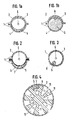
- Fig. 1a shows a sectional view of a preferred embodiment, in which 1 designates a tubular element, here designed with an upper part 2 comprising a wave-shaped pattern 3, and a lower part 4 containing a swelling powder 5.
- a light guide 6 is mainly inserted loose in the tubular element 1.
- the parts 2 and 4 can be made of a suitable synthetic material, such as polyvinyldifluoride (PVDF).
- PVDF polyvinyldifluoride
- the wave-shaped pattern 3, the rib structure of which is in a position transversely to the longitudinal direction, can be rolled in in the course of the moulding process.
- the swelling powder 5 in the lower part 4 can have the form of an emulsion or it can be applied to a suitable substrate, such as a non-woven glass-fibre strip.
- the quantity of swelling powder supplied should be such that when liquid is absorbed, the light guide in the relevant portion will be deformed, due to the expansion of the swelling powder, to such an extent that signalling can take place, whereas the tubular element itself remains intact.
- the volume of a suitable swelling powder becomes about 20 times as large. The absorption of liquid takes place e.g. through perforations in the lower part 4 and/or in the upper part 2.
- Fig. 1 shows a sectional view of the same optical guide, but now after the absorption of liquid.
- the swelling powder 5 has filled the tubular element 1 almost entirely and presses the light guide 6 against the wave-shaped pattern 3. It is remarked that even when the tubular element is not provided with a wave-shaped pattern, the structure of the light guide 6 ensures the observation of already an attenuation of the light signal in the light guide 6 of at least 0.5 dB/m. If the light guide is pressed on such a wave-shaped pattern that microbending is caused, an attenuation to 10 dB will be measured when liquid is absorbed over a distance of about 10 cm.
- the attenuation and the place where the liquid enters can be measured according to known methods, such as the back-scatter method.
- Fig. 3 shows a third embodiment in which the whole inner periphery of the tubular element 1 is provided with the wave-shaped pattern 3, which can have the shape of separate ribs as well as the shape of a helical line with a suitable pitch.
- the swelling powder 5 is here applied to a rolled-up substrate 8, which can be easily included in the tubular element 1 in the course of the manufacturing process. When liquid enters, the substrate 8 can unroll.
- Fig. 4 shows an embodiment of a cable which has a star-shaped core 9, in consequence of which axially running notches 10 are formed.
- a glass fibre can be inserted in each of these notches, whereas one of the notches comprises the signalling conductor.
- the star-shaped core 9 will be closed off by a sheath 11.
- the swelling powder 5 can be applied to a substrate or not.
- the wave-shaped pattern 3 can be mounted either on a separate membrane between the light guide 6 and the swelling powder 5 or on the bottom of the notch.
Landscapes
- Physics & Mathematics (AREA)
- General Physics & Mathematics (AREA)
- Optics & Photonics (AREA)
- Immunology (AREA)
- Health & Medical Sciences (AREA)
- Biochemistry (AREA)
- General Health & Medical Sciences (AREA)
- Chemical & Material Sciences (AREA)
- Life Sciences & Earth Sciences (AREA)
- Pathology (AREA)
- Analytical Chemistry (AREA)
- Engineering & Computer Science (AREA)
- Computer Security & Cryptography (AREA)
- Light Guides In General And Applications Therefor (AREA)
- Optical Fibers, Optical Fiber Cores, And Optical Fiber Bundles (AREA)
- Geophysics And Detection Of Objects (AREA)
- Endoscopes (AREA)
- Rigid Pipes And Flexible Pipes (AREA)
- Communication Cables (AREA)
Claims (6)
Priority Applications (1)
| Application Number | Priority Date | Filing Date | Title |
|---|---|---|---|
| AT83200187T ATE24767T1 (de) | 1982-02-09 | 1983-02-04 | Lichtleiter zur fluessigkeitssignalisierung und kabel mit einem derartigen leiter. |
Applications Claiming Priority (2)
| Application Number | Priority Date | Filing Date | Title |
|---|---|---|---|
| NL8200495A NL8200495A (nl) | 1982-02-09 | 1982-02-09 | Lichtgeleider voor vochtsignalering en kabel omvattende zulk een geleider. |
| NL8200495 | 1982-02-09 |
Publications (2)
| Publication Number | Publication Date |
|---|---|
| EP0086024A1 EP0086024A1 (de) | 1983-08-17 |
| EP0086024B1 true EP0086024B1 (de) | 1987-01-07 |
Family
ID=19839228
Family Applications (1)
| Application Number | Title | Priority Date | Filing Date |
|---|---|---|---|
| EP83200187A Expired EP0086024B1 (de) | 1982-02-09 | 1983-02-04 | Lichtleiter zur Flüssigkeitssignalisierung und Kabel mit einem derartigen Leiter |
Country Status (6)
| Country | Link |
|---|---|
| US (1) | US4596443A (de) |
| EP (1) | EP0086024B1 (de) |
| JP (1) | JPS58144802A (de) |
| AT (1) | ATE24767T1 (de) |
| DE (2) | DE3368995D1 (de) |
| NL (1) | NL8200495A (de) |
Families Citing this family (28)
| Publication number | Priority date | Publication date | Assignee | Title |
|---|---|---|---|---|
| US4729627A (en) * | 1983-08-15 | 1988-03-08 | Sumitomo Electric Industries, Ltd. | Optical fiber cable for detecting low temperature |
| US4807962A (en) * | 1986-03-06 | 1989-02-28 | American Telephone And Telegraph Company, At&T Bell Laboratories | Optical fiber cable having fluted strength member core |
| JPH07113695B2 (ja) * | 1986-04-21 | 1995-12-06 | 住友電気工業株式会社 | 防水形光ケ−ブルおよびその製造方法 |
| US5082719A (en) * | 1987-10-30 | 1992-01-21 | At&T Bell Laboratories | Water resistant communications cable |
| US4815813A (en) * | 1987-10-30 | 1989-03-28 | American Telephone And Telegraph Company | Water resistant communications cable |
| US4867526A (en) * | 1987-10-30 | 1989-09-19 | American Telephone And Telegraph Company, At&T Bell Laboratories | Water resistant communications cable |
| US4850672A (en) * | 1988-02-19 | 1989-07-25 | Siecor Corporation | Strain compensated fiber optic cable |
| US4909592A (en) * | 1988-09-29 | 1990-03-20 | American Telephone And Telegraph Company, At&T Bell Laboratories | Communication cable having water blocking provisions in core |
| DE8902073U1 (de) * | 1989-02-22 | 1989-07-06 | Kabelwerke Reinshagen Gmbh, 5600 Wuppertal | Kabel zur Ortung von Flüssigkeiten |
| FI904862A7 (fi) * | 1989-10-09 | 1991-04-10 | Sumitomo Electric Industries | Vedenkestävä optinen kuitukaapeli |
| US5193134A (en) * | 1991-03-08 | 1993-03-09 | Pirelli Cavi S.P.A. | Grooved-core cable for use with ribbon optical fibres and process to make the same |
| FR2680004B1 (fr) * | 1991-08-02 | 1993-10-22 | Alcatel Cable | Capteur d'humidite a fibre optique. |
| US5378889A (en) * | 1993-09-23 | 1995-01-03 | California Lightwave Laboratories, Inc. | Method and apparatus for detecting hydrocarbon fuels in a vapor state with an absorber-expander member |
| US5388175A (en) * | 1994-01-25 | 1995-02-07 | Siecor Corporation | Optical cable having powder embedded in plastic surfaces |
| KR970019133U (ko) * | 1995-10-31 | 1997-05-26 | 광케이블의 볼록형 슬롯 코어 형상 | |
| US5757988A (en) * | 1995-12-05 | 1998-05-26 | Mark Products, Inc. | Optical fiber sensor utilizing a swellable detector material |
| US5796097A (en) * | 1997-03-05 | 1998-08-18 | California Lightwave Laboratories, Inc. | Chemical sensor and method |
| US6178278B1 (en) | 1997-11-13 | 2001-01-23 | Alcatel | Indoor/outdoor dry optical fiber cable |
| US6169834B1 (en) | 1998-05-13 | 2001-01-02 | Alcatel | Slotted composite cable having a cable housing with a tubular opening for copper pairs and a slot for an optical fiber |
| US6253012B1 (en) | 1998-11-12 | 2001-06-26 | Alcatel | Cycled fiber lock for cross-functional totally dry optical fiber loose tube cable |
| US6424772B1 (en) | 1999-11-30 | 2002-07-23 | Corning Cable Systems, Llc | Fiber optic cable product and associated fabrication method and apparatus |
| US6341615B1 (en) | 2000-09-13 | 2002-01-29 | Air Products And Chemicals, Inc. | Self-cleaning vacuum purge system |
| CA2373582A1 (en) * | 2001-02-28 | 2002-08-28 | Asahi Glass Company, Limited | Optical fiber cable |
| US7630605B2 (en) * | 2007-06-26 | 2009-12-08 | Corning Cable Systems Llc | Optical fiber assemblies having relatively low-levels of water-swellable powder and methods therefor |
| US7916989B2 (en) | 2008-07-31 | 2011-03-29 | Corning Cable Systems Llc | Optical fiber assemblies having a powder or powder blend at least partially mechanically attached |
| EP2318872B1 (de) | 2008-08-15 | 2013-03-20 | Corning Cable Systems LLC | Faseroptische baugruppen und verfahren und vorrichtungen zu ihrer herstellung |
| US8625946B2 (en) * | 2010-03-11 | 2014-01-07 | Adc Telecommunications, Inc. | Optical fiber assembly |
| GB2504446B (en) * | 2011-06-20 | 2017-08-30 | Shell Int Res Maatschhappij B V | Fibre optic cable with increased directional sensitivity |
Citations (1)
| Publication number | Priority date | Publication date | Assignee | Title |
|---|---|---|---|---|
| EP0026952A1 (de) * | 1979-10-08 | 1981-04-15 | Koninklijke Philips Electronics N.V. | Kabel mit optischen Fasern |
Family Cites Families (14)
| Publication number | Priority date | Publication date | Assignee | Title |
|---|---|---|---|---|
| US3786681A (en) * | 1971-03-04 | 1974-01-22 | Sci Systems Inc | Electromagnetic wave modulation and measurement system and method |
| GB1409303A (en) * | 1972-09-20 | 1975-10-08 | Post Office | Optical strands |
| US3931518A (en) * | 1974-11-11 | 1976-01-06 | Bell Telephone Laboratories, Incorporated | Optical fiber power taps employing mode coupling means |
| DE2508315C2 (de) * | 1975-02-24 | 1984-09-06 | Siemens AG, 1000 Berlin und 8000 München | Nachrichtenkabel mit Lichtleiter bzw. Lichtleiterbündel als Übertragungselemente |
| US4019051A (en) * | 1975-12-24 | 1977-04-19 | Bell Telephone Laboratories, Incorporated | Directional optical waveguide couplers |
| FR2337411A1 (fr) * | 1975-12-30 | 1977-07-29 | Lignes Telegraph Telephon | Cable composite de transmission a longue distance |
| JPS5620018Y2 (de) * | 1976-09-01 | 1981-05-13 | ||
| AU4223778A (en) * | 1977-12-12 | 1979-06-21 | Pedro B Macedo | Optical waveguide sensor |
| US4270049A (en) * | 1978-06-12 | 1981-05-26 | Ishikawajima-Harima Jukogyo Kabushiki Kaisha | Liquid leakage detection system |
| DE2842077C2 (de) * | 1978-09-27 | 1986-02-06 | Siemens AG, 1000 Berlin und 8000 München | Optisch überwachtes Lichtwellenleiterkabel |
| US4419157A (en) * | 1980-05-13 | 1983-12-06 | Industrie Pirelli Societa Per Azioni | Process and apparatus for manufacturing telecommunication cables filled with expansible powder |
| US4361381A (en) * | 1980-10-06 | 1982-11-30 | Northern Telecom Limited | Optical cable |
| JPS57128304A (en) * | 1981-01-09 | 1982-08-09 | Furukawa Electric Co Ltd:The | Nonmetallic optical cable |
| US4401366A (en) * | 1981-04-30 | 1983-08-30 | Northern Telecom Limited | Powder filled fiber optic cable |
-
1982
- 1982-02-09 NL NL8200495A patent/NL8200495A/nl not_active Application Discontinuation
-
1983
- 1983-02-04 DE DE8383200187T patent/DE3368995D1/de not_active Expired
- 1983-02-04 DE DE198383200187T patent/DE86024T1/de active Pending
- 1983-02-04 AT AT83200187T patent/ATE24767T1/de not_active IP Right Cessation
- 1983-02-04 EP EP83200187A patent/EP0086024B1/de not_active Expired
- 1983-02-08 JP JP58018259A patent/JPS58144802A/ja active Pending
-
1985
- 1985-04-18 US US06/724,048 patent/US4596443A/en not_active Expired - Fee Related
Patent Citations (1)
| Publication number | Priority date | Publication date | Assignee | Title |
|---|---|---|---|---|
| EP0026952A1 (de) * | 1979-10-08 | 1981-04-15 | Koninklijke Philips Electronics N.V. | Kabel mit optischen Fasern |
Non-Patent Citations (1)
| Title |
|---|
| J. N. FIELDS: "Attenuation of a parabolic-index fiber with periodic bends" * |
Also Published As
| Publication number | Publication date |
|---|---|
| EP0086024A1 (de) | 1983-08-17 |
| JPS58144802A (ja) | 1983-08-29 |
| NL8200495A (nl) | 1983-09-01 |
| US4596443A (en) | 1986-06-24 |
| ATE24767T1 (de) | 1987-01-15 |
| DE86024T1 (de) | 1983-11-10 |
| DE3368995D1 (en) | 1987-02-12 |
Similar Documents
| Publication | Publication Date | Title |
|---|---|---|
| EP0086024A1 (de) | Lichtleiter zur Flüssigkeitssignalisierung und Kabel mit einem derartigen Leiter | |
| US4862146A (en) | Detection apparatus | |
| CA1128166A (en) | Security system | |
| GB2157847A (en) | Underwater optical fibre cable | |
| BE887874A (fr) | Tuyau flexible en matiere plastique et son procede de fabrication | |
| KR910006743A (ko) | 수중용 광섬유케이블 유니트 | |
| KR840000809A (ko) | 광 섬유 복합가공선 | |
| DE3177250D1 (de) | Verfahren zur herstellung einer halbleiteranordnung mit dielektrischen isolationszonen. | |
| KR850008415A (ko) | 원거리통신용 해저 광학섬유 전선 | |
| KR860006709A (ko) | 해저용 광섬유 케이블 | |
| JPH08507390A (ja) | 細い導線、特に光ファイバーを有するケーブル、それを製造する方法および装置 | |
| US20020085819A1 (en) | Optical temperature sensing arrangement for towed cable | |
| US2823279A (en) | Detector for highway vehicle traffic | |
| FR2424612A1 (fr) | Cable electrique ou optique resistant a la traction et comportant une gaine en matiere plastique renforcee | |
| FR2443694A1 (fr) | Conducteur a ame en fibre optique et cable comportant un tel conducteur | |
| NL7709656A (nl) | Werkwijze om de breuk van een glasvezeldraad te ontdekken. | |
| DE19520826B4 (de) | Geschirmtes Starkstromkabel mit Temperatur- und Wassersensor | |
| FR2274123A1 (fr) | Cable plat opto-electrique, son procede de fabrication, et dispositif de mise en oeuvre de ce procede | |
| US4967040A (en) | Screened electric cable provided with zones for rapid parallel connection | |
| ATE6105T1 (de) | Elektrisches kabel mit mehrdraehtigem leiter und feuchtigkeitssperre. | |
| EP0906584B1 (de) | Anordnung zum übertragen von licht zwischen zwei auf unterschiedlichem elektrischem potential liegenden orten und verfahren zum herstellen einer solchen anordnung | |
| GB392416A (en) | Improvements in or relating to electric cables | |
| EP0018757B1 (de) | Massnahme zur Verbesserung leitender Kabel, und Verfahren zum Aufschlitzen der Kunststoffhülle eines leitenden Kabels | |
| KR910005954Y1 (ko) | 경보장치의 감지부용 광섬유 케이블 | |
| GB2031605B (en) | Crimped connector assembly for fibre optic cables or the like |
Legal Events
| Date | Code | Title | Description |
|---|---|---|---|
| PUAI | Public reference made under article 153(3) epc to a published international application that has entered the european phase |
Free format text: ORIGINAL CODE: 0009012 |
|
| AK | Designated contracting states |
Designated state(s): AT BE CH DE FR GB IT LI LU SE |
|
| TCAT | At: translation of patent claims filed | ||
| EL | Fr: translation of claims filed | ||
| ITCL | It: translation for ep claims filed |
Representative=s name: STUDIO MASSARI S.R.L. |
|
| DET | De: translation of patent claims | ||
| 17P | Request for examination filed |
Effective date: 19840210 |
|
| GRAA | (expected) grant |
Free format text: ORIGINAL CODE: 0009210 |
|
| AK | Designated contracting states |
Kind code of ref document: B1 Designated state(s): AT BE CH DE FR GB IT LI LU SE |
|
| REF | Corresponds to: |
Ref document number: 24767 Country of ref document: AT Date of ref document: 19870115 Kind code of ref document: T |
|
| PGFP | Annual fee paid to national office [announced via postgrant information from national office to epo] |
Ref country code: AT Payment date: 19870210 Year of fee payment: 5 |
|
| REF | Corresponds to: |
Ref document number: 3368995 Country of ref document: DE Date of ref document: 19870212 |
|
| PG25 | Lapsed in a contracting state [announced via postgrant information from national office to epo] |
Ref country code: LU Free format text: LAPSE BECAUSE OF NON-PAYMENT OF DUE FEES Effective date: 19870228 |
|
| ITF | It: translation for a ep patent filed | ||
| ET | Fr: translation filed | ||
| PLBE | No opposition filed within time limit |
Free format text: ORIGINAL CODE: 0009261 |
|
| STAA | Information on the status of an ep patent application or granted ep patent |
Free format text: STATUS: NO OPPOSITION FILED WITHIN TIME LIMIT |
|
| 26N | No opposition filed | ||
| PG25 | Lapsed in a contracting state [announced via postgrant information from national office to epo] |
Ref country code: AT Effective date: 19880204 |
|
| PG25 | Lapsed in a contracting state [announced via postgrant information from national office to epo] |
Ref country code: SE Effective date: 19880205 |
|
| PG25 | Lapsed in a contracting state [announced via postgrant information from national office to epo] |
Ref country code: LI Effective date: 19880229 Ref country code: CH Effective date: 19880229 |
|
| BERE | Be: lapsed |
Owner name: STAAT DER NEDERLANDEN (STAATSBEDRIJF DER POSTERIJ Effective date: 19880228 |
|
| PG25 | Lapsed in a contracting state [announced via postgrant information from national office to epo] |
Ref country code: FR Free format text: LAPSE BECAUSE OF NON-PAYMENT OF DUE FEES Effective date: 19881028 |
|
| REG | Reference to a national code |
Ref country code: CH Ref legal event code: PL |
|
| GBPC | Gb: european patent ceased through non-payment of renewal fee | ||
| PG25 | Lapsed in a contracting state [announced via postgrant information from national office to epo] |
Ref country code: GB Free format text: LAPSE BECAUSE OF NON-PAYMENT OF DUE FEES Effective date: 19881122 |
|
| PG25 | Lapsed in a contracting state [announced via postgrant information from national office to epo] |
Ref country code: DE Effective date: 19881201 |
|
| REG | Reference to a national code |
Ref country code: FR Ref legal event code: ST |
|
| PG25 | Lapsed in a contracting state [announced via postgrant information from national office to epo] |
Ref country code: BE Effective date: 19890228 |
|
| EUG | Se: european patent has lapsed |
Ref document number: 83200187.9 Effective date: 19880927 |