EP0086050B1 - Verfahren und Gerät zum Ausheben von Gräben - Google Patents
Verfahren und Gerät zum Ausheben von Gräben Download PDFInfo
- Publication number
- EP0086050B1 EP0086050B1 EP83300332A EP83300332A EP0086050B1 EP 0086050 B1 EP0086050 B1 EP 0086050B1 EP 83300332 A EP83300332 A EP 83300332A EP 83300332 A EP83300332 A EP 83300332A EP 0086050 B1 EP0086050 B1 EP 0086050B1
- Authority
- EP
- European Patent Office
- Prior art keywords
- wheel
- track
- scoops
- excavating
- boom
- Prior art date
- Legal status (The legal status is an assumption and is not a legal conclusion. Google has not performed a legal analysis and makes no representation as to the accuracy of the status listed.)
- Expired
Links
- 238000000034 method Methods 0.000 title claims description 7
- 239000000463 material Substances 0.000 claims abstract description 23
- 238000009412 basement excavation Methods 0.000 abstract description 3
- 230000002093 peripheral effect Effects 0.000 abstract 1
- 238000005266 casting Methods 0.000 description 3
- 230000000694 effects Effects 0.000 description 3
- 238000010276 construction Methods 0.000 description 2
- 230000006378 damage Effects 0.000 description 2
- 244000025254 Cannabis sativa Species 0.000 description 1
- 230000015572 biosynthetic process Effects 0.000 description 1
- 238000004140 cleaning Methods 0.000 description 1
- 238000012423 maintenance Methods 0.000 description 1
- XLYOFNOQVPJJNP-UHFFFAOYSA-N water Substances O XLYOFNOQVPJJNP-UHFFFAOYSA-N 0.000 description 1
Images

Classifications
-
- E—FIXED CONSTRUCTIONS
- E02—HYDRAULIC ENGINEERING; FOUNDATIONS; SOIL SHIFTING
- E02F—DREDGING; SOIL-SHIFTING
- E02F3/00—Dredgers; Soil-shifting machines
- E02F3/04—Dredgers; Soil-shifting machines mechanically-driven
- E02F3/18—Dredgers; Soil-shifting machines mechanically-driven with digging wheels turning round an axis, e.g. bucket-type wheels
- E02F3/181—Dredgers; Soil-shifting machines mechanically-driven with digging wheels turning round an axis, e.g. bucket-type wheels including a conveyor
-
- E—FIXED CONSTRUCTIONS
- E01—CONSTRUCTION OF ROADS, RAILWAYS, OR BRIDGES
- E01B—PERMANENT WAY; PERMANENT-WAY TOOLS; MACHINES FOR MAKING RAILWAYS OF ALL KINDS
- E01B27/00—Placing, renewing, working, cleaning, or taking-up the ballast, with or without concurrent work on the track; Devices therefor; Packing sleepers
- E01B27/06—Renewing or cleaning the ballast in situ, with or without concurrent work on the track
- E01B27/10—Renewing or cleaning the ballast in situ, with or without concurrent work on the track without taking-up track
- E01B27/107—Renewing or cleaning the ballast in situ, with or without concurrent work on the track without taking-up track along between the tracks only
-
- E—FIXED CONSTRUCTIONS
- E02—HYDRAULIC ENGINEERING; FOUNDATIONS; SOIL SHIFTING
- E02F—DREDGING; SOIL-SHIFTING
- E02F3/00—Dredgers; Soil-shifting machines
- E02F3/04—Dredgers; Soil-shifting machines mechanically-driven
- E02F3/18—Dredgers; Soil-shifting machines mechanically-driven with digging wheels turning round an axis, e.g. bucket-type wheels
-
- E—FIXED CONSTRUCTIONS
- E02—HYDRAULIC ENGINEERING; FOUNDATIONS; SOIL SHIFTING
- E02F—DREDGING; SOIL-SHIFTING
- E02F3/00—Dredgers; Soil-shifting machines
- E02F3/04—Dredgers; Soil-shifting machines mechanically-driven
- E02F3/18—Dredgers; Soil-shifting machines mechanically-driven with digging wheels turning round an axis, e.g. bucket-type wheels
- E02F3/186—Dredgers; Soil-shifting machines mechanically-driven with digging wheels turning round an axis, e.g. bucket-type wheels with the axis being substantially parallel to the direction of travel
-
- E—FIXED CONSTRUCTIONS
- E02—HYDRAULIC ENGINEERING; FOUNDATIONS; SOIL SHIFTING
- E02F—DREDGING; SOIL-SHIFTING
- E02F3/00—Dredgers; Soil-shifting machines
- E02F3/04—Dredgers; Soil-shifting machines mechanically-driven
- E02F3/18—Dredgers; Soil-shifting machines mechanically-driven with digging wheels turning round an axis, e.g. bucket-type wheels
- E02F3/20—Dredgers; Soil-shifting machines mechanically-driven with digging wheels turning round an axis, e.g. bucket-type wheels with tools that only loosen the material, i.e. mill-type wheels
-
- E—FIXED CONSTRUCTIONS
- E02—HYDRAULIC ENGINEERING; FOUNDATIONS; SOIL SHIFTING
- E02F—DREDGING; SOIL-SHIFTING
- E02F3/00—Dredgers; Soil-shifting machines
- E02F3/04—Dredgers; Soil-shifting machines mechanically-driven
- E02F3/18—Dredgers; Soil-shifting machines mechanically-driven with digging wheels turning round an axis, e.g. bucket-type wheels
- E02F3/22—Component parts
- E02F3/24—Digging wheels; Digging elements of wheels; Drives for wheels
- E02F3/243—Digging wheels; Digging elements of wheels; Drives for wheels wheels rotatable in both directions
-
- E—FIXED CONSTRUCTIONS
- E02—HYDRAULIC ENGINEERING; FOUNDATIONS; SOIL SHIFTING
- E02F—DREDGING; SOIL-SHIFTING
- E02F9/00—Component parts of dredgers or soil-shifting machines, not restricted to one of the kinds covered by groups E02F3/00 - E02F7/00
- E02F9/02—Travelling-gear, e.g. associated with slewing gears
- E02F9/022—Travelling-gear, e.g. associated with slewing gears for moving on rails
-
- E—FIXED CONSTRUCTIONS
- E02—HYDRAULIC ENGINEERING; FOUNDATIONS; SOIL SHIFTING
- E02F—DREDGING; SOIL-SHIFTING
- E02F9/00—Component parts of dredgers or soil-shifting machines, not restricted to one of the kinds covered by groups E02F3/00 - E02F7/00
- E02F9/08—Superstructures; Supports for superstructures
- E02F9/0808—Improving mounting or assembling, e.g. frame elements, disposition of all the components on the superstructures
-
- Y—GENERAL TAGGING OF NEW TECHNOLOGICAL DEVELOPMENTS; GENERAL TAGGING OF CROSS-SECTIONAL TECHNOLOGIES SPANNING OVER SEVERAL SECTIONS OF THE IPC; TECHNICAL SUBJECTS COVERED BY FORMER USPC CROSS-REFERENCE ART COLLECTIONS [XRACs] AND DIGESTS
- Y10—TECHNICAL SUBJECTS COVERED BY FORMER USPC
- Y10S—TECHNICAL SUBJECTS COVERED BY FORMER USPC CROSS-REFERENCE ART COLLECTIONS [XRACs] AND DIGESTS
- Y10S37/00—Excavating
- Y10S37/907—Automatic leveling excavators
Definitions
- This invention relates to ditching operations, and in particular to the provision of drainage ditches alongside a railroad track.
- a ditcher for continuously excavating a ditch alongside a railroad track, comprising a support carriage mounted on bogies for travel along the track, a boom being mounted at one end on the support carriage for pivotal movement about a first substantially vertical axis and for angular adjustment relative to the horizontal whereby the other end of the boom can be positioned below the level of the support carriage, an excavating wheel being mounted at the other end of the boom to be driven in rotation about a substantially horizontal rotary axis which is adjustable about a substantially vertical axis, the wheel being provided with excavating scoops for excavating subjacent terrain, and means being provided for conveying excavated material from the wheel for controlled disposal, characterized in that the transverse angular disposition of the support carriage is adjustable relatively to the bogies to maintain the support carriage substantially level regardless of transverse inclination of the track.
- the present invention also provides a method of excavating a ditch alongside a transversely inclined portion of a railroad track comprising the steps of: providing a support carriage which is substantially horizontally oriented on a level portion of the track, an excavating wheel being movably mounted on the support carriage and having an annular array of scoops; rotating the wheel about a horizontal rotary axis while moving the wheel along the track and concurrently causing the scoops at the bottom of the wheel to engage the terrain adjacent the track; and positioning the wheel to have the rotary axis disposed selectively within the range of perpendicular to the longitudinal extent of the track to parallel thereto, whereby the scoops may excavate a ditch correspondingly in the range of a narrow track having a width equal to the transverse extent of the scoops to a wider ditch having a profile corresponding to the circumference of the wheel; characterized in that the angular disposition of the support carriage relatively to the track is adjusted to maintain a level orientation of the support carriage regardless of the transverse inclination of the track.
- the present invention thus comprehends an improved method and apparatus for ditching the terrain alongside a railroad track to provide facilitated, low cost, relatively high speed provision of suitable drainage ditches for effectively improving the life of the ballast and railbed.
- an excavating wheel having an annular array of scoops is used. The wheel is rotated about a horizontal axis while the wheel is moved along the track as on a suitable support car. Rotation of the wheel causes the scoops at the bottom of the wheel to engage the terrain adjacent the track.
- the axis of the wheel is selectively caused to extend within the range of perpendicular to the longitudinal extent of the track to substantially parallel thereto, whereby the scoops may excavate a ditch correspondingly in the range of a narrow trench having a width substantially equal to the transverse extent of the scoop to a wide ditch having a profile corresponding to the circumference of the wheel as defined by the scoops.
- Means are provided for causing the wheel to be selectively raised and lowered while concurrently changing the angularity of the axis thereof to the longitudinal extent of track so as to provide optimum arrangement of the ditch as the ditch is formed continuously during the movement of the wheel along the side of the railroad track.
- the operator may suitably control the parameters of the wheel disposition to effect an optimum formation of a drainage ditch within the range of narrow to wide configuration thereof as discussed above.
- the invention further comprehends the conveying of the excavated material from the scoops of the excavating wheel for suitable disposal.
- the excavated material is dropped from a top position of the wheel onto a subjacent belt conveyor which carries the excavated material to a discharge conveyor, which may be positioned suitably to discharge the excavated material remotely alongside the track, or to an adjacent hopper car for subsequent disposal at a remote location.
- the wheel is rotated at a speed whcih causes excavated material, at times, to be thrown from the scoop and means are provided for causing rotation of the wheel suitably to a position spaced from the track outwardly of the ditch for improved facilitated disposal without the need for operation of the conveyor means.
- the apparatus includes means for continuously raising and lowering the wheel to accommodate the wheel to the level of the subjacent terrain to be excavated, while at the same time permitting the wheel to be pivoted about a vertical axis so as to cause the axis of rotation of the wheel to be selectively disposed in the range of angularity, as discussed above.
- the wheel in the illustrated embodiment is carried on the distal end of a boom which permits the wheel to be disposed substantially below the level of the support car to engage the subjacent terrain alongside the track over a wide range of subjacent levels.
- the wheel is selectively positionable about the vertical axis at the distal end of the boom so as to extend over a range of angularity to the boom of approximately 90° perpendicular to the longitudinal extent thereof to substantially parallel thereto.
- the wheel is mounted to the distal end of the boom to be selectively disposable on either side of the boom distal end in the use thereof.
- the wheel is reversibly rotatable and is provided with double-ended scoops, permitting excavation in either direction of rotation of the wheel and facilitating the throwing of the scooped material outwardly from the ditch, as discussed above.
- the wheeled support in the illustrated embodiment, comprises a self-powered flatcar, with the trucks thereof adjustably supporting the bed of the flatcar to permit leveling of the bed for further improved operation of the apparatus at all times.
- the flatcar is provided with an outwardly opening recess for accommodating the excavator wheel in a storage position, such as when the apparatus is being moved from one site t& another.
- the ditching method and apparatus of the present invention is extremely simple and economical, while yet providing a highly improved, low cost ditching operation facilitating improved maintenance of a railroad track bed by providing improved drainage thereof.
- a ditcher apparatus generally designated 10 for excavating a ditch alongside a railroad track 11, such as for providing improved drainage of the track bed 12.
- the ditch D may have a cross-sectional configuration within the range of a narrow, deep trench 13 to a shallow, wide ditch 14.
- the invention comprehends the forming of the ditch to have any suitable configuration within this range.
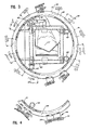
- the invention comprehends forming the drainage ditch by providing an excavator wheel 1-5 having an annular array of excavating scoops 16 on the periphery thereof.
- the wheel is caused to rotate about an axis 17 which, as seen in Figure 1, is normally horizontal, while the wheel is moved along the track so as to cause the scoops at the bottom portion of the wheel to engage the subjacent terrain T adjacent the track.
- the excavator wheel is positionable about a vertical axis 18 at the distal end 19 of a boom 20 so that the wheel rotational axis may extend selectively in the range of perpendicular to the longitudinal extent of the track 11, as seen in Figure 2, or substantially parallel thereto, as seen in Figure 2, or substantially parallel thereto, as seen in Figure 7.
- the wheel is swung about axis 18 by means of a piston cylinder mechanism 21 connected between the wheel and the distal end 19 of the boom, with the wheel being pivotally mounted to the distal end by a suitable pivot structure 22.
- the inboard end 23 of boom 20 is mounted to the bed 24 of a support flatcar on a rotatable platform 25, which, as seen in Figure 2, permits the boom to swing about a vertical axis 26 for selectively adjusting the spacing of the excavator wheel from the side 27 of the support car 24.
- End 23 of the boom is pivoted for swinging vertically about a horizontal pivot 28 mounted to platform 25 by suitable supports 29, and is raised and lowered by means of a hydraulic cylinder 30 extending between the boom and the platform.
- boom 20 may extend angularly downwardly from the support car 24 to cause the scoop 16 of the excavator wheel to engage the subjacent terrain in effecting the ditching operation.
- the wheel may be raised and lowered by suitable operation of the hydraulic cylinder 30 and may be caused to rotate about the vertical axis 22 at boom end 19 by the mechanism 21 so as to cause the excavator wheel to accurately follow the terrain T as the apparatus is moved along the railroad track.
- scoops 16 open radially inwardly so that when they reach an upper portion of the annular travel, as seen in Figure 1, the excavated material drops downwardly therefrom onto a conveyor 31 extending longitudinally through boom 20.
- a suitable chute 32 is provided on a cage 33 for guiding the dropped excavated material onto the conveyor.
- the inboard end 34 of the conveyor transfers the excavated material onto a transverse conveyor 35 which, in turn, transfers the excavated material to a longitudinal conveyor 36 for subsequent transfer to a discharge conveyor 37, all of which conveyors are carried on the flatcar support 24, as seen in Figure 2.
- guide chute 32 may be selectively adjustably mounted to the cage 33 so as to extend away from track 11 to discharge the excavated material dropped from the scoops 16 to a position outwardly of the excavated ditch. Where conditions permit such discharge, the conveyor system need not be operated, thus permitting further facilitated ditching operation.
- scoops 16 are mounted to a ring 38 of the excavator wheel and are provided with leading replaceable teeth 39 for improved facilitated excavation of the terrain T in the operation of the apparatus.
- each of the scoops opens radially inwardly toward wheel axis 17 so that when the scoops are brought to the uppermost position of the annular path of movement, the excavated material therein drops downwardly through the case 33 and chute 32 onto the conveyor 31.
- the ring 38 is guided for movement around the axis 17 by suitable rollers 40 carried on the cage, and is driven by a suitable sprocket 41 carried on the ring from a suitable drive sprocket 42 driven by an electric motor 43 mounted to the cage.
- the scoops may comprise double-ended scoops, such as scoops 44 illustrated in Figure 4.
- the double-ended scoops comprise opposite, outwardly opening scoops similar to scoops 16 and permit the excavator wheel to be run in either of the reverse directions of rotation by the drive motor 43, as desired.
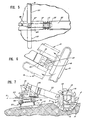
- a modified form of positioning means for the wheel relative to boom end 19 is shown to comprise means 45 for selectively positioning the excavator wheel over a range of approximately 180° to either side of the boom end 19, providing further facilitated flexibility in the use of the excavating apparatus.
- the inclined longitudinal conveyor 36 is fixed on suitable supports 46 to the car bed.
- the hopper- type transverse conveyor 35 is fixedly mounted to receive the material from the movable lower end 34 of boom conveyor 31.
- the discharge, or casting, conveyor 37 is mounted to a swivel 48 rotatably mounted on a support 49 carried on the car bed 24, and is angularly adjustable by means of a piston device 50 so as to permit facilitated control in the discharge of the excavated material therefrom.
- the casting conveyor may be selectively positioned about the vertical axis 47 of the rotatable platform so as to have the distal end 51 of the casting conveyor cantilevered outwardly from either side of the car bed 24, as shown in full and broken lines in Figure 5, or selectively disposed to extend beyond the end of the car bed 24 to overlie a hopper car 52, such as where it is desired to transport the excavated material to a remote site.
- the apparatus is moved along track 11 by powered wheeled trucks generally designated 53.
- the trucks include suitable drive mechanism 54 for driving wheels 55 thereof.
- Suitable hydraulic power for operating the drive mechanism is provided from a suitable travel engine 56 carried on the support bed 24.
- Other hydraulically operated apparatus of the ditcher 10 is powered from a work engine 57, also carried on the support bed 24.
- each of the travel engine 56 and work engine 57 is mounted at the side of the support bed 24 opposite the side from which the boom normally extends so as to act as a counterbalance weight in the operation of the excavator wheel.
- the track 11 is inclined from side to side as at curve portions thereof.
- the invention comprehends provision of means for maintaining the support bed 24 substantially level comprising hydraulically operated supports 58 for adjustably mounting the wheeled trucks 53 to the support bed 24.
- the wheeled trucks may be inclined relative to the flat extent of the support bed 24 so as to cause the support bed to be effectively level, notwithstanding the sideward inclination of the track. It has been found that by maintaining the support bed level at all times, improved operation of the apparatus, including the conveyor belts, is obtained.
- rotation of the excavator wheel has been found to effect a throwing of certain of the excavated material, such as tufts of grass, etc., and by suitably controlling the speed and rotation of the wheel, facilitated disposal thereof may be readily effected.
- the invention further comprehends provision of an operator's cab 59 provided with suitable controls for operating the ditcher apparatus.
- Use of the improved ditcher permits ditching operations to be effected at relatively high speed, such as where the apparatus is moved along the railroad track at speeds of up to approximately 1/10th of a mile per hour.
- Excellent ditching operation has been effected with such apparatus traveling at a speed of approximately .08 mph and excavating wheel having a ring support of approximately 8 feet.
- the invention comprehends an improved ditcher for excavating a ditch alongside a railroad track wherein an excavator wheel is carried on a flatbed railroad car by means of a cantilevered boom.
- the excavator wheel is caused to rotate about a horizontal axis which may be selectively positioned over a range from between extending perpendicular to the longitudinal extent of the track to a position wherein the axis extends substantially parallel thereto.
- a wide range of drainage ditch and the like configurations may be readily effected with minimum manpower and at relatively high speed and efficiency.
- the support bed 24 is provided with a suitable outwardly opening recess 60 for effectively receiving the excavator wheel in a storage position, as shown in broken lines in Figure 2.
- the apparatus is extremely simple and economical of construction and use.
Landscapes
- Engineering & Computer Science (AREA)
- Civil Engineering (AREA)
- Structural Engineering (AREA)
- Mining & Mineral Resources (AREA)
- General Engineering & Computer Science (AREA)
- Mechanical Engineering (AREA)
- Architecture (AREA)
- Excavating Of Shafts Or Tunnels (AREA)
- Crystals, And After-Treatments Of Crystals (AREA)
- Structure Of Belt Conveyors (AREA)
- Soil Working Implements (AREA)
- Machines For Laying And Maintaining Railways (AREA)
- Processing Of Solid Wastes (AREA)
- Paper (AREA)
- Refuge Islands, Traffic Blockers, Or Guard Fence (AREA)
- Road Signs Or Road Markings (AREA)
- Devices Affording Protection Of Roads Or Walls For Sound Insulation (AREA)
- Agricultural Machines (AREA)
Claims (9)
Priority Applications (1)
| Application Number | Priority Date | Filing Date | Title |
|---|---|---|---|
| AT83300332T ATE19116T1 (de) | 1982-01-25 | 1983-01-24 | Verfahren und geraet zum ausheben von graeben. |
Applications Claiming Priority (2)
| Application Number | Priority Date | Filing Date | Title |
|---|---|---|---|
| US06/342,127 US4736534A (en) | 1982-01-25 | 1982-01-25 | Ditcher method and apparatus |
| US342127 | 1982-01-25 |
Publications (2)
| Publication Number | Publication Date |
|---|---|
| EP0086050A1 EP0086050A1 (de) | 1983-08-17 |
| EP0086050B1 true EP0086050B1 (de) | 1986-04-09 |
Family
ID=23340455
Family Applications (1)
| Application Number | Title | Priority Date | Filing Date |
|---|---|---|---|
| EP83300332A Expired EP0086050B1 (de) | 1982-01-25 | 1983-01-24 | Verfahren und Gerät zum Ausheben von Gräben |
Country Status (9)
| Country | Link |
|---|---|
| US (1) | US4736534A (de) |
| EP (1) | EP0086050B1 (de) |
| JP (1) | JPS58146626A (de) |
| AT (1) | ATE19116T1 (de) |
| AU (1) | AU1060483A (de) |
| CA (1) | CA1197864A (de) |
| DE (1) | DE3362851D1 (de) |
| ES (1) | ES519244A0 (de) |
| MX (1) | MX156937A (de) |
Families Citing this family (27)
| Publication number | Priority date | Publication date | Assignee | Title |
|---|---|---|---|---|
| US4713898A (en) * | 1985-12-16 | 1987-12-22 | Loram Maintenance Of Way, Inc. | Railroad mounted trench digger |
| US4784524A (en) * | 1987-04-14 | 1988-11-15 | Henkels & Mccoy, Inc. | Railroad cable laying apparatus with plow blade support and dual plow tethering |
| US5564205A (en) * | 1995-06-01 | 1996-10-15 | Astec Industries, Inc. | Excavating machine with stowable discharge conveyor |
| US5873186A (en) * | 1997-01-13 | 1999-02-23 | Yoder; Shaun Lamar | Excavating machine with cleaning device |
| US6076288A (en) | 1998-04-02 | 2000-06-20 | Ledcor Industries Limited | Method and apparatus for burying cable in a railway bed |
| US6193440B1 (en) * | 1999-02-26 | 2001-02-27 | Kenneth A. Pidgeon | Railroad cable plow apparatus |
| BRPI0518643A2 (pt) * | 2004-12-08 | 2008-12-02 | Shaun L Yoder | mÁquina de escavar para solos rochosos e outros solos |
| CN1928238B (zh) * | 2005-09-09 | 2010-12-22 | 襄樊金鹰轨道车辆有限责任公司 | 一种铁路道岔道碴清筛机(6) |
| US9010261B2 (en) | 2010-02-11 | 2015-04-21 | Allen Szydlowski | Method and system for a towed vessel suitable for transporting liquids |
| US9521858B2 (en) | 2005-10-21 | 2016-12-20 | Allen Szydlowski | Method and system for recovering and preparing glacial water |
| AU2007235680B2 (en) * | 2006-04-10 | 2012-06-07 | Matisa Materiel Industriel Sa | Storage car |
| US7914086B2 (en) * | 2008-10-24 | 2011-03-29 | Deere & Company | Track idler with replaceable wear pads |
| DE102009007224A1 (de) * | 2009-02-03 | 2010-08-05 | Zürcher, Ralf | Verfahren zum Verlegen von U-förmigen Kanalelementen neben dem Gleis einer Bahnstrecke |
| DE102009007222B4 (de) * | 2009-02-03 | 2015-02-12 | Ralf Zürcher | Gleisfahrzeug zum Ausheben eines zu einem Gleis parallelen Grabens bei Bahnstrecken |
| US8375605B2 (en) * | 2009-07-23 | 2013-02-19 | The Charles Machine Works, Inc. | Trenching system |
| US9371114B2 (en) | 2009-10-15 | 2016-06-21 | Allen Szydlowski | Method and system for a towed vessel suitable for transporting liquids |
| US8924311B2 (en) | 2009-10-15 | 2014-12-30 | World's Fresh Waters Pte. Ltd. | Method and system for processing glacial water |
| US9017123B2 (en) | 2009-10-15 | 2015-04-28 | Allen Szydlowski | Method and system for a towed vessel suitable for transporting liquids |
| US11584483B2 (en) | 2010-02-11 | 2023-02-21 | Allen Szydlowski | System for a very large bag (VLB) for transporting liquids powered by solar arrays |
| US10024459B1 (en) * | 2015-04-02 | 2018-07-17 | Ag Leader Technology, Inc. | Tile feed wheel control |
| US10813281B2 (en) | 2018-02-20 | 2020-10-27 | Ag Leader Technology | Apparatus, systems and methods for applying fluid |
| CN109972605A (zh) * | 2019-05-13 | 2019-07-05 | 四川农业大学 | 高原固沙沙沟挖掘装置 |
| CN111535088B (zh) * | 2020-06-15 | 2024-05-28 | 金鹰重型工程机械股份有限公司 | 一种道砟挖掘装置及道岔清筛机 |
| CN113073695A (zh) * | 2021-04-12 | 2021-07-06 | 陈敬锋 | 一种农业灌溉v型排水渠开槽装置 |
| CN113529839B (zh) * | 2021-08-13 | 2022-07-26 | 中国水电基础局有限公司 | 一种双轮铣槽机的安装方法 |
| MX2022010802A (es) | 2021-10-15 | 2023-04-17 | Herzog Railroad Services Inc | Accesorio de zanjeo rotativo para un brazo manipulador de herramienta. |
| CN119466070B (zh) * | 2025-01-16 | 2025-03-25 | 中国水利水电第九工程局有限公司 | 一种太阳能光伏发电施工用挖沟装置 |
Family Cites Families (14)
| Publication number | Priority date | Publication date | Assignee | Title |
|---|---|---|---|---|
| US1216779A (en) * | 1913-03-12 | 1917-02-20 | William J Dankel | Grader or excavating-machine. |
| US1864552A (en) * | 1929-03-07 | 1932-06-28 | O F Jordan Co | Excavator car |
| US2196880A (en) * | 1938-01-03 | 1940-04-09 | Buckeye Traction Ditcher Co | Ballast cleaning machine |
| GB767302A (en) * | 1954-01-13 | 1957-01-30 | British Insulated Callenders | An improved excavator |
| US3683522A (en) * | 1970-04-13 | 1972-08-15 | Louis Rousseau | Frustoconical rotary cutter for digging trenches |
| FR2046674A5 (de) * | 1970-05-25 | 1971-03-05 | Inst Zheleznodorozhn | |
| US3841254A (en) * | 1972-01-31 | 1974-10-15 | G Dragonas | Vessel with removable sections |
| US3967396A (en) * | 1974-09-23 | 1976-07-06 | Canron, Inc. | Undercutter with rotary trencher |
| DE2522562A1 (de) * | 1975-05-22 | 1976-12-09 | Koch Transporttechnik Gmbh | Schaufelradbagger mit in beiden drehrichtungen antreibbarem schaufelrad |
| US4106226A (en) * | 1977-02-18 | 1978-08-15 | Hanson Raymond A | Bidirectional rotary excavator |
| US4120106A (en) * | 1977-04-14 | 1978-10-17 | Cmi Corporation | Sidebank excavator with rotating vertical cutter assembly |
| US4203493A (en) * | 1978-11-21 | 1980-05-20 | Southern Railway Company | Railway ballast cleaning apparatus |
| DD145294A1 (de) * | 1979-08-08 | 1980-12-03 | Rolf Rueger | Schaufelrad |
| GB2081345B (en) * | 1980-07-22 | 1984-04-11 | Drg Uk Ltd | Bucket wheels and bucket wheel reclaimers |
-
1982
- 1982-01-25 US US06/342,127 patent/US4736534A/en not_active Expired - Fee Related
-
1983
- 1983-01-19 AU AU10604/83A patent/AU1060483A/en not_active Abandoned
- 1983-01-24 EP EP83300332A patent/EP0086050B1/de not_active Expired
- 1983-01-24 AT AT83300332T patent/ATE19116T1/de not_active IP Right Cessation
- 1983-01-24 DE DE8383300332T patent/DE3362851D1/de not_active Expired
- 1983-01-25 ES ES519244A patent/ES519244A0/es active Granted
- 1983-01-25 CA CA000420234A patent/CA1197864A/en not_active Expired
- 1983-01-25 JP JP58010462A patent/JPS58146626A/ja active Pending
- 1983-01-25 MX MX196024A patent/MX156937A/es unknown
Also Published As
| Publication number | Publication date |
|---|---|
| DE3362851D1 (en) | 1986-05-15 |
| US4736534A (en) | 1988-04-12 |
| ATE19116T1 (de) | 1986-04-15 |
| ES8405467A1 (es) | 1984-06-01 |
| AU1060483A (en) | 1983-08-04 |
| MX156937A (es) | 1988-10-17 |
| ES519244A0 (es) | 1984-06-01 |
| JPS58146626A (ja) | 1983-09-01 |
| CA1197864A (en) | 1985-12-10 |
| EP0086050A1 (de) | 1983-08-17 |
Similar Documents
| Publication | Publication Date | Title |
|---|---|---|
| EP0086050B1 (de) | Verfahren und Gerät zum Ausheben von Gräben | |
| US4563826A (en) | Apparatus for removing ballast from beneath a railroad track | |
| CA1093387A (en) | Method for removing ballast from railroad tracks | |
| US3967396A (en) | Undercutter with rotary trencher | |
| US4713898A (en) | Railroad mounted trench digger | |
| JP4713016B2 (ja) | 旧軌道を除去し、新軌道を敷設する機械およびその方法 | |
| US6591971B1 (en) | Silage mover | |
| US4088236A (en) | Multiple use earth working machine | |
| CN1098398C (zh) | 挖掘道床材料用的线路施工机械 | |
| US4674208A (en) | Ballast removing apparatus | |
| US4152991A (en) | Ripping apparatus | |
| CN1174916A (zh) | 挖掘轨道道床材料用的线路施工机械 | |
| CN206118407U (zh) | 一种山药收获机 | |
| EP0283286A2 (de) | Vorrichtung zum Entfernen einer Schicht an der Bodenoberfläche | |
| US3392464A (en) | Road widening trencher-loader unit | |
| US4400897A (en) | Method and railway train for draining a railway track | |
| CN1210177A (zh) | 收取放置在轨道上的散装物料用的机械 | |
| EP1348057B1 (de) | Vorrichtung und verfahren zur entfernung von schotterbettung | |
| AU605411B2 (en) | Improved continuous excavating apparatus and method | |
| EP0052089B1 (de) | Vorrichtung zur maschinellen Handhabung von Material auf Eisenbahndämmen, insbesondere zur Handhabung von Schotter | |
| RU2376409C1 (ru) | Путевая машина | |
| RU2092645C1 (ru) | Устройство для выемки балласта железнодорожного пути | |
| SK500442016U1 (sk) | Zariadenie na úpravu a tvarovanie železničného zvršku, bočných strán železničných priekop a úpravy koľajového lôžka | |
| RU2839787C1 (ru) | Щебнеочистительная машина | |
| CN223373524U (zh) | 一种筛分机 |
Legal Events
| Date | Code | Title | Description |
|---|---|---|---|
| PUAI | Public reference made under article 153(3) epc to a published international application that has entered the european phase |
Free format text: ORIGINAL CODE: 0009012 |
|
| AK | Designated contracting states |
Designated state(s): AT BE CH DE FR GB IT LI LU NL SE |
|
| 17P | Request for examination filed |
Effective date: 19840213 |
|
| ITF | It: translation for a ep patent filed | ||
| GRAA | (expected) grant |
Free format text: ORIGINAL CODE: 0009210 |
|
| AK | Designated contracting states |
Kind code of ref document: B1 Designated state(s): AT BE CH DE FR GB IT LI LU NL SE |
|
| PG25 | Lapsed in a contracting state [announced via postgrant information from national office to epo] |
Ref country code: NL Effective date: 19860409 Ref country code: LI Effective date: 19860409 Ref country code: CH Effective date: 19860409 Ref country code: BE Effective date: 19860409 |
|
| REF | Corresponds to: |
Ref document number: 19116 Country of ref document: AT Date of ref document: 19860415 Kind code of ref document: T |
|
| PG25 | Lapsed in a contracting state [announced via postgrant information from national office to epo] |
Ref country code: SE Effective date: 19860430 |
|
| ET | Fr: translation filed | ||
| REF | Corresponds to: |
Ref document number: 3362851 Country of ref document: DE Date of ref document: 19860515 |
|
| REG | Reference to a national code |
Ref country code: CH Ref legal event code: PL |
|
| NLV1 | Nl: lapsed or annulled due to failure to fulfill the requirements of art. 29p and 29m of the patents act | ||
| PGFP | Annual fee paid to national office [announced via postgrant information from national office to epo] |
Ref country code: AT Payment date: 19861217 Year of fee payment: 5 |
|
| PG25 | Lapsed in a contracting state [announced via postgrant information from national office to epo] |
Ref country code: LU Free format text: LAPSE BECAUSE OF NON-PAYMENT OF DUE FEES Effective date: 19870131 |
|
| PLBE | No opposition filed within time limit |
Free format text: ORIGINAL CODE: 0009261 |
|
| STAA | Information on the status of an ep patent application or granted ep patent |
Free format text: STATUS: NO OPPOSITION FILED WITHIN TIME LIMIT |
|
| 26N | No opposition filed | ||
| PG25 | Lapsed in a contracting state [announced via postgrant information from national office to epo] |
Ref country code: AT Effective date: 19880124 |
|
| GBPC | Gb: european patent ceased through non-payment of renewal fee | ||
| PG25 | Lapsed in a contracting state [announced via postgrant information from national office to epo] |
Ref country code: FR Free format text: LAPSE BECAUSE OF NON-PAYMENT OF DUE FEES Effective date: 19880930 |
|
| PG25 | Lapsed in a contracting state [announced via postgrant information from national office to epo] |
Ref country code: DE Effective date: 19881001 |
|
| PG25 | Lapsed in a contracting state [announced via postgrant information from national office to epo] |
Ref country code: GB Free format text: LAPSE BECAUSE OF NON-PAYMENT OF DUE FEES Effective date: 19881122 |
|
| REG | Reference to a national code |
Ref country code: FR Ref legal event code: ST |