EP0086082A2 - Ratchet and tools incorporating a ratchet - Google Patents
Ratchet and tools incorporating a ratchet Download PDFInfo
- Publication number
- EP0086082A2 EP0086082A2 EP83300535A EP83300535A EP0086082A2 EP 0086082 A2 EP0086082 A2 EP 0086082A2 EP 83300535 A EP83300535 A EP 83300535A EP 83300535 A EP83300535 A EP 83300535A EP 0086082 A2 EP0086082 A2 EP 0086082A2
- Authority
- EP
- European Patent Office
- Prior art keywords
- ramps
- torque
- ratchet
- discs
- series
- Prior art date
- Legal status (The legal status is an assumption and is not a legal conclusion. Google has not performed a legal analysis and makes no representation as to the accuracy of the status listed.)
- Withdrawn
Links
Images


Classifications
-
- B—PERFORMING OPERATIONS; TRANSPORTING
- B25—HAND TOOLS; PORTABLE POWER-DRIVEN TOOLS; MANIPULATORS
- B25B—TOOLS OR BENCH DEVICES NOT OTHERWISE PROVIDED FOR, FOR FASTENING, CONNECTING, DISENGAGING, OR HOLDING
- B25B23/00—Details of, or accessories for, spanners, wrenches, screwdrivers
- B25B23/14—Arrangement of torque limiters or torque indicators in wrenches or screwdrivers
- B25B23/141—Mechanical overload release couplings
-
- B—PERFORMING OPERATIONS; TRANSPORTING
- B25—HAND TOOLS; PORTABLE POWER-DRIVEN TOOLS; MANIPULATORS
- B25B—TOOLS OR BENCH DEVICES NOT OTHERWISE PROVIDED FOR, FOR FASTENING, CONNECTING, DISENGAGING, OR HOLDING
- B25B13/00—Spanners; Wrenches
- B25B13/46—Spanners; Wrenches of the ratchet type, for providing a free return stroke of the handle
- B25B13/461—Spanners; Wrenches of the ratchet type, for providing a free return stroke of the handle with concentric driving and driven member
- B25B13/466—Spanners; Wrenches of the ratchet type, for providing a free return stroke of the handle with concentric driving and driven member the ratchet parts engaging in an axial direction
-
- B—PERFORMING OPERATIONS; TRANSPORTING
- B25—HAND TOOLS; PORTABLE POWER-DRIVEN TOOLS; MANIPULATORS
- B25B—TOOLS OR BENCH DEVICES NOT OTHERWISE PROVIDED FOR, FOR FASTENING, CONNECTING, DISENGAGING, OR HOLDING
- B25B13/00—Spanners; Wrenches
- B25B13/46—Spanners; Wrenches of the ratchet type, for providing a free return stroke of the handle
- B25B13/461—Spanners; Wrenches of the ratchet type, for providing a free return stroke of the handle with concentric driving and driven member
- B25B13/467—Spanners; Wrenches of the ratchet type, for providing a free return stroke of the handle with concentric driving and driven member which are gear-operated
-
- B—PERFORMING OPERATIONS; TRANSPORTING
- B25—HAND TOOLS; PORTABLE POWER-DRIVEN TOOLS; MANIPULATORS
- B25B—TOOLS OR BENCH DEVICES NOT OTHERWISE PROVIDED FOR, FOR FASTENING, CONNECTING, DISENGAGING, OR HOLDING
- B25B23/00—Details of, or accessories for, spanners, wrenches, screwdrivers
- B25B23/14—Arrangement of torque limiters or torque indicators in wrenches or screwdrivers
- B25B23/142—Arrangement of torque limiters or torque indicators in wrenches or screwdrivers specially adapted for hand operated wrenches or screwdrivers
Definitions
- This invention relates to ratchets with torque- limiting characteristics and tools incorporating such ratchets.
- a torque limiting ratchet comprising a pair of discs arranged face-to-face and loaded together by a spring up to a predetermined limit, the discs each having a series of pressed-out ramps terminating in shoulders, with the ramps of each series facing the same way and being in opposition to the ramps of the other series so that when rotating in the loosening direction the torque is transmitted via the shoulders, and when rotating in the tightening direction the torque is transmitted via the faces of the ramps up to the required limit imposed by the spring loading.
- a spark plug spanner including a torque limiting ratchet comprising a pair of discs arranged face-to-face and spring loaded together, the discs each having a series of pressed-out ramps terminating in shoulders, with the ramps of each series facing the same way and beingin opposition to the ramps of the other series so that when rotating in the loosening direction the torque is transmitted via the shoulders, and when rotating in the tightening direction the torque is transmitted-via the faces of the ramps up to the limit imposed by the spring.loading.
- a spark plug spanner including a first body portion to be turned by the user, a second body portion to turn a plug and a torque limiting ratchet comprising a pair of discs arranged face-to-face and spring loaded together, one of the discs being attached to each of the first and second body portions, the discs each having a series of pressed-out ramps terminating in shoulders, with the ramps of each series facing the same way and being in opposition to the ramps of the other series so that when rotating in the loosening direction the torque is transmitted via the shoulders, and when rotating in the tightening direction the torque is transmitted via the faces of the ramps up to the limit imposed by the spring.loading.
- Mot6r'vehicle wheel nuts should be tightened to a standard specified torque.
- wheel nuts it is not uncommon for wheel nuts to be overtightened by the use of excessive torque which not only may damage the threads on the studs and/or nuts, but also creates considerable difficulties in subsequent loosening. This circumstance has led to a widespread feeling, particularly among women drivers, that changing a wheel is physically difficult as it may involve, using standard tools, the use of greater force than they can apply.
- a wheel brace providing mechanical advantage by the use of gearing but incorporating a form of torque limiting ratchet to prevent overtightening.
- a wheel brace has to be inexpensive and compact enough to be carried in the vehicle as part of a tool kit.
- a wheel brace comprising an epicyclic gear set including a sun gear, a ring gear and one or more planetary gears meshing with the sun and ring gears and mounted in a cage, means for restraining movement of one of the ring gear and cage, means for connecting a socket to the other of the ring gear and cage, means for manually rotating the sun gear so as to turn the socket at a reduced speed with mechanical advantage and a torque limiting device operable to limit the torque in one direction of rotation of the socket, in which the torque limiting device comprises a pair of discs arranged face-to-face and spring loaded together, the discs each having a series of ramps, with the ramps of each series in opposition so that the torque is transmitted through the faces of the ramps in at least one direction up to a limit determined by the shape of the ramps and the spring loading.
- the restraining means may be an arm, e.g. of adjustable effective length, having means to engage a wheel nut or the wheel rim.
- the gears may be stamped from sheet metal.
- the discs may each have a series of pressed-out ramps.
- the shoulders may be somewhat inclined so that there is a torque limit in both directions.
- the wheel brace illustrated in Figure 1 includes a standard socket 1 adapted in engage on the wheel nut to be loosened or tightened, and it is driven by means of a handle or tommy bar 2 engaged in aligned holes 3 in a tube 4.
- the handle or tomry bar 2 may be separate or welded in position in the icles 3.
- the tube 4 is welded to a first ratchet disc 5 which is in face-to-face relationship with a second ratchet disc 6, as shown in Figure 3.
- a pin 7 passes axially through both ratchet discs, with its head 7a against the disc 6, and carries a spring abutment plate 8 so that when assembled a spring 9 is compressed between the plate 8 and the rear of the ratchet plate 5 so as to spring load the ratchet plates together.
- the ratchet plates 5 and 6 are formed with ramps 5a, 6a upset.from the metal of the disc in the peripheral region thereof, so as to provide each ratchet disc with a series of similarly facing ramps terminating in shoulders 5b, 6b respectively.
- the ramps are in opposition on the two ratchet discs so that when the tube 4 and ratchet disc 5 are rotated in one direction, the shoulders 5b and 6b come into engagement, as shown in Figure 3, and transmit the full torque to the ratchet plate 6.
- the ratchet disc 5 rotates somewhat until the faces of the ramps 5a are in engagement with the faces of the ramps 6a, and torque is transmitted through these faces.
- a sun gear 11 forming part of an epicyclic system illustrated in Figure 2.
- the sun gear 11 is in mesh with three planetary gears 12 which are themselves attached to a cage formed by front and rear plates 13 and 14 respectively. Rivets for this purpose are shown at 15.
- a normally stationary ring gear 16 is formed on the interior of a dished ring 17.
- the dished ring 17 is formed with a radial extension 18'(omitted from Figure 2) which forms part of a restraining arm assembly.
- the extension 18 is formed with a slot 19 and a second slotted arm 21 is attached to the extension 18 by means of a nut 22 and bolt 23 passing through the slot 19 and a slot 24 in the arm portion 21.
- the arm portion 21 itself carries a short length of tube 25 adapted to engage over a wheel nut adjacent that engaged by the socket 1 to provide anchorage for the dished ring 17 and its gear 16.
- the position of the arm portion 21 can be adjusted by means of the slots 19 and 24 retained in the adjusted position by the nut and bolt.
- the arm portion 21 may be reversed as shown in Figures 4a and 4b from which the nut and bolt 22 and 23 have been omitted.
- a holder 27 which is adapted to receive the socket 1.
- a range of standard sockets 1 may be provided for attachment to the single holder 27, e.g. by means of grub screws or similar fixings.
- the position of the tube length 25 is first adjusted to suit the wheel on which the wheel brace is to be used, and then with the socket 1 over the nut to be loosened or tightened, and the tube length over an adjacent nut, the tommy bar or handle 2 is rotated in the appropriate direction.
- the full torque applied is transmitted through the shoulders 5a and 6b of the ratchet, and in the opposite direction to tighten the nuts, the torque limiting feature of the ratchet comes into play and the torque required is transmitted through the faces of the ramps 5a and 6a.
- the sun gear 11 is in mesh with the planet gears 12 and these in turn are in mesh with the ring gear 16 so that the planetary gears 12 precess and the cage formed by the plates 13 and 14 thus rotates at a reduced speed.
- the speed reduction is in the region of 10 to 1.
- the socket 1 which is solid with the plate 13 is thus rotated more slowly and a comparatively small torque applied to the handle or tommy bar 2 will apply substantial torque to the nut to which the socket 1 is connected.
- the amount of actual physical strength required for loosening and tightening wheel nuts is significantly reduced.
- Figures 5 and 6 show a form of wheel brace incorporating some modifications.
- the gearing is basically the same and needs no further description, but the ratchet is slightly modified, so that instead of two shoulders 6b and 5b meshing in the loosening direction, contact is between steeply inclined ramps 5c and 6c to permit the ratchet to slip in the loosening direction if the torque exceeds a given high level.
- the purpose of this is to protect the gears from damage due to misuse of the wheel brace in situations for which it is not designed.
- the arm portion 21a may be made somewhat longer and provided with a pad 26 of hard rubber or similar material to engage on an appropriate portion of a wheel rim.
- the extension18a is shown in Figure 6 as being inclined to the plane of the ring 17, and the arm 21a is shown as having two fixing holes 27a and 27b, at different angles to enable the arm to be more steeply inclined to the plane of the dished ring 17 when in the shorter position.
- Each hole 27a and 27b is also associated with an adjacent upset locating lug 28a, 28b cooperating with the slot 19 in the exterior 18a.
- the tube 4 may be separable from the ratchet disc 5.
- it may be provided with a socket end to receive a spigot, e..g. hexagonal or square, solid with the disc 5.
- the plug spanner illustrated has a conventional hexagonal socket 121 at the outer end of a tubular body member 122, and at the opposite end, a tubular body member 123 is provided with a stirrup 124 pivotally received in appropriate holes near the end of the tubular member 123.
- tubular body elements 122 and 123 are part of a single tube, but in accordance with the present invention, the tubular body members 122 and 123 are each attached, e.g. by welds 125 to a respective ratchet disc 126 or 127.
- the tube 122 is welded to a first ratchet disc 126 which is in face-to-face relationship with the second ratchet disc 127 to which the tube 123 is welded, as shown in Figure 4.
- a pin 128 passes axially through both ratchet discs 126 and 127, with its head 128a against the disc 126, and is peened over a spring abutment plate 129 so that, when assembled, a spring 130 is compressed between the plate 129 and the rear of the ratchet disc 127 so as to spring load the ratchet discs 126 and 127 together.
- the ratchet discs 126 and 127 are each formed with a plurality of equi-spaced ramps 126a and 127a upset from the metal of the disc in the peripheral region thereof, so as to provide each ratchet disc with a series of similarly facing ramps terminating in shoulders (or more steeply inclined ramps) 126b and 127b respectively.
- the ramps are in opposition on the two ratchet discs so that when the tubular member 123 and ratchet disc 127 are rotated in one direction, the shoulders 126b and 127b come into engagement and transmit the full torque (or up to a very high torque) to the ratchet plate 126.
- the ratchet disc 127 When rotated in the opposite direction, the ratchet disc 127 rotates somewhat until the faces of the ramps 127a are in engagement with the faces of the ramps 126a, and torque is transmitted through these faces. Should the torque become excessive, the ramps 126a will ride over the ramps 127a and the ramps will be forced apart against the action of the spring 129, so that the ratchet mechanism will slip round.
- the actual limiting torque will depend upon the angles of the ramps 126a and 127a and on the characteristics of the spring, including the amount of initial compression applied to it in the initial position shown in Figure 4.
- the plug spanner is shown as including a rubber or like soft insert 131 which lightly grips a plug over which the spanner has been introduced so that the spanner may also be used to lift the plug clear of the engine and also to introduce the plug into the engine when required.
Landscapes
- Engineering & Computer Science (AREA)
- Mechanical Engineering (AREA)
- Details Of Spanners, Wrenches, And Screw Drivers And Accessories (AREA)
- Mechanical Operated Clutches (AREA)
- Transmission Devices (AREA)
Abstract
In order to provide a ratchet which can be made from inexpensive parts, it comprises a pair of discs (5 and 6) having ramps (5a, 6a) upset from a peripheral zone of the discs and terminating in shoulders (5b, 6b). The discs are loaded together by a spring 9 which enables the drive to be transmitted via the faces of the ramps (5 and 6) up to a predetermined limit before the discs separate and the ratchet clicks over. In the opposite direction the drive is transmitted through the shoulders (5b, 6b), which may then be inclined to provide a torque limitation. The ratchet may for example be used in wheel braces (as illustrated in Figure 1) or in spark plug spanners.
Description
- This invention relates to ratchets with torque- limiting characteristics and tools incorporating such ratchets.
- In a number of engineering applications, e.g. wheel braces or spark plug spanners, it is required to transmit a high torque, e.g. all the available torque, in one direction of rotation, while being able to limit the torque transmitted in the opposite direction e.g. to prevent over tightening.
- Mechanisms for performing this function are already known, but normally comprise expensive components.
- It is an object of the invention to provide a torque limiting ratchet which may be manufactured reasonably inexpensively.
- In accordance with the invention, there is provided a torque limiting ratchet comprising a pair of discs arranged face-to-face and loaded together by a spring up to a predetermined limit, the discs each having a series of pressed-out ramps terminating in shoulders, with the ramps of each series facing the same way and being in opposition to the ramps of the other series so that when rotating in the loosening direction the torque is transmitted via the shoulders, and when rotating in the tightening direction the torque is transmitted via the faces of the ramps up to the required limit imposed by the spring loading.
- It has previously been proposed, for example in published United Kingdom patent application 2062524, to provide a spark plug spanner with a torque limiting ratchet. However, the constructions proposed have necessitated interengaging sets of teeth and as such, the precision of the engineering required has meant that the cost is too great for the device to obtain ready acceptance. Also, the torque limiting ratchet is not built into the spanner as such but has to be attached thereto.
- In accordance with another aspect of the present invention, there is provided a spark plug spanner including a torque limiting ratchet comprising a pair of discs arranged face-to-face and spring loaded together, the discs each having a series of pressed-out ramps terminating in shoulders, with the ramps of each series facing the same way and beingin opposition to the ramps of the other series so that when rotating in the loosening direction the torque is transmitted via the shoulders, and when rotating in the tightening direction the torque is transmitted-via the faces of the ramps up to the limit imposed by the spring.loading.
- In accordance with a further aspect of the present invention, there is provided a spark plug spanner including a first body portion to be turned by the user, a second body portion to turn a plug and a torque limiting ratchet comprising a pair of discs arranged face-to-face and spring loaded together, one of the discs being attached to each of the first and second body portions, the discs each having a series of pressed-out ramps terminating in shoulders, with the ramps of each series facing the same way and being in opposition to the ramps of the other series so that when rotating in the loosening direction the torque is transmitted via the shoulders, and when rotating in the tightening direction the torque is transmitted via the faces of the ramps up to the limit imposed by the spring.loading.
- Mot6r'vehicle wheel nuts should be tightened to a standard specified torque. However, it is not uncommon for wheel nuts to be overtightened by the use of excessive torque which not only may damage the threads on the studs and/or nuts, but also creates considerable difficulties in subsequent loosening. This circumstance has led to a widespread feeling, particularly among women drivers, that changing a wheel is physically difficult as it may involve, using standard tools, the use of greater force than they can apply.
- In order to overcome this, it is proposed to provide a wheel brace providing mechanical advantage by the use of gearing but incorporating a form of torque limiting ratchet to prevent overtightening. In order to be economic, such a wheel brace has to be inexpensive and compact enough to be carried in the vehicle as part of a tool kit.
- Its use is comparatively infrequent so it does not need to be particularly durable.
- In accordance with a further aspect of the present invention, there is provided a wheel brace comprising an epicyclic gear set including a sun gear, a ring gear and one or more planetary gears meshing with the sun and ring gears and mounted in a cage, means for restraining movement of one of the ring gear and cage, means for connecting a socket to the other of the ring gear and cage, means for manually rotating the sun gear so as to turn the socket at a reduced speed with mechanical advantage and a torque limiting device operable to limit the torque in one direction of rotation of the socket, in which the torque limiting device comprises a pair of discs arranged face-to-face and spring loaded together, the discs each having a series of ramps, with the ramps of each series in opposition so that the torque is transmitted through the faces of the ramps in at least one direction up to a limit determined by the shape of the ramps and the spring loading.
- The restraining means may be an arm, e.g. of adjustable effective length, having means to engage a wheel nut or the wheel rim.
- The gears may be stamped from sheet metal.
- The discs may each have a series of pressed-out ramps.
- In all cases the shoulders may be somewhat inclined so that there is a torque limit in both directions.
- The invention will be further described with reference to the accompanying drwings of which:-
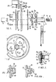
- Figure 1 is an exploded view of a wheel brace incorporating a ratchet devize in accordance with a preferred embodiment of the invention;
- Figure 2 is an end elevation of the gear train;
- Figure 3 is a sections view showing the assembly of parts of a torque limiting device;
- Figures 4a and 4b shot alternative positions of a restraining part;
- Figure 5 is a front elevation of a modified form of wheel brace;
- Figure 6 is a side elevation of the wheel brace of Figure 5;
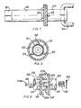
- Figure 7 is a side elevation of a spark plug spanner including a ratchet in accordance with one form of the invention;
- Figure 8 is an end elevation of the spanner of Figure 7; and
- Figure 9 is an exploded view of the ratchet device shown in Figure 7.
- The wheel brace illustrated in Figure 1 includes a
standard socket 1 adapted in engage on the wheel nut to be loosened or tightened, and it is driven by means of a handle ortommy bar 2 engaged in alignedholes 3 in atube 4. The handle ortomry bar 2 may be separate or welded in position in theicles 3. Thetube 4 is welded to afirst ratchet disc 5 which is in face-to-face relationship with asecond ratchet disc 6, as shown in Figure 3. Apin 7 passes axially through both ratchet discs, with its head 7a against thedisc 6, and carries aspring abutment plate 8 so that when assembled aspring 9 is compressed between theplate 8 and the rear of theratchet plate 5 so as to spring load the ratchet plates together. - The
ratchet plates ramps shoulders tube 4 andratchet disc 5 are rotated in one direction, theshoulders ratchet plate 6. When rotated in the opposite direction, theratchet disc 5 rotates somewhat until the faces of theramps 5a are in engagement with the faces of theramps 6a, and torque is transmitted through these faces. Should the torque become excessive, theramps 6a will be forced, against the action of thespring 9, in an axial direction away from thedisc 5 and the ratchet mechanism will slip round. The actual limiting torque will depend upon the angles of theramps - Attached to the
ratchet plate 6, e.g. by welding, is asun gear 11 forming part of an epicyclic system illustrated in Figure 2. Thesun gear 11 is in mesh with threeplanetary gears 12 which are themselves attached to a cage formed by front andrear plates stationary ring gear 16 is formed on the interior of a dishedring 17. - The dished
ring 17 is formed with a radial extension 18'(omitted from Figure 2) which forms part of a restraining arm assembly. Theextension 18 is formed with aslot 19 and a second slottedarm 21 is attached to theextension 18 by means of anut 22 andbolt 23 passing through theslot 19 and aslot 24 in thearm portion 21. Thearm portion 21 itself carries a short length oftube 25 adapted to engage over a wheel nut adjacent that engaged by thesocket 1 to provide anchorage for the dishedring 17 and itsgear 16. - In order to make the relative positions of the
tube 25 andsocket 1 adjustable for different sizes of wheels, the position of thearm portion 21 can be adjusted by means of theslots arm portion 21 may be reversed as shown in Figures 4a and 4b from which the nut andbolt - Welded to the centre of the
plate 13, forming part of the cage for theplanetary gears 12, is a holder 27 which is adapted to receive thesocket 1. If desired, a range ofstandard sockets 1 may be provided for attachment to the single holder 27, e.g. by means of grub screws or similar fixings. - In operation, the position of the
tube length 25 is first adjusted to suit the wheel on which the wheel brace is to be used, and then with thesocket 1 over the nut to be loosened or tightened, and the tube length over an adjacent nut, the tommy bar orhandle 2 is rotated in the appropriate direction. In the direction to loosen the nuts, the full torque applied is transmitted through theshoulders ramps sun gear 11 is in mesh with theplanet gears 12 and these in turn are in mesh with thering gear 16 so that theplanetary gears 12 precess and the cage formed by theplates socket 1 which is solid with theplate 13 is thus rotated more slowly and a comparatively small torque applied to the handle ortommy bar 2 will apply substantial torque to the nut to which thesocket 1 is connected. Thus the amount of actual physical strength required for loosening and tightening wheel nuts is significantly reduced. - Figures 5 and 6 show a form of wheel brace incorporating some modifications. The gearing is basically the same and needs no further description, but the ratchet is slightly modified, so that instead of two
shoulders inclined ramps arm portion 21a may be made somewhat longer and provided with apad 26 of hard rubber or similar material to engage on an appropriate portion of a wheel rim. In order to provide for different wheel configurations, the extension18a is shown in Figure 6 as being inclined to the plane of thering 17, and thearm 21a is shown as having twofixing holes ring 17 when in the shorter position. Eachhole upset locating lug 28a, 28b cooperating with theslot 19 in theexterior 18a. - Also, the
tube 4 may be separable from theratchet disc 5. For instance, it may be provided with a socket end to receive a spigot, e..g. hexagonal or square, solid with thedisc 5. - Turning now to Figures 7, 8 and 9, the plug spanner illustrated has a conventional
hexagonal socket 121 at the outer end of atubular body member 122, and at the opposite end, atubular body member 123 is provided with astirrup 124 pivotally received in appropriate holes near the end of thetubular member 123. - In a conventional plug spanner, the
tubular body elements tubular body members welds 125 to arespective ratchet disc - As shown more particularly in Figure 9, the
tube 122 is welded to afirst ratchet disc 126 which is in face-to-face relationship with thesecond ratchet disc 127 to which thetube 123 is welded, as shown in Figure 4. Apin 128 passes axially through bothratchet discs head 128a against thedisc 126, and is peened over aspring abutment plate 129 so that, when assembled, aspring 130 is compressed between theplate 129 and the rear of theratchet disc 127 so as to spring load theratchet discs - The
ratchet discs ramps tubular member 123 and ratchetdisc 127 are rotated in one direction, theshoulders ratchet plate 126. When rotated in the opposite direction, theratchet disc 127 rotates somewhat until the faces of theramps 127a are in engagement with the faces of theramps 126a, and torque is transmitted through these faces. Should the torque become excessive, theramps 126a will ride over theramps 127a and the ramps will be forced apart against the action of thespring 129, so that the ratchet mechanism will slip round. The actual limiting torque will depend upon the angles of theramps - It will be seen from Figure 2 that the plug spanner is shown as including a rubber or like
soft insert 131 which lightly grips a plug over which the spanner has been introduced so that the spanner may also be used to lift the plug clear of the engine and also to introduce the plug into the engine when required. - Various modifications may be made within the scope of the invention.
Claims (12)
1. A torque limiting ratchet comprising a pair of discs (5, 6 or 126, 127) arranged face-to-face and loaded together by a spring (7 or 130) up to a predetermined limit, characterised in that the discs (5, 6, 126, 127) each have a series of pressed-out ramps (5a, 6a, 126a, 127a) terminating in shoulders (5b, 6b, 126b, 127b), the ramps of each series facing the same way and being in opposition to the ramps of the other series so that when rotating on the loosening direction the torque is transmitted via the shoulders (5b, 6b or 126b, 127b), and when rotating in the tightening direction the torque is transmitted via the faces of the ramps (5a, 6a or 126a, 127a) up to the required limit imposed by spring loading.
2. A ratchet according to claim 1, characterised in that the ramps (5a, 6a, 126a, 127a) are upset from a peripheral zone of the respective discs (5, 6, 126, 127).
3. A ratchet according to claim 1 or 2, characterised in that a driving tube (4, 122) for one plate (5, 126) acts as a housing for the spring (7, 130) loading the plates (5, 6 or 126, 127) together.
4. A ratchet according to claim 1, 2 or 3, characterised in that the shoulders are formed by ramps (5c, 6c) more steeply inclined than the first mentioned ramps (5a, 6a) so as to present a torque limitation in the loosening direction.
5. A spark plug spanner including a torque limiting ratchet, characterised in that the ratchet comprises a pair of discs (5, 6 or 126, 127) arranged face-to-face and spring loaded together, the discs (5, 6, 126, 127) each having a series of pressed-out ramps (5a, 6a, 126a, 127a) terminating in shoulders (5b, 6b, 126b, 127b), with the ramps of each series facing the same way and being in opposition to the ramps of the other series so that when rotating in the loosening direction the torque is transmitted via the shoulders (5b, 6b, 126b, 127b), and when rotating in the tightening direction the torque is transmitted via the faces of the ramps (5a, 6a, 126a, 127a) up to the limit imposed by the spring loading.
6. A spark plug spanner according to claim 5, in which the shoulders are formed by ramps more steeply inclined than the first mentioned ramps so as to present a torque limitation in the loosening direction.
7. A spark plug spanner characterised by including a first body portion (123) to be turned by the user, a second body portion (122) to turn a plug and a torque limiting ratchet comprising a pair of discs (126, 127) arranged face-to-face and spring loaded together, one of the discs being attached to each of the first and second body portions (123, 122), the discs (126, 127) each having a series of pressed-out ramps (126a, 127a) terminating in shoulders (126b, 127b), with the ramps of each series facing the same way and being in opposition to the ramps of the other series so that when rotating in the loosening direction the torque is transmitted via the shoulders (126b, 127b), and when rotating in the tightening direction the torque is transmitted via the faces of the ramps (126a, 127a) up to the limit imposed by the spring loading.
8. A spark plug spanner according to claim 8, characterised in that which the shoulders (126b, 127b) are formed by ramps more steeply inclined than the first mentioned ramps (126a, 127a) so as to present a torque limitation in the loosening direction.
9. A wheel brace comprising an epicyclic gear set including a sun gear (11) , a ring gear (16) and one or more planetary gears (12) meshing with the sun and ring gears and mounted in a cage (13, 14), means (25, 26) for restraining movement of one of the ring gear (16) and cage (13, 14) means (27) for connecting a socket (1) to the other of the ring gear (16) and cage (13, 14), means (2) for manually rotating the sun gear (11) so as to turn the socket (1) at a reduced speed with mechancial advantage, and a torque limiting device operable to limit the torque in one direction of rotation of the socket (1), characterised in that the torque limiting device comprises a pair of discs (5, 6) arranged face-to-face and spring loaded together, the discs (5, 6) each having a series of ramps (5a, 6a) with the ramps of each series in opposition so that the torque is transmitted through faces of the ramps (5a, 6a) in at least one direction up to a limit determined by the shape of the ramps and the spring loading.
10. A wheel brace according to claim 9, characterised in that the restraining means includes an arm (2) having means (25) for engaging a wheel nut.
11. A wheel brace according to claim 9, characterised in that the restraining means includes an arm (21a) having a pad (26) to engage a wheel rim.
12. A wheel brace according to claim 10 or 11, characterised in that the effective length of the arm (21, 21a) is adjustable.
Applications Claiming Priority (6)
| Application Number | Priority Date | Filing Date | Title |
|---|---|---|---|
| GB8203216 | 1982-02-04 | ||
| GB8203215 | 1982-02-04 | ||
| GB8203215 | 1982-02-04 | ||
| GB8203216 | 1982-02-04 | ||
| GB8227947 | 1982-09-30 | ||
| GB8227947 | 1982-09-30 |
Publications (2)
| Publication Number | Publication Date |
|---|---|
| EP0086082A2 true EP0086082A2 (en) | 1983-08-17 |
| EP0086082A3 EP0086082A3 (en) | 1984-08-22 |
Family
ID=27261448
Family Applications (1)
| Application Number | Title | Priority Date | Filing Date |
|---|---|---|---|
| EP83300535A Withdrawn EP0086082A3 (en) | 1982-02-04 | 1983-02-02 | Ratchet and tools incorporating a ratchet |
Country Status (1)
| Country | Link |
|---|---|
| EP (1) | EP0086082A3 (en) |
Cited By (4)
| Publication number | Priority date | Publication date | Assignee | Title |
|---|---|---|---|---|
| FR2565880A1 (en) * | 1984-06-13 | 1985-12-20 | Rousseau Jean Paul | Multifunctional crank for tightening and loosening nuts. |
| DE4104352A1 (en) * | 1991-02-13 | 1992-08-20 | Carl Walter Schraubwerkzeug Fa | Torque key for measuring tightening force of threaded parts - has two lever arms, one with contact section for force or pressure measurement device |
| GB2337717A (en) * | 1998-05-26 | 1999-12-01 | Phillip Jarrett | Ratchet wheel brace |
| EP0960747A3 (en) * | 1998-05-26 | 2000-11-02 | Phillip Jarrett | Wheel brace |
Family Cites Families (7)
| Publication number | Priority date | Publication date | Assignee | Title |
|---|---|---|---|---|
| US2641136A (en) * | 1949-12-03 | 1953-06-09 | Jr Morris B Marsden | Ratchet wrench |
| FR1051913A (en) * | 1952-02-29 | 1954-01-20 | Torque wrench | |
| GB1107130A (en) * | 1965-11-10 | 1968-03-20 | Webb H C & Co Ltd | Improvements relating to ratchet mechanism in lawn mowers |
| DE1603908A1 (en) * | 1967-11-02 | 1972-03-09 | P H Wagner Maschf | Wrench like a socket wrench |
| US3905254A (en) * | 1974-06-10 | 1975-09-16 | Leonard Palatnick | Lug nut remover |
| FR2340174A1 (en) * | 1976-02-03 | 1977-09-02 | Garconnet Michel | CLAMPING FORCE LIMITER |
| DE2944182C2 (en) * | 1979-11-02 | 1983-03-10 | René 6710 Frankenthal Rendl | Torque limiting device for screwdrivers |
-
1983
- 1983-02-02 EP EP83300535A patent/EP0086082A3/en not_active Withdrawn
Cited By (6)
| Publication number | Priority date | Publication date | Assignee | Title |
|---|---|---|---|---|
| FR2565880A1 (en) * | 1984-06-13 | 1985-12-20 | Rousseau Jean Paul | Multifunctional crank for tightening and loosening nuts. |
| DE4104352A1 (en) * | 1991-02-13 | 1992-08-20 | Carl Walter Schraubwerkzeug Fa | Torque key for measuring tightening force of threaded parts - has two lever arms, one with contact section for force or pressure measurement device |
| GB2337717A (en) * | 1998-05-26 | 1999-12-01 | Phillip Jarrett | Ratchet wheel brace |
| GB2341337A (en) * | 1998-05-26 | 2000-03-15 | Phillip Jarrett | Ratchet wheel brace |
| EP0960747A3 (en) * | 1998-05-26 | 2000-11-02 | Phillip Jarrett | Wheel brace |
| GB2341337B (en) * | 1998-05-26 | 2002-09-04 | Phillip Jarrett | Wheel brace |
Also Published As
| Publication number | Publication date |
|---|---|
| EP0086082A3 (en) | 1984-08-22 |
Similar Documents
| Publication | Publication Date | Title |
|---|---|---|
| JP3467459B2 (en) | Universal torque power tool | |
| US5746298A (en) | Adjustable torque-limiting mini screwdriver | |
| US9289886B2 (en) | Impact tool with adjustable clutch | |
| CA2223217C (en) | Reversible ratchet wrench including thin-walled sockets | |
| US5813298A (en) | Hand tool torque socket | |
| US6257104B1 (en) | Lug wrench | |
| US5685207A (en) | Multi-purpose wrench tool | |
| EP3100825B1 (en) | Electric ratchet wrench | |
| US3992964A (en) | Torquing or speeding lug wrench | |
| US3430510A (en) | Angle head extension for wrenches | |
| GB2135226A (en) | Ratchet wrench | |
| WO1999052682A1 (en) | Extension arm for spanner | |
| US3945274A (en) | Speed wrench | |
| EP0658472A1 (en) | Quick release apparatus for a bicycle | |
| JP2002066940A (en) | Tool socket | |
| JPS61226276A (en) | Tool for installing wedge type fastener | |
| JP2005226789A (en) | Fastening member with torque limiter | |
| US20240342872A1 (en) | Impact or Impulse Wrench and Method for Screwing in a Screw | |
| CA1302744C (en) | Ratchet key chuck tool | |
| US5778741A (en) | Stationary key mounting in fastener tool | |
| GB2114036A (en) | Wheel brace | |
| GB2114689A (en) | Ratchet | |
| US5499554A (en) | Nut wrench device, especially for loosening or tightening wheel nuts or similar | |
| US5388478A (en) | Torque wrench having a rapid traverse adapter and a method for its use | |
| WO2006033748A2 (en) | Reset gear, method of use, and ratchet wrench utilizing said gear |
Legal Events
| Date | Code | Title | Description |
|---|---|---|---|
| PUAI | Public reference made under article 153(3) epc to a published international application that has entered the european phase |
Free format text: ORIGINAL CODE: 0009012 |
|
| AK | Designated contracting states |
Designated state(s): AT BE CH DE FR GB IT LI LU NL SE |
|
| PUAL | Search report despatched |
Free format text: ORIGINAL CODE: 0009013 |
|
| AK | Designated contracting states |
Designated state(s): AT BE CH DE FR GB IT LI LU NL SE |
|
| 17P | Request for examination filed |
Effective date: 19850215 |
|
| 17Q | First examination report despatched |
Effective date: 19861105 |
|
| STAA | Information on the status of an ep patent application or granted ep patent |
Free format text: STATUS: THE APPLICATION IS DEEMED TO BE WITHDRAWN |
|
| 18D | Application deemed to be withdrawn |
Effective date: 19860831 |
|
| RIN1 | Information on inventor provided before grant (corrected) |
Inventor name: MARSHALL, DAVID WILLIAM |