EP0086151A2 - Dichtung für Pumpen - Google Patents
Dichtung für Pumpen Download PDFInfo
- Publication number
- EP0086151A2 EP0086151A2 EP83400228A EP83400228A EP0086151A2 EP 0086151 A2 EP0086151 A2 EP 0086151A2 EP 83400228 A EP83400228 A EP 83400228A EP 83400228 A EP83400228 A EP 83400228A EP 0086151 A2 EP0086151 A2 EP 0086151A2
- Authority
- EP
- European Patent Office
- Prior art keywords
- seal
- sleeve
- pump
- bushing
- housing
- Prior art date
- Legal status (The legal status is an assumption and is not a legal conclusion. Google has not performed a legal analysis and makes no representation as to the accuracy of the status listed.)
- Granted
Links
Images

Classifications
-
- F—MECHANICAL ENGINEERING; LIGHTING; HEATING; WEAPONS; BLASTING
- F16—ENGINEERING ELEMENTS AND UNITS; GENERAL MEASURES FOR PRODUCING AND MAINTAINING EFFECTIVE FUNCTIONING OF MACHINES OR INSTALLATIONS; THERMAL INSULATION IN GENERAL
- F16J—PISTONS; CYLINDERS; SEALINGS
- F16J15/00—Sealings
- F16J15/002—Sealings comprising at least two sealings in succession
- F16J15/004—Sealings comprising at least two sealings in succession forming of recuperation chamber for the leaking fluid
-
- F—MECHANICAL ENGINEERING; LIGHTING; HEATING; WEAPONS; BLASTING
- F04—POSITIVE - DISPLACEMENT MACHINES FOR LIQUIDS; PUMPS FOR LIQUIDS OR ELASTIC FLUIDS
- F04D—NON-POSITIVE-DISPLACEMENT PUMPS
- F04D29/00—Details, component parts, or accessories
- F04D29/08—Sealings
- F04D29/10—Shaft sealings
- F04D29/12—Shaft sealings using sealing-rings
- F04D29/126—Shaft sealings using sealing-rings especially adapted for liquid pumps
-
- F—MECHANICAL ENGINEERING; LIGHTING; HEATING; WEAPONS; BLASTING
- F16—ENGINEERING ELEMENTS AND UNITS; GENERAL MEASURES FOR PRODUCING AND MAINTAINING EFFECTIVE FUNCTIONING OF MACHINES OR INSTALLATIONS; THERMAL INSULATION IN GENERAL
- F16J—PISTONS; CYLINDERS; SEALINGS
- F16J15/00—Sealings
- F16J15/44—Free-space packings
- F16J15/447—Labyrinth packings
- F16J15/4472—Labyrinth packings with axial path
-
- F—MECHANICAL ENGINEERING; LIGHTING; HEATING; WEAPONS; BLASTING
- F05—INDEXING SCHEMES RELATING TO ENGINES OR PUMPS IN VARIOUS SUBCLASSES OF CLASSES F01-F04
- F05B—INDEXING SCHEME RELATING TO WIND, SPRING, WEIGHT, INERTIA OR LIKE MOTORS, TO MACHINES OR ENGINES FOR LIQUIDS COVERED BY SUBCLASSES F03B, F03D AND F03G
- F05B2250/00—Geometry
- F05B2250/20—Geometry three-dimensional
- F05B2250/23—Geometry three-dimensional prismatic
- F05B2250/232—Geometry three-dimensional prismatic conical
-
- F—MECHANICAL ENGINEERING; LIGHTING; HEATING; WEAPONS; BLASTING
- F05—INDEXING SCHEMES RELATING TO ENGINES OR PUMPS IN VARIOUS SUBCLASSES OF CLASSES F01-F04
- F05B—INDEXING SCHEME RELATING TO WIND, SPRING, WEIGHT, INERTIA OR LIKE MOTORS, TO MACHINES OR ENGINES FOR LIQUIDS COVERED BY SUBCLASSES F03B, F03D AND F03G
- F05B2250/00—Geometry
- F05B2250/20—Geometry three-dimensional
- F05B2250/29—Geometry three-dimensional machined; miscellaneous
- F05B2250/292—Geometry three-dimensional machined; miscellaneous tapered
-
- F—MECHANICAL ENGINEERING; LIGHTING; HEATING; WEAPONS; BLASTING
- F05—INDEXING SCHEMES RELATING TO ENGINES OR PUMPS IN VARIOUS SUBCLASSES OF CLASSES F01-F04
- F05D—INDEXING SCHEME FOR ASPECTS RELATING TO NON-POSITIVE-DISPLACEMENT MACHINES OR ENGINES, GAS-TURBINES OR JET-PROPULSION PLANTS
- F05D2260/00—Function
- F05D2260/60—Fluid transfer
- F05D2260/602—Drainage
- F05D2260/6022—Drainage of leakage having past a seal
Definitions
- a pump having an adjustable seal so that when wear occurs it is only necessary to adjust the clearance between the sleeve and bushing and replace if necessary only inexpensive greaselip seals.
- Figure 1 shows a cutaway view of a complete pump assembly with the sealing means of this invention.
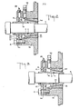
- Figure 2 is a cutaway view of the actually sealing means of this invention at the start of operation and
- Figure 3 is a cutaway view of the sealing means of this invention with the clearance reset.
- a pump 20 comprising a volute section 1 which is connected generally, by means of bolts or screws to a backplate shown as 2.
- An impeller 3 is located on a shaft 4 and extends into the cavity formed by the volute and backplate.
- the impeller can be opened or closed with vanes 21 through which liquid or any pumpable material flows.
- the liquid enters the pump through the pump inlet 22 and leaves through the pump outlet 23 going through the vanes 21 of the impeller 3.
- a closed impeller is shown through which the liquid passes, any other type impeller can be used in any type centrifugal pump.
- the shaft 4 is rotatably attached to a motor 24 which drives said impeller.
- a seal housing 26 which seal housing forms the back of the pump and surrounds the shaft and sealing means.
- an adjustable sleeve 5 made of appropriate metalic or non metalic material and having a conical tapered surface 25.
- Adjacent the conical surface 25 is an oppositely tapered conical-shaped bushing 27, which restricts the leakage through a close clearance between surface 25 of sleeve 5, and surface 28 of bushing 27.
- Surfaces 25 and 28 are adjacent each other. Both tapered surfaces 28 and 25 of the bushing and sleeve are concentric around the shaft.
- the bushing 27 is not movable or rotatable and is attached to or made part of the seal housing.
- Sleeve 5 is adjustable by way of set screw 63 attached at one end of the sleeve.
- an o-ring 17 around the shaft and within the sleeve 5, to prevent leakage between shaft 4 and sleeve 5.
- a greaselip seal 14 which can be a regular or split seal (in Figure 1-3 a split seal is shown) which surrounds the sleeve 5.
- a grease fitting 89 whereby one can lubricate the greaselip seal.
- a seal cap 30 holds the greaselip seal 14 in place around the shaft 4.
- a tube connector 94 which leads from the cavity 29 formed by the sleeve 5, the bushing 27, and the sealhousing 26 to the inlet of the pump 22. This cavity 29 communicates through the tube connector 94 to the inlet region of the pump housing 22.
- a cap screw 8 holds the grease seal assembly against the shaft 4 and is attached to the seal housing 26 thus forming also the above described cavity 29.
- the seal works as follows:
- the shaft 4 driven by the motor 24 rotates the impeller 3 and liquid or material to be pumped enters the inlet 22 and is pumped out the outlet 23 by the impeller 3.
- the shaft is rotatably mounted within the seal housing and when rotating the sealing means comes into play.
- When wear occurs one can adjust this seal by unscrewing set screw 63 and movinq the tapered sleeve 5 forward toward the impeller 3.
- the sleeve 5 can be moved forward only a distance to where the set screw is readily accessible.
- the greaselip seal 14 can also be easily removed should the sleeve have to be moved forward a distance where normally the set screw would then be covered by the grease seal.
- a special feature of this invention is that should leakage occur between the sealing means of the bushing 27 and sleeve 5, such that liquid enters cavity 29 the liquid will flow through the tube connector 94 back to the pump housing or inlet 22.
- the tube connector 94 allows any leakage of pressure or material to be circulated around to the pump inlet 22.
- the taper on the sleeve can be threaded with threads 60 particularly with the threads being on the sleeve taper surface 25 to further increase pressure drop and reduce leakage which is recirculated back to the pump suction.
- the number of threads per inch of the tapered sleeve surface 25 and the thread pitch are not critical to my invention and any standard pitch and number of threads can be used.
- the thread direction however must be such that when the sleeve rotates any liquid which leaks therethrouqh must be forced back towards the impeller and the interior of said pump.
- the greaselip seals 14 used in this invention can be any type greaslip seal known in the art. Particularly, it can be one with a split seal whereby the inner seal 61 is used to prevent leakage to the atmosphere and the outer seal 62 is used to prevent air from entering the pump while priming. As stated previously, the two seals of the grease seal 14 are grease lubricated through the grease fitting 89.
Landscapes
- Engineering & Computer Science (AREA)
- General Engineering & Computer Science (AREA)
- Mechanical Engineering (AREA)
- Structures Of Non-Positive Displacement Pumps (AREA)
- Glass Compositions (AREA)
- Sealing Using Fluids, Sealing Without Contact, And Removal Of Oil (AREA)
- Sealing Devices (AREA)
- Sealing Of Bearings (AREA)
- Sealing With Elastic Sealing Lips (AREA)
- Mechanical Sealing (AREA)
Priority Applications (1)
| Application Number | Priority Date | Filing Date | Title |
|---|---|---|---|
| AT83400228T ATE23387T1 (de) | 1982-02-08 | 1983-02-03 | Dichtung fuer pumpen. |
Applications Claiming Priority (2)
| Application Number | Priority Date | Filing Date | Title |
|---|---|---|---|
| US06/346,697 US4386786A (en) | 1982-02-08 | 1982-02-08 | Adjustable pump seal with tapered conical members |
| US346697 | 1982-02-08 |
Publications (3)
| Publication Number | Publication Date |
|---|---|
| EP0086151A2 true EP0086151A2 (de) | 1983-08-17 |
| EP0086151A3 EP0086151A3 (en) | 1983-11-16 |
| EP0086151B1 EP0086151B1 (de) | 1986-11-05 |
Family
ID=23360639
Family Applications (1)
| Application Number | Title | Priority Date | Filing Date |
|---|---|---|---|
| EP83400228A Expired EP0086151B1 (de) | 1982-02-08 | 1983-02-03 | Dichtung für Pumpen |
Country Status (9)
| Country | Link |
|---|---|
| US (1) | US4386786A (de) |
| EP (1) | EP0086151B1 (de) |
| JP (1) | JPS58146768A (de) |
| AT (1) | ATE23387T1 (de) |
| AU (1) | AU550810B2 (de) |
| BR (1) | BR8300527A (de) |
| CA (1) | CA1185483A (de) |
| DE (1) | DE3367435D1 (de) |
| ZA (1) | ZA83814B (de) |
Cited By (2)
| Publication number | Priority date | Publication date | Assignee | Title |
|---|---|---|---|---|
| FR2634831A1 (fr) * | 1988-07-29 | 1990-02-02 | Messer Griesheim Gmbh | Pompe centrifuge a transfert de fluide tres pur, notamment cryogene |
| CN103557177A (zh) * | 2013-11-12 | 2014-02-05 | 成都科盛石油科技有限公司 | 一种低比速离心泵 |
Families Citing this family (13)
| Publication number | Priority date | Publication date | Assignee | Title |
|---|---|---|---|---|
| US4780972A (en) * | 1988-03-21 | 1988-11-01 | Keene Wayne G | Wheelmotor drive for rotary cutterhead |
| JPH04300471A (ja) * | 1991-03-27 | 1992-10-23 | Shimadzu Corp | 流体機械 |
| US5165699A (en) * | 1991-07-25 | 1992-11-24 | Arco Chemical Technology, L.P. | Liquid full pressurized vessel seal |
| US5690341A (en) * | 1996-06-17 | 1997-11-25 | Ahlstrom Machinery Inc. | Method and apparatus for the facilitating the servicing of drive-shaft assemblies for pressurized vessels |
| US20070172367A1 (en) * | 2006-01-26 | 2007-07-26 | Janocko David J | Flow restricting devices in pumps |
| FR2920207B1 (fr) * | 2007-08-23 | 2009-10-09 | Alcatel Lucent Sas | Pompe a vide de type seche comportant un dispositif d'etancheite aux fluides lubrifiants et elements centrifugeur equipant un tel dispositif |
| US10054226B1 (en) * | 2015-11-25 | 2018-08-21 | Billy Dean Watson | Mechanical sealing system |
| CN108194372B (zh) * | 2018-02-10 | 2024-03-22 | 山东心传矿山机电设备有限公司 | 一种水陆两用立式排沙泵 |
| CN114450490B (zh) * | 2019-10-21 | 2024-09-20 | 苏尔寿管理有限公司 | 用于泵送阻隔液体的泵布置结构以及机械轴密封件 |
| CN111622980B (zh) * | 2020-04-23 | 2022-06-07 | 宁波巨神制泵实业有限公司 | 一种机械密封防异物磨蚀结构 |
| US12085087B1 (en) * | 2020-08-27 | 2024-09-10 | Timothy Neal Hilliard | Waterless gland assembly for rotating equipment |
| JP2023162560A (ja) * | 2022-04-27 | 2023-11-09 | 田中水力株式会社 | ラビリンスシール及びこれを用いたラビリンス隙間の調整方法 |
| CN116696763A (zh) * | 2023-06-16 | 2023-09-05 | 中车株洲车辆有限公司 | 一种螺杆泵 |
Family Cites Families (14)
| Publication number | Priority date | Publication date | Assignee | Title |
|---|---|---|---|---|
| US333049A (en) * | 1885-12-22 | Isaac w | ||
| US781648A (en) * | 1903-04-01 | 1905-02-07 | Eisenhuth Horseless Vehicle Company | Casing for compound motors. |
| US897189A (en) * | 1906-11-12 | 1908-08-25 | Giuseppe Belluzzo | Stuffing-box for elastic-fluid turbines. |
| US991225A (en) * | 1910-06-20 | 1911-05-02 | Albert B Morton | Stuffing-box for gas-meters. |
| US2574773A (en) * | 1945-08-21 | 1951-11-13 | Nat Tube Co | Roll mounting |
| US3114322A (en) * | 1959-04-09 | 1963-12-17 | Carrier Corp | Hermetic pump |
| US3195466A (en) * | 1959-05-25 | 1965-07-20 | Porter Co Inc H K | Electric motor construction |
| US3471157A (en) * | 1966-10-07 | 1969-10-07 | Judson S Swearingen | Shaft seal |
| NL6713596A (de) * | 1967-10-06 | 1969-04-09 | ||
| DE2063369C3 (de) * | 1970-12-23 | 1975-04-24 | Daimler-Benz Ag, 7000 Stuttgart | Lagerung einer Heizklappe im Auspuffleitungssystem einer Brennkraftmaschine |
| DE2254265C3 (de) * | 1972-11-06 | 1980-06-12 | Franz 4630 Bochum Klaus | Stopfbuchslose Chemiekreiselpumpe |
| DE2720135C3 (de) * | 1977-05-05 | 1980-09-25 | Georg Mueller Kugellagerfabrik Kg, 8500 Nuernberg | Spalt- bzw. Labyrinthdichtung |
| JPS5460109U (de) * | 1977-10-06 | 1979-04-25 | ||
| US4304411A (en) * | 1980-04-17 | 1981-12-08 | Mechanical Technology Incorporated | Magnetic/centrifugal-fluid seal |
-
1982
- 1982-02-08 US US06/346,697 patent/US4386786A/en not_active Expired - Lifetime
-
1983
- 1983-02-02 AU AU10933/83A patent/AU550810B2/en not_active Expired
- 1983-02-03 EP EP83400228A patent/EP0086151B1/de not_active Expired
- 1983-02-03 AT AT83400228T patent/ATE23387T1/de not_active IP Right Cessation
- 1983-02-03 DE DE8383400228T patent/DE3367435D1/de not_active Expired
- 1983-02-03 CA CA000420873A patent/CA1185483A/en not_active Expired
- 1983-02-03 BR BR8300527A patent/BR8300527A/pt not_active IP Right Cessation
- 1983-02-07 ZA ZA83814A patent/ZA83814B/xx unknown
- 1983-02-08 JP JP58018278A patent/JPS58146768A/ja active Granted
Cited By (2)
| Publication number | Priority date | Publication date | Assignee | Title |
|---|---|---|---|---|
| FR2634831A1 (fr) * | 1988-07-29 | 1990-02-02 | Messer Griesheim Gmbh | Pompe centrifuge a transfert de fluide tres pur, notamment cryogene |
| CN103557177A (zh) * | 2013-11-12 | 2014-02-05 | 成都科盛石油科技有限公司 | 一种低比速离心泵 |
Also Published As
| Publication number | Publication date |
|---|---|
| US4386786A (en) | 1983-06-07 |
| EP0086151B1 (de) | 1986-11-05 |
| AU550810B2 (en) | 1986-04-10 |
| BR8300527A (pt) | 1983-11-08 |
| ZA83814B (en) | 1983-10-26 |
| CA1185483A (en) | 1985-04-16 |
| EP0086151A3 (en) | 1983-11-16 |
| JPS58146768A (ja) | 1983-09-01 |
| DE3367435D1 (en) | 1986-12-11 |
| AU1093383A (en) | 1983-08-18 |
| JPS6350591B2 (de) | 1988-10-11 |
| ATE23387T1 (de) | 1986-11-15 |
Similar Documents
| Publication | Publication Date | Title |
|---|---|---|
| US4386786A (en) | Adjustable pump seal with tapered conical members | |
| US5553868A (en) | Seal cavity throat bushing | |
| US5921748A (en) | Centrifugal pump | |
| US9353763B2 (en) | Centrifugal pump, a shaft sleeve and a stationary seal member | |
| CA2150293C (en) | Centrifugal pump | |
| US3088416A (en) | Centrifugal pump | |
| US20130062832A1 (en) | Flow machine, slide ring seal thereof, body part for said slide ring seal and method of fastening said slide ring seal to said flow machine | |
| US3272137A (en) | Self-priming pump | |
| GB2254664A (en) | Barrier system for the lubricating oil for the bearings of a centrifugal compressor with labyrinth seals installed in a confined environment | |
| US5125672A (en) | Shaft sealing arrangements | |
| US4269564A (en) | Flow control device | |
| US1967316A (en) | Pump | |
| US6287074B1 (en) | Mechanical seal for shafts and axles | |
| US5152663A (en) | Centrifugal pump | |
| US4460180A (en) | Sealing of a shaft in a centrifugal pump and a method for effecting the sealing | |
| US2667128A (en) | Submersible pump | |
| US20090045589A1 (en) | Bushing and Lantern Ring for Rotary Fluid Pumping Equipment | |
| US2265448A (en) | Fluid actuating device | |
| US3635581A (en) | High-pressure centrifugal pump | |
| US6533540B1 (en) | Double-seal/oil-reservoir system for a motor/pump assembly | |
| US4342537A (en) | Impeller pump and seal | |
| CN1055747C (zh) | 无粉尘离心泵装置 | |
| GB2150221A (en) | Multistage centrifugal pumps | |
| RU2105201C1 (ru) | Центробежный насос | |
| KR960010213Y1 (ko) | 고압펌프의 패킹상자 압력 유지장치 |
Legal Events
| Date | Code | Title | Description |
|---|---|---|---|
| PUAI | Public reference made under article 153(3) epc to a published international application that has entered the european phase |
Free format text: ORIGINAL CODE: 0009012 |
|
| AK | Designated contracting states |
Designated state(s): AT BE CH DE FR GB IT LI LU NL SE |
|
| ITCL | It: translation for ep claims filed |
Representative=s name: SOCIETA' ITALIANA BREVETTI S.P.A. |
|
| PUAL | Search report despatched |
Free format text: ORIGINAL CODE: 0009013 |
|
| AK | Designated contracting states |
Designated state(s): AT BE CH DE FR GB IT LI LU NL SE |
|
| 17P | Request for examination filed |
Effective date: 19840507 |
|
| GRAA | (expected) grant |
Free format text: ORIGINAL CODE: 0009210 |
|
| ITF | It: translation for a ep patent filed | ||
| AK | Designated contracting states |
Kind code of ref document: B1 Designated state(s): AT BE CH DE FR GB IT LI LU NL SE |
|
| REF | Corresponds to: |
Ref document number: 23387 Country of ref document: AT Date of ref document: 19861115 Kind code of ref document: T |
|
| REF | Corresponds to: |
Ref document number: 3367435 Country of ref document: DE Date of ref document: 19861211 |
|
| BECA | Be: change of holder's address |
Free format text: 861105 *PACO PUMPS INC.845-92ND AVENUE, OAKLAND CALIFORNIA 94604-2924 |
|
| BECH | Be: change of holder |
Free format text: 861105 *PACO PUMPS INC. |
|
| ET | Fr: translation filed | ||
| PG25 | Lapsed in a contracting state [announced via postgrant information from national office to epo] |
Ref country code: LU Free format text: LAPSE BECAUSE OF NON-PAYMENT OF DUE FEES Effective date: 19870228 |
|
| PLBE | No opposition filed within time limit |
Free format text: ORIGINAL CODE: 0009261 |
|
| STAA | Information on the status of an ep patent application or granted ep patent |
Free format text: STATUS: NO OPPOSITION FILED WITHIN TIME LIMIT |
|
| 26N | No opposition filed | ||
| REG | Reference to a national code |
Ref country code: CH Ref legal event code: PUE Owner name: PACO PUMPS, INC. |
|
| REG | Reference to a national code |
Ref country code: FR Ref legal event code: TP |
|
| NLS | Nl: assignments of ep-patents |
Owner name: PACO PUMPS, INC. TE OAKLAND, CALIFORNIE, VER. ST. |
|
| ITPR | It: changes in ownership of a european patent |
Owner name: CESSIONE;PACO PUMPS INC. |
|
| REG | Reference to a national code |
Ref country code: GB Ref legal event code: 732 |
|
| PGFP | Annual fee paid to national office [announced via postgrant information from national office to epo] |
Ref country code: LU Payment date: 19891229 Year of fee payment: 8 |
|
| ITTA | It: last paid annual fee | ||
| EAL | Se: european patent in force in sweden |
Ref document number: 83400228.9 |
|
| PGFP | Annual fee paid to national office [announced via postgrant information from national office to epo] |
Ref country code: SE Payment date: 20011227 Year of fee payment: 20 Ref country code: CH Payment date: 20011227 Year of fee payment: 20 |
|
| REG | Reference to a national code |
Ref country code: GB Ref legal event code: IF02 |
|
| PGFP | Annual fee paid to national office [announced via postgrant information from national office to epo] |
Ref country code: BE Payment date: 20020114 Year of fee payment: 20 |
|
| PGFP | Annual fee paid to national office [announced via postgrant information from national office to epo] |
Ref country code: AT Payment date: 20020115 Year of fee payment: 20 |
|
| PGFP | Annual fee paid to national office [announced via postgrant information from national office to epo] |
Ref country code: GB Payment date: 20020129 Year of fee payment: 20 |
|
| PGFP | Annual fee paid to national office [announced via postgrant information from national office to epo] |
Ref country code: NL Payment date: 20020207 Year of fee payment: 20 |
|
| PGFP | Annual fee paid to national office [announced via postgrant information from national office to epo] |
Ref country code: FR Payment date: 20020221 Year of fee payment: 20 |
|
| PGFP | Annual fee paid to national office [announced via postgrant information from national office to epo] |
Ref country code: DE Payment date: 20020328 Year of fee payment: 20 |
|
| PG25 | Lapsed in a contracting state [announced via postgrant information from national office to epo] |
Ref country code: LI Free format text: LAPSE BECAUSE OF EXPIRATION OF PROTECTION Effective date: 20030202 Ref country code: GB Free format text: LAPSE BECAUSE OF EXPIRATION OF PROTECTION Effective date: 20030202 Ref country code: CH Free format text: LAPSE BECAUSE OF EXPIRATION OF PROTECTION Effective date: 20030202 |
|
| PG25 | Lapsed in a contracting state [announced via postgrant information from national office to epo] |
Ref country code: NL Free format text: LAPSE BECAUSE OF EXPIRATION OF PROTECTION Effective date: 20030203 Ref country code: AT Free format text: LAPSE BECAUSE OF EXPIRATION OF PROTECTION Effective date: 20030203 |
|
| REG | Reference to a national code |
Ref country code: GB Ref legal event code: PE20 Effective date: 20030202 |
|
| BE20 | Be: patent expired |
Owner name: *PACO PUMPS INC. Effective date: 20030203 |
|
| REG | Reference to a national code |
Ref country code: CH Ref legal event code: PL |
|
| EUG | Se: european patent has lapsed | ||
| NLV7 | Nl: ceased due to reaching the maximum lifetime of a patent |
Effective date: 20030203 |