EP0086184A2 - Dispositif d'amortissement sonore - Google Patents
Dispositif d'amortissement sonore Download PDFInfo
- Publication number
- EP0086184A2 EP0086184A2 EP83850021A EP83850021A EP0086184A2 EP 0086184 A2 EP0086184 A2 EP 0086184A2 EP 83850021 A EP83850021 A EP 83850021A EP 83850021 A EP83850021 A EP 83850021A EP 0086184 A2 EP0086184 A2 EP 0086184A2
- Authority
- EP
- European Patent Office
- Prior art keywords
- sound
- acoustic
- absorption
- chamber
- frequency
- Prior art date
- Legal status (The legal status is an assumption and is not a legal conclusion. Google has not performed a legal analysis and makes no representation as to the accuracy of the status listed.)
- Withdrawn
Links
Images
Classifications
-
- G—PHYSICS
- G10—MUSICAL INSTRUMENTS; ACOUSTICS
- G10K—SOUND-PRODUCING DEVICES; METHODS OR DEVICES FOR PROTECTING AGAINST, OR FOR DAMPING, NOISE OR OTHER ACOUSTIC WAVES IN GENERAL; ACOUSTICS NOT OTHERWISE PROVIDED FOR
- G10K11/00—Methods or devices for transmitting, conducting or directing sound in general; Methods or devices for protecting against, or for damping, noise or other acoustic waves in general
- G10K11/16—Methods or devices for protecting against, or for damping, noise or other acoustic waves in general
- G10K11/172—Methods or devices for protecting against, or for damping, noise or other acoustic waves in general using resonance effects
Definitions
- the present invention relates to a sound-damping, acoustic device of the kind comprising a sheet-material member which can be set, by sound, into oscillatory motion transversely to its geometrical extension, and which forms at least a part of the defining walls of a chamber.
- Sound is created by the wave-form motion of a medium, this wave motion propagating at a velocity which is dependent upon the nature of the medium through which the sound travels.
- This medium may be a gas, a liquid, or a solid.
- speed of sound is about 344 ms-1. The speed is greater, however, when propagating through a solid body with small internal damping,and decreases when damping is high.
- Sound energy occurs as a disturbance in the medium, and causes the particles in the. medium to oscillate about a position of equilibirium. When the particles oscillate in the same direction as that in which the sound wave propagates, acoustic energy manifests as a longitudinal wave.
- the acoustic energy flows in the medium in the same direction as the wave.
- complex wave forms may also occur, i.e. the acoustic energy can change direction and flow perpendicularly to the direction in which the wave propagates.
- the wavelength is determined by the smallest distance between mutually adjacent particles in the medium which have the same direction of motion and phase.
- Wave frequency is derived from the relationship between the speed of propagation in the medium, the oscillation interval, and the number of oscillations per unit of time.
- the sound is affected by obstacles located in its path of propagation. The extent to which the sound is affected is determined by the specific frequency of the sound.
- the extent to which the sound is affected is substantially negligible. If the frequency is high (short waves) and the size of the obstructing surface is comparable with the wavelength, then propagation of the wave practically ceases and the sound must change direction. If the obstructing surface is totally reflective at this frequency, the sound is reversed towards the acoustic source. If the sound is able to penetrate into the obstructing surface, the obstruction will take-up a certain amount of the incoming acoustic energy, which is therewith absorbed and transmitted, while the remainder of the acoustic energy is reflected back to the sound- -.. source. If there is no obstruction in the propagating path of the sound- wave, then so-called free sound propagation is obtained.
- That part of the sound from the sound-source which has not been absorbed by a screen, in accordance with the above, will travel through the air until it reaches a solid room-defining wall. If this wall is totally reflective, the sound will be returned back towards the sound-source and towards the room-defining wall opposing the first mentioned wall, and also towards other room-defining walls, in relation to the angle of incidence of the soundwave - Provided that the surface of the room-defining wall remains fixed when subjected to the kinetic energy of the soundwave, the speed at which the particles move in the soundwave approaches zero at a given distance from said surface, and becomes zero at said surface. If the particle movement in the wave is sinusoidal, the particle speed is at a maximum at a distance from the defining surface equal to one quarter of the wavelength.
- the surface is not fixed, i.e. the surface vibrates as a function of the energy of the incoming soundwave, the surface of said defining wall will act as an alternatively codirectional and counter- directional sound-source, and hence the location of the zero-point becomes physically indefinite and frequency related.
- the room-defining wall is not acoustically undampened, certain incident acoustic energy will be absorbed, transmitted and reflected.
- the absorption properties of the wall can be greatly increased by covering the surface of said wall with a suitable sound-absorbing acoustic device. This will prevent the sound from returning back to the sound-source and towards other room-defining surfaces.
- 100 % absorption is achieved, i.e. if the physical area of the surface is 1 m 2 then the absorption is also 1 m 2 .
- a measurement of the mean absorption for a room having a given surface area can be defined as the relationship between the total room-absorption and said surface area.
- the whole of the room surface must be covered with an absorbing material, which permits the entire sound energy to be absorbed at the surface - 100 % absorption at the surface.
- the sound is halved with each doubling of the distance from the sound-source. If the sound-source is cut-off abruptly, then the sound will cease immediately, i.e. the reverberation time for the room reaches zero, since no reflected sound-pressure can be built up therein.
- the fundamental room acoustics is determined by a number of factors.
- the geometrical shape of the room and the relationship between the nature of the different room-defining surfaces with respect to shape, mechanical stability and intrinsic absorption are of great importance as to how a generated sound spectrum behaves in the room.
- the relationship,between sound arriving directly from the sound-source and sound arriving from the surfaces of the room is dependent on where the location,from which the sound is observed,is positioned in the room and in relation to the sound-source. If this observing location is located in the immediate vicinity of the sound-source in the direct field - the acoustics of the room can have had no influence, or only a negligible influence. Consequently, any reduction of noise from the sound-source will be only slight or none at all.
- the reflected sound field becomes dominant over the direct field, and hence sound reduction derived from absorption material placed adjacent or on a defining wall is at a maximum adjacent said wall. It will be understood from this that it is impossible to reduce noise at the sound-source to any appreciable extent, by acoustically dampening the walls and ceiling of a room.
- the advantage of absorption at a wall surface is that the distance law becomes effective sooner. Therewith, absorption of sound at a distance from the sound-source results in the level of sound being halved progressively earlier (i.e. at a shorter distance from the sound-source) the higher the absorption at the wall.
- an acoustic oscillating circuit has inertia, a certain amount of time will lapse before the change in pressure level is effected, which takes place in the form of an acoustic build-up, which proceeds in accordance with the frequency response of the room, the natural resonance frequencies of the room manifesting in the step function which is developed when the pressure change applied has reached equilibrium and when a repeated change in pressure takes place - e.g. when an applied pressure rise has been maintained for a given length of time and then cut off.
- Helmholz absorbents of various designs which are intended for special functions in certain frequency ranges.
- brief mention will be made below of the principal function of known oscillatory member, also intended for use in discrete frequency ranges.
- a Helmholz resonator comprises an air volume enclosed in a chamber provided with an opening to the surroundings. The opening tunes the interior of the chamber to resonate at a given frequency.
- This type of absorbent is used to absorb discrete frequencies, such as the main resonance frequency of the room in question for example, and has at the Helmholz-resonance, in principle, 100 % efficiency. Since the frequency in question may, for example, be 25 Hz, which '-.becomes the dominating resonance frequency in a room and which is the frequency which one wishes to absorb, the absorbent may become very large in volume. Naturally, a large quantity of air has a relatively large mass, and hence a significant impulse inertia will occur in the resonator.
- Absorption at medium-low frequencies may be improved by using a Helmholz resonator absorbent of smaller physical dimensions.
- This absorbent has the form of a cavity construction, having a perforated cover-plate mounted on studs.
- the device is mounted on a defining wall, and has a high acoustic efficiency within a given, limited frequency range. Since these devices are often designed for frequencies where the volume does not become excessive, the acoustic properties with transient exitation of the resonator construction may, in theory, be considered good.
- the cover panels are often too pliable, and hence they will oscillate in sympathy at frequencies which are lower than the intended frequency range.
- Helmholz resonator comprises oscillatory panels mounted on studs.
- a thin and flexible panel made from imperforate plywood can be combined with the rearwardly located air chamber, so as to bring the panel into maximum oscillation at the resonance frequency of this acoustic system.
- Good absorption at this resonance frequency and negligible absorption at other frequencies is characteristic of such an oscillating panel.
- the construction principle incorporating a homogenous, oscillating membrane which oscillates on an air spring it is possible to obtain a low resonance frequency with a considerably smaller volume parameter than that which must be used for cavity resonator constructions.
- the resistive dampening of the oscillatory motion is small and approaches zero when the panel oscillats at resonance frequency.
- this construction for improved low-frequency absorption suffers the disadvantage that the poor damping provided results in significant instability for transient exitation, and significant intrinsic noise must be expected. It is possible to dampen the-construction internally with fibrous material, although the efficiency of the construction will then rapidly decrease as dampening increases. Acceptable transient stability can only be achieved when the panel is dampened purely mechanically by a rearwardly arranged fibrous material, which by contact action prevents the panel from oscillating. Obviously, the panel then has ceased to function in the manner intended.
- Fibrous absorbents most frequently have a thickness of 50 - 100 mm and a density which lies between 40 - 70 kgm -3 . Such absorbents therefore become self-supporting, when made, for example, in sizes of 1200 x 600 mm.
- a typical feature of the fibrous mineral-wool absorbent is that the velocity of sound propagation in the material is roughly halved, i.e. to about 172 ms-1. Absorption can maximally reach 100 %, provided that the material is not so dense that sound is reflected away from the surface at a certain frequency.
- the absorbents function by short-circuiting the acoustic energy received. Absorption can only take place when the particles carried in the sound wave are transported through the fibre-material, and when the particle velocity is high in that part of the transportion path which is contained within the fibre-structure .
- each individual absorbent is caused to oscillate about its natural resonance frequency, which can be very low, for example as low as 5 - 40 Hz, and hence a significant and highly disturbing low-frequency situation with generated random noise may occur also in acoustically light environments.
- the object of the present invention is to provide a novel and improved acoustic device for damping sound, with which the disadvantages encountered with conventional sound absorbents in accordance with the aforegoing are at least substantially overcome.
- an acoustic device of the kind mentioned in the introduction which is also characterized by the combination that the member is substantially free-swinging; that the chamber is at least substantially acoustically closed;and that the device is provided with means for damping displacement of said member transversely to said geometrical extension in proportion to changes in the rate of displacement.
- the acoustic device obtains a high efficiency and becomes well impedance-matched to sound-energy received, in a broadened frequency range, especially extended towards low frequencies.
- the device also exhibits an improved dynamic function upon transient exitation of the same, since sound radiation deriving from natural oscillations of the surfaces of the device is markedly reduced, thereby optimizing its transient response.
- the sheet-material member may comprise an air permeable or air-tight plate, which may be planar or curved, and may be rigid, said plate then being resiliently mounted at its edges, so as to be able to oscillate in the aforedescribed manner in co-action with the air-filled volume of the chamber located rearwardly of said manner.
- the member comprises however, a relatively thin, substantially planar, porous, fibrous or perforated plate, which is substantially fixed against oscillatory motion along its edge-defining regions and which when oscillating coacts with an air spring formed by a rearwardly located air-filled chamber space, the volume of the air-filled space forming said air spring being so selected in relation to the density of said member, its mass and its flow resistance, that the oscillatory motion of said member forms a maximum at the resonance frequency of the device, said maximum appearing in the region of the centre of said member and being dampened by the flow resistance.
- the impedive sound absorption i.e. through surface impedance obtained sound absorption
- said member may have located substantially symmetrically about its geometric centre at least one area in which it is more permeable to air than the remainder of said member.
- said area may be enclosed by a tubular part arranged in the direction of oscillations of the member, for example so that said area is sharply defined and also so that said area obtains a volume parameter whose magnitude can be determined readily and precisely by varying the length of said tube, thereby to achieve a degree of freedom with respect to the resistive components of said area.
- the tube with inherent or supplied resistance can constitute the sole oscillation-controlling means of the device, which means when inserted in the centre point of the member constitutes a particularly effective dynamic valve at the most sensitive point of the oscillating circuit for ventilation of the chamber to the surroundings.
- the device may alternatively, or in addition, exhibit at least one opening which establishes a connection between the volume enclosed by the chamber and the volume enclosing said de- .vice, and which has arranged therein a flow resistance of such magnitude as to considerably dampen the amplitude of oscillatory motion of said member at the resonance frequency of the device.
- the device may include at least one acoustic opening which establishes a connection between the volume enclosed by the chamber and the volume enclosing the device, which opening substantially acoustically loads said member so as to substantially inductively increase the acoustic efficiency of the device around the resonance frequency of the circuit formed by the opening and the enclosed volume.
- this opening may also exhibit resistance for resistively reducing the acoustic coupling between said opening and said member.
- the device may advantageously have arranged between said member and the opposite chamber-defining wall at least one acoustically resistive member, which may also exhibit significant flow resistance.
- the chamber-defining wall located opposite said member may comprise a rigid plate, or a wall on which the device is mounted.
- the chamber-defining wall located opposite said member comprises a member which is substantially identical to the first- mentioned member, whereby the efficiency of the device per unit of mounting surface area can be more than doubled as a result of the coaction of the mutually opposing members, which are interconnected by the volume of air enclosed therebetween, in the oscillating circuit formed by said members and said volume of air.
- This synergistic effect is particularly emphasized in the frequency range in which the inherent acoustic absorption of the members used is high.
- the device according to the invention has a certain characteristic sensitivity to the angle of incidence of sound and to the distance to the sound-source.
- This sensitivity can be amplified at the side of the device where an oscillatory member is arranged, when the chamber-defining side opposite said member -has arranged therein a port or opening which is of considerable size in relation to the area of said member and which incorporates an acoustic resistance for generating at the mouth of said port a sound pressure which is directed against the sound pressure arriving from the surroundings.
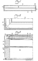
- FIG. 1 illustrates the principle design of a device 10 according to the invention.
- the device includes a chassis comprising walls 11, 12, 13, which can be made in two oarts and which are joined together by means of mechanical sealing means so as to be airtight.
- the chassis is suitably constructed from plastic or aluminium sections having a thickness of 1 - 3 mm and manufactured so as to provide a structure which is mechanically rigid.
- the sides of the chassis are able to absorb some acoustic energy, it is the members 14 and 15 which constitute the actual absorption area of the device 10. These members may be given different forms according to the purposes for which the device is to be used, and in accordance with the principle of the invention.
- the member 14 may have the form of an oscillatory element which can be caused to oscillate by sound in a direction transversely to the geometrical extension of said member, while the member 15 may be given a considerably greater rigidity and density, in which case the member 14 becomes the predominant absorption surface and is directed towards the acoustic source, while the member 15 forms a rear wall for the oscillatory member 14 and is substantially passive from an ocillatory aspect.
- a construction of this design may be called a single absorbent and obtains an absorption characteristic which permits an angular absorption which becomes substantially hemi-spherical and substantially only active in respect of sound incident on the member 14.
- This version of the invention may be used to advantage when the device is to be mounted directly on a defining wall, or in the case of applications where the absorption effect is desired to be directed towards a certain sound-source, while simultaneously acoustic screening of the sound-source towards the surroundings is aimed at.
- a typical example of such an application is the building-in and acoustic separation of discrete sound- sources, for example a noisy machine.
- the device can then be manufactured with an oscillatory member 14 and a stationary member 15, with the member 14 being provided on at least the surface facing the surroundings with a mechanically stabilizing staple fibre layer applied on a glass-fibre core having a thickness of, for example, 20 - 40 mm and a density of about 20 kgm- 3 , and with the member 15 being made substantially heavier and more rigid than member 14, and having a thickness of, for example 20 mm and a density of about 100 kgm .
- the resonance frequency of the device 10 can be altered by providing internal damping, by inserting fibre absorbents on the inside of the member 15 and/or along the sides 11, 12, 13, of the chassis.
- the oscillatory member 14 When the device is in function, the oscillatory member 14 is displaced by an acoustic pressure change, which causes a change in the pressure in the chamber 16 enclosed by the chassis and members 14, 15. This change in pressure either causes the internal air to be compressed or decompressed, depending upon the direction of motion of the member 14. Thus, the condition at which the mechanical circuit is in balance is disturbed, and hence the differential part of the internal- pressure change is able to pass, to a certain quantity, through the members 14, 15. When this takes place, the oscillatory motion is dampened through the additional flow-resistance friction component, which is determined at all times by the dynamic impact of the pressure change.
- The- pressure change at the receiving surface of member 14 would approach zero and the incoming soundwave would be reflected in the same manner as it would with a normal, fixed defining surface. Because the flow resistance permits limited equalization of pressure to take place over a given period of time, and because the fixed member 15 having the higher resistance to flow passively absorbs the residual pressure change in chamber 16, this residual pressure change being applied through displacement of the member 14, it is possible, however, to achieve that a given and resistively dampened positional change occurs at the surface of member 14, whereupon the amplitude of the incoming pressure wave is taken up by the member 14 and is transmitted to the air in the chamber, said air transmitting the energy to the substantially fixed absorption member 15 of high density and great weight, this latter member converting residual energy to heat.
- the pick-up and conversion of the applied acoustic energy is executed as a function of the acoustic impedance prevailing in the oscillating circuit for each frequency and impulse time, and hence the acoustic system formed is automatically matched within the entire oscillating range and also includes a variably effective resistive damping.
- a fast reacting absorption system exhibiting high impulse damping and high acoustic efficiency in a functional range mainly enlarged towards low frequencies.
- this system constitutes a matched acoustic absorption impedance to the incoming sound, and will only generate minor quantities of disturbing acoustic energy, since it is well dampened in its oscillatory function.
- Constructions having an oscillating area of 0,5 m 2 and an enclosed volume of 100 dm 3 can be given a resonance frequency of about 30 - 50 Hz and may have at this frequency an effective absorption approaching 100 %.
- a device of the described design may, for example, have external measurements of about 1150 x 550 x 200 mm, and hence a significant insertion effect can be obtained for a prescribed mounting surface, something which cannot be achieved with known techniques.
- the resultant acoustic absorption -achieved by the device 10 is higher than that achieved with the oscillatory member itself, and can become approximately twice as high in the absorption range lying immediately above the resonance frequency and up to the upper limit frequency determined by the surface-character of member 14, normally above 4000 Hz.
- Tis is due to the fact that the device 10 behaves as a substantially matched acoustic impedance in the whole of the frequency range for said device, and hence also the energy component in the sound-wave comprising non-real (reactive) energy is absorbed by the device 10, instead of being reflected away from the surface of member 14, as is the case with a traditional fibre absorbent only capable of absorbing real acoustic energy.
- the member 15 of the device illustrated in Figure 1 may comprise a non-absorbing defining wall, such as an existing defining surface or wall on the site where the device is to be mounted.
- the member 15 should be provided with a suitable fibre absorbent which lies free from the member 14, so as to avoid discrete reflexes from the wall surface and to ensure sufficient internal damping in the chamber 16, so that low-frequency sound is also absorbed at the defining wall, in the aforedescribed manner.
- a plurality of oscillatory members 14 can be placed in the immediate vicinity of one another, across an absorption chamber which is common to several such members.
- the device can also be designed in a so-called differential mode, i.e. with two co-acting oscillatory members of substantially identical construction. Since the oscillatory members used will have substantially equal mechanical resonance frequencies and equal flow resistances, they will between themselves develop a differential effect. In doing so they will dampen each others' oscillations by addition and subtraction which is related to their mutually determined oscillatory velocity, amplitude and motional direction. There is obtained a particularly effective, dynamic damping in addition to an absorption characteristic which is substantially equivalent to both members. There is therefore obtained an additional increase in the total absorption obtainable when using the absorption members 14, 15 individually; this increase may be as much as two to four times that obtained with individual members 14, 15.
- the acoustic resonance frequency of the differential system is approximately halved in comparison with an equivalent single system according to the invention.
- the acoustic resonance frequency of the differential system is approximately halved in comparison with an equivalent single system according to the invention.
- previously unknown insertion effects on a prescribed mounting surface are obtained over a very wide frequency range.
- a particularly high value of room damping in dB/seconds for transient sound effects is obtained compared with that obtainable when using known techniques.
- the device according to Figure 1 can also be provided with one or two oscillatory members 14, 15 suspended at their defining edges in the chassis through an elastic attachment means.
- a substantially planar and optionally rigid, fibrous member having a thickness of about 20 mm may be fixedly positioned in a cellular rubber frame having a width of about 10 to 50 mm, said frame being attached to the chassis in an air-tight fashion.
- An alternative attachment variant which can be used, to advantage, when mounting a thin and substantially inflexible plastic or sheet-like member may comprise a thin neoprene rubber frame, which is suitably stretched in the plane of the member so as to obtain a certain amount of tension between the oscillatory member and the chassis when said frame is mounted in the extension of the member to the chassis.
- the fastening of said edge-suspension means and the extension of said means in said plane can then be tuned to determine the mechanical resonance frequency of a rigid member in the device 10.
- the rubber frame may be chosen to be about 10 - 50 mm in width and then be about 0.5 - 2 mm in thickness.
- the mechanical mass of the member 14 or 15 and the lateral tension under which they are fastened in said frame determines the resonance frequency at which the member will oscillate in piston- like fashion in the chassis of the device 10.
- an acoustic resonance frequency at which the oscillatory displacement of the surface of said member is at a maximum.
- the device 10 When none of the oscillatory members includes flow resistance which connects the internal volume to the surroundings, the device 10 is provided with one of the other prescribed means which provide a damping effect upon the oscillation of the members.
- the damping in the enclosed acoustic chamber 16 When desiring to regulate the damping in the enclosed acoustic chamber 16 to a given damping effect, or to change and to control the resultant absorption characteristic or acoustic variations of the absorption device in a series production of equivalent units, such as to displace the resonance frequency of the device, the sound reduction figure in a given frequency range etc., absorbing plate members can be inserted between the main sound-absorbing member 14 and the opposing surface of members 15. It may be necessary to apply this method in order to obtain a broad absorption range when using oscillatory members having a low-absorbing inherent damping.
- the absorption ability of the oscillatory member 14 in such a design will diminish towards high frequencies, and hence the inclusion of an absorbing partition wall in chamber 16 will result in the acoustic energy absorbed being transferred to the surface of the partition wall, to be absorbed therein.
- the partition wall may include penetrating openings or slots, which regulate the flow of air in the interior of the device 10.
- Figure 2 illustrates a suitable design of a chassis comprising aluminium or plastics sections, and shows a corner part of a device which functions in accordance with the principle described with reference to Figure 1.
- Figure 3 is a sectional-view of the corner part shown in Figure 2, with an inserted fibre member 14 which has bonded thereto outer layers 18 of, for example staple fibres or plastics film.
- Figure 3 illustrates a half of a differential construction having two opposed oscillatory members, or of a construction having one oscillatory absorption member and one substantially passive absorption member.
- the section located around edge 19 at the bottom of Figure 3 can readily be adapted for mounting the device on a wall, when the wall as such may carry a suitable passive absorbent, when such is used.
- the fibre absorbent 14, shown at the top of Figure 3 is fixedly attached to a fork-like absorbent holder 20 arranged in an aluminium or plastics section, and is suitably fixed against motion and sealed by means of continuous rubber glue string 21 applied at the edge of the absorbent 14 adjacent the fork-like surfaces of the section.
- This method of mounting is essential to avoid edge-oscillations of the absorbent 14; to obtain air-tight sealing; and to ensure that the absorption member 14 can be excited by sound energy and respond with an oscillation motion linearly and without unnecessary change of the edge tension in the plane of the absorption surface and without the generation of mechanical secondary sound from the section- absorbent-joint.
- the chassis may be undampened, since the oscillatory member 14 then constitutes an excellent means for damping resonance phenomena and the formation of standing waves in the chamber 16.
- Joining of the corner illustrated in Figure 2 should be effected so as to ensure an air-tight joint and also to ensure that mechanical displacements in an otherwise stable chassis are avoided.
- the centre beam 23 in the chassis section 24, Figure 3 is intended to mechanically stabilize the section against oscillation. It is essential that the device as a whole is made while taking into account that the chassis becomes acoustically conductive if it is allowed to vibrate unduly, in which case very powerful related noise may emanate from the absorbent at discrete frequencies.
- the device should be mounted against a suspension structure made, for example, of aluminium sections, so as to isolate the chassis of the device somewhat against vibration effects, by providing, for example, the supporting section or the mounting edge of the device located against said section with a thin layer of plastics or rubber material.
- the device should be mounted such that the sound-absorbing surface faces the sound-source and is perpendicular thereto.
- Devices of the differential type should be mounted in a corresponding manner, but with an air gap between the units " 10, such as to allow the sound to act on both members 14, 15. The air gap may then, for example, be 50 mm in width.
- the most evenly distributed sound absorption in the spectrum is generally obtained with a device of the differential type, when each alternate surface unit is left free, so that only 50 % of the mounting surface is used.
- the references 25 and 26 identify respectively binding and stiffening connecting elements bonded in grooves in the sections.
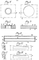
- valve means 27 Illustrated in Figures 4 and 5 is a dynamically active valve means 27 which is intended to be incorporated in an oscillatory member 14, or optionally in a substantially passive member in accordance with the invention.
- the resistive component, identified at 28 should be placed in the mouth of the tubular part 29, in a manner such that the resistance acts in the surface of the member 14 in a direction towards the sound-source.
- the valve means 27 should be mounted in the geometric centre point of the oscillator member 14, since the damping of the member achieved through the valve means is at a maximum effect and also acts symmetrically.
- Dimensioning of the valve means 27 is determined by whether any other connection to the surroundings of the acoustical circuit is used or not and by whether the oscillatory member or each oscillatory member is completely impermeable or incorporates a flow resistance determined by the density, thickness and area of said member.
- the tubular part 29 extends in the direction of oscillation of the member 14, and hence variations can be obtained in the viscous flow friction of the device, this friction increasing with the length of the tubular part 29.
- the valve means 27 can be provided with a fully open mouth area, for example an area of about 5 - 20 cm , and for example may have a volumetric parameter (50 - 200 cm 3 ) which is greater by roughly a power of 10, thereby achieving substantially viscous damping of the oscillatory member-14.
- a volumetric parameter 50 - 200 cm 3
- a purely resistive and damping- increasing friction-parameter component by stretching over said mouth area facing the surroundings a thin, fine-mesh net 30, for example a metal net having a size of 100 - 400 mesh, or for example a layer of staple-fibre having a density of 50 g m -2 , i.e. a thickness of about 0.3 mm.
- the net structure 30 is not allowed to vibrate.
- Glass fibre for example, can be mounted in the actual tube 29, whereby an additional friction damping is provided.
- the flow resistance must not be so great as to cause the valve means 27 to be ineffective.
- Figures 6 and 7 illustrate a dynamically active valve means suitable for use when a porous, or fibrous, passive member or oscillatory member 14 is used.
- the member for example, may have a density as low as 20 kgm - 3 and may have a thickness of 20 mm, and hence it may be desirable to change its total flow resistance calculated across the oscillatory surface. This can be done by covering one surface of said member, preferably that surface which borders onto the chamber 16, with an air-impermeable and thin, resilient material, for example a plastics film 32, or alternatively both surfaces of said member may be covered with said material.
- the central area 31 of the member 14 By allowing the central area 31 of the member 14 to be open to flow therethrough, there can be obtained a function which is similar to that obtained with the device illustrated in Figures 4 and 5, whereby a concentration of the flow resistive properties of the fibrous, oscillatory member 14 used is made and caused to exert damping action in the centre of said member.
- the opening 31 arranged in the layer or covering 32 which has the form, for example of a plastics film, can be made somewhat larger than the area used for the device illustrated in Figures 4 and 5, for 2 example 50 - 100 cm .
- the cross-sectional view in Figure 7 of a vibratory member 14 made of a fibrous material includes, as illustrated, two thin surface coatings 18, 32.
- These coatings may have the form of homogenous films or of relatively dense fibrous structures, for example staple fibre structures, and are effective to stiffen a fibre core 33 when said core has a low density and poor inherent stability in the plane.
- the surface layers 18, 32 are effective to dampen oscillation of the core 33, thereby ensuring that break-ups in the surfaces of the vibratory member 14 into random oscillations are reduced.
- a surface layer 18 of, for example, staple fibre bonded to the core 33 high-frequency absorption is also improved.
- the staple-fibre layer 18 can be mechanically disengaged from the core 33 when the wavelength of the incident sound approaches the thickness of the layer 18.
- the core 33 has a thickness of 20 mm and the staple-fibre layer 18 has a thickness of 0.3 mm
- the following maximum possibel oscillation absorption as a function of the wavelength of the frequency is obtained.
- the reaction time of this theoretical circuit is 0.12 ms and 1,75 / us, respectively.
- the absorption surface of the oscillatory member 14 is assumed to be optimally acoustically loaded as a function of the air spring formed by the volume of chamber 16, it follows that the mass inertia of the mechanical circuit will be smaller in the acoustically excited oscillation than it would have been if no air-spring was present. Because the acoustic circuit also includes dynamic flow resistance and static flow resistance, there is obtained a further dynamically effective change of the mass in the oscillatory member 14, and hence a significant linearization of the oscillatory motion is obtained as a function of the dynamic damping of the member.
- the dynamic damping is directly applied mechanically to the oscillatory member 14 when said member has through-flow resistance, or acts indirectly on the oscillatory member due to the fact that the acoustic circuit is provided with communication to the surroundings, this communication being so formed as to enable viscous, resistive change of the pressure difference between the surroundings and the air chamber 16 to take place.
- Acoustic pulses i.e. rapid pressure changes of short duration, affect the oscillatory member 14 in a manner to displace the same, thereby to change the level of pressure in the interior of the device.
- This displacement motion is dampened by the arrangements according to the invention, such that both the starting and stopping time for the displaced oscillating mass become changed, which mass is started up and braked more rapidly when later the changing force has ceased to act on the oscillatory member.
- the absorption ability of the device according to the invention is then also favourably affected both with respect to stationary and transient acoustic sound energy. Since the dynamic damping afforded by the device is related both to the velocity of displacement changes and to the amplitude of the displacement, the damping value is automatically adjusted in the acoustic circuit so as to constantly approach an optimal value - i.e. a valve which approaches critical damping.
- the damping effect reaches maximum at the acoustic resonance frequency of the device, this resonance frequency being obtained as a function of the resonance frequency and area of the mechanical circuit and the volume parameter used, and also the degree of resistive.damping applied. If the mechanical part 14, 15 of the oscillating circuit is fully damped out by contact material which short-circuits the oscillations of member 14, then the acoustic circuit ceases to function as a resonance circuit, and hence the acoustic absorption diminishes in value towards lover frequencies.
- the mechanical oscillating circuit has the form of a substantially free-swinging circuit and that there is only used an extremely light and compliant fibrous material when it is necessary to apply a contact-damping material directly onto the oscillatory member of the device in order to achieve dynamic stability. If fibrous oscillatory members which are open to through-flow are selected, it is important to ensure that the flow resistance is sufficiently high. In this way, the device is given a marked acoustic resonance frequency, where the oscillation amplitude becomes maximum at a constant applied exitation force - i.e. the acoustic impedance of the device becomes minimal. If the flow resistance is insufficient, the circuit will cease to function correctly and the acoustic efficiency will diminish towards the lower frequencies.
- Figure 8 illustrates a variant 10a of the principle design illustrated in Figure 1, in which slots or gaps illustrated in Figures 9 and 10 and/or Figures 11 and 12 can be used to change the damping conditions and total flow resistance of the device, particularly when the arrangements illustrated in Figures 4 and 5 or Figures 6 and 7 are not used, or when the oscillatory member or members 14, 15 comprises or comprise means having no flow communication with the surroundings.
- Figures 9 and 10 illustrate a port or slot 34 which is operative in connecting the interior of the chamber 16 with the surroundings, where the illustrated flow resistance 35 can be so small as to enable the area of the slot to act substantially inductively loading on the surface of the oscillatory members 14, 15, since the slot area acoustically opens the inner chamber 16 to a small and controlled extent, whereby substantially viscous oscillation damping can be achieved to prevent the pressure function of the chamber from becoming short-circuited hy the area of the slot 34 to an extent of such magnitude that the device 10a ceases to be substantially acoustically closed in the frequency range in which said device 10a is intended to function.
- Significant viscous oscillation damping can be obtained by extending the area of the opening 34 in the flow direction, thereby to form an air tunnel, and by giving the slot 34 an oblong rectangular shape, preferably having a short to long side ratio of one to eight or more.
- the substantially open slot 34 forms, without the addition of a mechanical flow resistance in the mouth or in the tunnel, a typical Helmholz resonator port in the chassis, whose working frequency should be adapted to the resonance frequency of the member 14 in free air, and which can be calculated by the formula where f is the resonance frequency of the port in volume V b , which is the volume of chamber 16, c is the speed of sound in air, 344.8 ms -1 , V p is the volume of the port (the tunnel) and t p is the tunnel length of the port.
- a port of the aforedescribed kind it is possible to influence the dynamic properties of the acoustic system and to change the damping in the system.
- the step function of the oscillatory members is generally more rapid, although it is possible that when the acoustic energy applied ceases, uncontrolled oscillations may occur as a result of impaired damping of the oscillatory motion, particularly if the port is large and therewith the port resonance high in frequency. It is therefore suitable to connect a tunnel to the port and to keep the resonance frequency f p of the port low, such as to lie below or at least not much above the natural resonance frequency of the oscillatory member 14.
- the area of the port 34 can be made greater and a resistive friction damping of the acoustic Q-value for the device 10a obtained at the resonance frequency of the port is obtained by incorporating a further slot-like or port- like opening 36 in accordance with Figures 11 and 12 (this opening being shown schematically in the lower part of Figure 8).
- the port 36 is provided with an acoustic flow resistance 37 which completely covers the port opening and therewith shortcircuits its resonance effect with the chamber volume V b to an extent determined by the flow resistance 37 across the area of the port 36.
- This arrangement thus co-acts with the open acoustic port 34, in a manner such that the tuning steepness for port 34 according to Figures 9 and 10 is reduced by the presence of the resistive port 36 according to Figures 11 and 12.
- the port illustrated in Figures 11 and 12 can be used to advantage as a pressure equilizing valve for the acoustic chamber 16 in a device according to the invention in which no flow resistance is provided for the oscillatory member 14, 15 and which is not ventilated in any other manner.
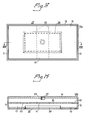
- Figures 13 and 14 are a horizontal projection and a vertical sectional view respectively of a device 10b according to the invention provided with an acoustic port 38 which is resistively ' snatched to the chamber 16 and the oscillatory member 14 directed towards the sound-source, which member can be provided in the manner illustrated with a dynamic damping arrangement 27, substantially in accordance with that illustrated in Figures 4 and 5.
- the port 38 is carried by a defining wall 15 opposing the oscillatory member 14.
- the wall 15 should be substantially passive to oscillations, have a relatively high density, and may be acoustically absorbing.
- the purpose of the port 38 is to influence the sound-absorbing characteristic of the device 10b in such a manner that said characteristic mainly occurs for sound acting on the oscillatory member 14 only and absorption takes place with an angular characteristic which substantially approaches cardioid-shape. Consequently, as a result of this arrangement, absorption at incident angles which are large in relation to the direction of oscillation of the member 14 is greatly improved, and the oscillatory member 14 obtains good resistive damping properties, since the angle-controlling port 38 opposes sound radiation therefrom, through its acoustic positioning and as a result of the presence of the acoustic resistance 39 in the mouth of the port facing the surroundings.
- the port 38 should be given such a large area that the resonance frequency of the port with the volume in chamber 16 substantially exceeds the acoustic resonance frequency which the same device would have had in the absence of port 38.
- a port area of about 2.5 dm 2 a port resonance frequency of about 70 Hz, the area of port 38 being about half the total original area of the member 15.
- the acoustic resistance in port 38 should act in the mouth of said port and should be so adjusted that the resonance frequency of the device 10b with the port 38 exhibiting resistance 39 is restored to approximately the resonance frequency of an equivalent device which lacks the arrangement 38, 39.
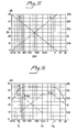
- Figure 15 is a diagram of a frequency spectrum having a 50 dB of dynamic-range and with the lower limit frequency set to 20 Hz. It is presumed in the diagram that the sound pressure level is constant when the frequency varies. In this way there is obtained the illustrated relationship between the amplitude A of the soundwave (full line) and its acceleration level a (broken line), where the slope of respective functions constitute 6 dB/octave. The geometric mean frequency of the spectrum is obtained at the point where the functions intersect, i.e. at 360 Hz.
- the acceleration level moves towards zero when the amplitude level moves towards infinity, and that the amplitude is greater than the acceleration of the soundwave in the frequency range where frequency decreases from 360 Hz, and that the acceleration is greater than the amplitude in the frequency range where the frequency increases from 360 Hz. If a frequency spectrum having a higher limit frequency than 20 Hz is considered, the mean-frequency point will lie at an even higher frequency. In the frequency range where amplitude dominates, the oscillation amplitude of an absorbing surface must also increase with 6 dB/octave when the frequency decreases - i.e. is doubled with each halving of the frequency - in order for absorption at the surface to be constant.
- the linear vibration amplitude at the absorption surface it must be possible for the linear vibration amplitude at the absorption surface to be progressively greater the lower the limit frequency (resonance frequency) for which the device is constructed.
- the mechanical resonance frequency of the oscillatory member in free air must then lie somewhat lower in frequency, e.g. at 20 Hz, in order for the spring force represented by the volume parameter of the device to be able to increase the mechanical resonance frequency in relation to the mechanical compliance of the oscillatory member and the spring stiffness of the air, and so that the resultant acoustic resonance frequency lies at 40 Hz.
- f is the acoustical re- a a sonance frequency
- f mech the mechanical resonance frequency
- s is the compliance ratio related to volume parameter V b .
- Q reaches 1.0 an acoustically closed circuit (resonance frequency substantially determined by a pressure function) is optimally dampened, this value being difficult to achieve in practice.
- Figure 16 illustrates theoretically different functions for an acoustically absorbing system in accordance with the invention.
- the totally obtained acoustic absorption (full line); to the left is shown by a broken line the oscillation function ⁇ vibr. ; and to the right is shown by a chain line the resistive absorption function ⁇ fric .
- a mineral fibre absorbent 14 used in the device 10 and having, for example, a staple fibre surface layer and a core having a thickness of about 20 mm and a density of about 20 kgm -3 .
- the resonance frequency f a of the absorbent and said volume may lie at about 50 Hz as illustrated in the Figure.
- the absorption function of the member 14 can be considered to be represented by a range of 100 % absorption which extends from about 1000 Hz, f fr , to about 4000 Hz, f fc , when the absorbent is measured without an air gap in a conventional manner in a reverberation chamber.
- an oscillation circuit and a resistive circuit there is obtained individually in the device an oscillation circuit and a resistive circuit, the effects of which are combined in a frequency range which extends from 50 Hz to 1 kHz, where both the functions are decreasing.
- the absorption will decrease by about 12 dB/octave.
- the absorption will increase by about 3 dB, to be constant in a perfect system up to 4 kHz, where it again decreases.
- the inductive absorption for the system may reach to maximally 100 % and lies at the resonance frequency 50 Hz. Neither can the resistive absorption ever be greater than 100 %, as is the case between 1000 Hz.and 4000 Hz.
- the absorption device according to the invention constitutes a substantially matched acoustic impedance, and hence resultant absorption of acoustic energy must always exceed the absorption which resistively prevails for the used oscillatory member 14 alone, and in the outlined case is greater than 100 % for frequencies which lie between 50 Hz (resonance frequency for the system) and the resistive cut-off frequency 4 kHz, which is marked as a section of 3 dB increased level at the top of Figure 16, and which, in practice, may reach to about twice the absorption applicable to the oscillatory member 14 itself.
- the oscillatory surface is doubled and the resultant absorption can increase by about 2 - 4 times the oscillatory surface used, as a result of acoustic coupling between the mutually opposing members 14, 15.
- the acoustic resonance frequency is approximately halved at the same volume parameter as that for a single design, due to the fact that one of the masses (member 14) loads the other of said masses (member 15) through the coupling effected via the air located in chamber 16.
- the described construction principles provide a wide variation in frequency range, absorption direction, corrections for angular incident sound energy and extremely good amplitude linearity, this last mentioned having very great significance in order to avoid undesirable secondary effects such as, for example, geneiating distortion components, random sound and troublesome acoustic reflexes.
- the devices according to the invention have an extremely fast pulse- response and offer but slight obstruction to propagation of the soundwave adjacent their oscillatory members, whereby direct reflections are efficiently suppressed and the acoustical damping effect becomes extremely high, particularly with respect to transient sound.
- differential systems are particularly suitable for use in general regulation of roan-acoustics and for noise damping in a very wide frequency range even with a high content of powerful transient noise in the low frequency range, since the differential systems absorb from both sides and exhibit particularly high acoustical damping effect.
- a particularly advantageous characteristic of the invention is its good reproducability, the possibility to use modular formats, and an insertion effect which is substantially additive and enables much higher total damping in a given room and in a much wider frequency range than that which can be achieved with conventional absorption constructions.
Landscapes
- Physics & Mathematics (AREA)
- Engineering & Computer Science (AREA)
- Acoustics & Sound (AREA)
- Multimedia (AREA)
- Building Environments (AREA)
- Soundproofing, Sound Blocking, And Sound Damping (AREA)
- Fittings On The Vehicle Exterior For Carrying Loads, And Devices For Holding Or Mounting Articles (AREA)
- Vehicle Interior And Exterior Ornaments, Soundproofing, And Insulation (AREA)
Applications Claiming Priority (2)
| Application Number | Priority Date | Filing Date | Title |
|---|---|---|---|
| SE8200624 | 1982-02-03 | ||
| SE8200624A SE8200624L (sv) | 1982-02-03 | 1982-02-03 | Akustisk anordning |
Publications (2)
| Publication Number | Publication Date |
|---|---|
| EP0086184A2 true EP0086184A2 (fr) | 1983-08-17 |
| EP0086184A3 EP0086184A3 (fr) | 1984-05-02 |
Family
ID=20345913
Family Applications (1)
| Application Number | Title | Priority Date | Filing Date |
|---|---|---|---|
| EP83850021A Withdrawn EP0086184A3 (fr) | 1982-02-03 | 1983-01-28 | Dispositif d'amortissement sonore |
Country Status (10)
| Country | Link |
|---|---|
| EP (1) | EP0086184A3 (fr) |
| JP (1) | JPS59500116A (fr) |
| AU (1) | AU1223383A (fr) |
| CA (1) | CA1198375A (fr) |
| DK (1) | DK435883A (fr) |
| FI (1) | FI840850A7 (fr) |
| NO (1) | NO833509L (fr) |
| SE (1) | SE8200624L (fr) |
| WO (1) | WO1983002793A1 (fr) |
| ZA (1) | ZA83591B (fr) |
Cited By (4)
| Publication number | Priority date | Publication date | Assignee | Title |
|---|---|---|---|---|
| GB2251719A (en) * | 1990-10-15 | 1992-07-15 | Wilhams Insulations Ltd | Acoustic baffle |
| EP0521740A1 (fr) * | 1991-04-25 | 1993-01-07 | Hutchinson | Matériau de protection acoustique et dispositif incorporant un tel matériau |
| US5241512A (en) * | 1991-04-25 | 1993-08-31 | Hutchinson 2 | Acoustic protection material and apparatus including such material |
| EP3750326A1 (fr) * | 2018-02-06 | 2020-12-16 | Artnovion, Lda | Absorbeur acoustique pour absorber un son de basse ou de sous-basse |
Family Cites Families (10)
| Publication number | Priority date | Publication date | Assignee | Title |
|---|---|---|---|---|
| DE732630C (de) * | 1937-04-04 | 1943-03-08 | Lufttechnische Ges M B H | Vorrichtung zur Geraeuschminderung in Leitungen |
| FR1198880A (fr) * | 1958-02-14 | 1959-12-10 | Chausson Usines Sa | Procédé et dispositif pour l'absorption des ondes sonores des appareils vibrants |
| GB932521A (en) * | 1961-06-01 | 1963-07-31 | Ferranti Ltd | Improvements relating to noise reducing enclosures |
| US3831710A (en) * | 1973-01-24 | 1974-08-27 | Lockheed Aircraft Corp | Sound absorbing panel |
| DE2360519C3 (de) * | 1973-12-05 | 1978-04-06 | Hermann Hemscheidt Maschinenfabrik Gmbh & Co, 5600 Wuppertal | Schallschutz-Wandelement |
| DE2451520C2 (de) * | 1974-10-30 | 1982-10-21 | Gerd Dieter 7326 Heiningen Maibach | Lärmschutzelement |
| FR2300384A1 (fr) * | 1975-02-07 | 1976-09-03 | Lockheed Aircraft Corp | Absorbeur acoustique a double bande |
| GB1499882A (en) * | 1975-02-14 | 1978-02-01 | Rolls Royce | Sound attenuating structure |
| DE2645484C2 (de) * | 1976-10-08 | 1978-07-27 | Volmer Betonwerk Gmbh & Co Kg, 4100 Duisburg | Betonstein für den Aufbau von Schallschutzwänden |
| DE3032269A1 (de) * | 1980-08-27 | 1982-04-08 | Hoechst Ag, 6000 Frankfurt | Resonatorschallabsorptionselement |
-
1982
- 1982-02-03 SE SE8200624A patent/SE8200624L/ not_active Application Discontinuation
-
1983
- 1983-01-28 JP JP58500695A patent/JPS59500116A/ja active Pending
- 1983-01-28 FI FI840850A patent/FI840850A7/fi not_active Application Discontinuation
- 1983-01-28 EP EP83850021A patent/EP0086184A3/fr not_active Withdrawn
- 1983-01-28 WO PCT/SE1983/000031 patent/WO1983002793A1/fr not_active Ceased
- 1983-01-28 ZA ZA83591A patent/ZA83591B/xx unknown
- 1983-01-28 AU AU12233/83A patent/AU1223383A/en not_active Abandoned
- 1983-02-02 CA CA000420794A patent/CA1198375A/fr not_active Expired
- 1983-09-23 DK DK435883A patent/DK435883A/da not_active Application Discontinuation
- 1983-09-28 NO NO833509A patent/NO833509L/no unknown
Cited By (4)
| Publication number | Priority date | Publication date | Assignee | Title |
|---|---|---|---|---|
| GB2251719A (en) * | 1990-10-15 | 1992-07-15 | Wilhams Insulations Ltd | Acoustic baffle |
| EP0521740A1 (fr) * | 1991-04-25 | 1993-01-07 | Hutchinson | Matériau de protection acoustique et dispositif incorporant un tel matériau |
| US5241512A (en) * | 1991-04-25 | 1993-08-31 | Hutchinson 2 | Acoustic protection material and apparatus including such material |
| EP3750326A1 (fr) * | 2018-02-06 | 2020-12-16 | Artnovion, Lda | Absorbeur acoustique pour absorber un son de basse ou de sous-basse |
Also Published As
| Publication number | Publication date |
|---|---|
| SE8200624L (sv) | 1983-08-04 |
| WO1983002793A1 (fr) | 1983-08-18 |
| ZA83591B (en) | 1983-11-30 |
| DK435883D0 (da) | 1983-09-23 |
| FI840850A0 (fi) | 1984-03-02 |
| EP0086184A3 (fr) | 1984-05-02 |
| NO833509L (no) | 1983-09-28 |
| FI840850L (fi) | 1984-03-02 |
| FI840850A7 (fi) | 1984-03-02 |
| JPS59500116A (ja) | 1984-01-19 |
| AU1223383A (en) | 1983-08-25 |
| CA1198375A (fr) | 1985-12-24 |
| DK435883A (da) | 1983-09-23 |
Similar Documents
| Publication | Publication Date | Title |
|---|---|---|
| Furstoss et al. | Surface impedance control for sound absorption: direct and hybrid passive/active strategies | |
| US4714133A (en) | Method and apparatus for augmentation of sound by enhanced resonance | |
| JP5167751B2 (ja) | 吸音構造 | |
| JPH11220789A (ja) | 電気音響変換装置 | |
| JP3027824B2 (ja) | 騒音及び振動防止用能動発泡プラスチック | |
| US10482865B2 (en) | Vibration damped sound shield | |
| JP5493378B2 (ja) | 吸音構造体 | |
| JP2012073472A (ja) | 吸音体 | |
| US20020046901A1 (en) | Noise cancellation using a mechanical oscillator | |
| US6778673B1 (en) | Tunable active sound absorbers | |
| EP0086184A2 (fr) | Dispositif d'amortissement sonore | |
| JPH0823753B2 (ja) | 消音装置 | |
| US6130951A (en) | Speaker having multiple sound bodies and multiple sound openings | |
| US6173805B1 (en) | Variably tuned vibration absorber | |
| KR100323794B1 (ko) | 유체감쇠식음향인클로우저시스템 | |
| CN114783400B (zh) | 一种并联弹簧振子吸声结构 | |
| JP2009293251A (ja) | 吸音構造、吸音構造群、音響室及び騒音低減方法 | |
| US7440580B2 (en) | Room mode bass absorption through combined diaphragmatic and helmholtz resonance techniques | |
| WO2019181614A1 (fr) | Cellule d'insonorisation et structure d'insonorisation faisant appel à ladite cellule | |
| US2718932A (en) | Loud speaker construction | |
| JP3288513B2 (ja) | 吸音体 | |
| WO1984002940A1 (fr) | Dispositif pour systemes acoustiques | |
| JPS62266012A (ja) | 吸音パ−テイシヨン | |
| JP2015026932A (ja) | スピーカーの消音性振動板ユニット | |
| JPH04194244A (ja) | 吸音材 |
Legal Events
| Date | Code | Title | Description |
|---|---|---|---|
| PUAI | Public reference made under article 153(3) epc to a published international application that has entered the european phase |
Free format text: ORIGINAL CODE: 0009012 |
|
| AK | Designated contracting states |
Designated state(s): AT BE CH DE FR GB IT LI LU NL SE |
|
| PUAL | Search report despatched |
Free format text: ORIGINAL CODE: 0009013 |
|
| AK | Designated contracting states |
Designated state(s): AT BE CH DE FR GB IT LI LU NL SE |
|
| 17P | Request for examination filed |
Effective date: 19841024 |
|
| STAA | Information on the status of an ep patent application or granted ep patent |
Free format text: STATUS: THE APPLICATION IS DEEMED TO BE WITHDRAWN |
|
| 18D | Application deemed to be withdrawn |
Effective date: 19860408 |