EP0086200B1 - Optische bestimmung von oberflächenprofilen - Google Patents
Optische bestimmung von oberflächenprofilen Download PDFInfo
- Publication number
- EP0086200B1 EP0086200B1 EP19820902344 EP82902344A EP0086200B1 EP 0086200 B1 EP0086200 B1 EP 0086200B1 EP 19820902344 EP19820902344 EP 19820902344 EP 82902344 A EP82902344 A EP 82902344A EP 0086200 B1 EP0086200 B1 EP 0086200B1
- Authority
- EP
- European Patent Office
- Prior art keywords
- shape
- image
- profile
- light
- datum
- Prior art date
- Legal status (The legal status is an assumption and is not a legal conclusion. Google has not performed a legal analysis and makes no representation as to the accuracy of the status listed.)
- Expired
Links
- 230000003287 optical effect Effects 0.000 title claims description 13
- 238000000034 method Methods 0.000 claims abstract description 36
- 230000009466 transformation Effects 0.000 claims abstract description 25
- 229910000831 Steel Inorganic materials 0.000 claims abstract description 11
- 239000010959 steel Substances 0.000 claims abstract description 11
- 238000012545 processing Methods 0.000 claims abstract description 7
- 238000005286 illumination Methods 0.000 claims description 15
- 230000001131 transforming effect Effects 0.000 claims description 9
- 230000007246 mechanism Effects 0.000 claims description 7
- 230000008859 change Effects 0.000 claims description 6
- 238000005259 measurement Methods 0.000 description 10
- 230000008569 process Effects 0.000 description 7
- 238000004519 manufacturing process Methods 0.000 description 5
- 238000000844 transformation Methods 0.000 description 4
- 230000005855 radiation Effects 0.000 description 3
- 238000004458 analytical method Methods 0.000 description 2
- 238000003491 array Methods 0.000 description 2
- 238000003384 imaging method Methods 0.000 description 2
- 238000007689 inspection Methods 0.000 description 2
- 239000013307 optical fiber Substances 0.000 description 2
- 238000005096 rolling process Methods 0.000 description 2
- 238000010561 standard procedure Methods 0.000 description 2
- 238000013519 translation Methods 0.000 description 2
- 241000196324 Embryophyta Species 0.000 description 1
- 240000000731 Fagus sylvatica Species 0.000 description 1
- 235000010099 Fagus sylvatica Nutrition 0.000 description 1
- 230000001427 coherent effect Effects 0.000 description 1
- 239000000109 continuous material Substances 0.000 description 1
- 239000006185 dispersion Substances 0.000 description 1
- 238000006073 displacement reaction Methods 0.000 description 1
- 230000000694 effects Effects 0.000 description 1
- 230000005670 electromagnetic radiation Effects 0.000 description 1
- 230000008030 elimination Effects 0.000 description 1
- 238000003379 elimination reaction Methods 0.000 description 1
- 239000011521 glass Substances 0.000 description 1
- 238000010348 incorporation Methods 0.000 description 1
- 238000002955 isolation Methods 0.000 description 1
- 238000005304 joining Methods 0.000 description 1
- 239000011159 matrix material Substances 0.000 description 1
- 239000002184 metal Substances 0.000 description 1
- 238000012986 modification Methods 0.000 description 1
- 230000004048 modification Effects 0.000 description 1
- 238000012544 monitoring process Methods 0.000 description 1
- 238000003672 processing method Methods 0.000 description 1
- 238000007493 shaping process Methods 0.000 description 1
- 238000001228 spectrum Methods 0.000 description 1
Images


Classifications
-
- G—PHYSICS
- G01—MEASURING; TESTING
- G01B—MEASURING LENGTH, THICKNESS OR SIMILAR LINEAR DIMENSIONS; MEASURING ANGLES; MEASURING AREAS; MEASURING IRREGULARITIES OF SURFACES OR CONTOURS
- G01B11/00—Measuring arrangements characterised by the use of optical techniques
- G01B11/02—Measuring arrangements characterised by the use of optical techniques for measuring length, width or thickness
- G01B11/024—Measuring arrangements characterised by the use of optical techniques for measuring length, width or thickness by means of diode-array scanning
Definitions
- the present invention relates to a method of, an apparatus for, providing information as to the cross-sectional shape or the profile of a body (such as steel bars or railway wheels), or for measuring the cross-sectional dimensions thereof.
- a body such as steel bars or railway wheels
- the shape or profile of the body may be compared to pre-established dimensional standards and/or the information obtained may be supplied to a forming or shaping apparatus so that a closed loop control of a forming process can be achieved.
- the object of this invention it to provide a method and apparatus for providing information as to the cross-sectional shape or profile of the body which remove geometric distortions due to viewing geometry and thus enables accurate determination of the required information without the need for or reliance on rigid control of the geometry of the system.
- reference in this specification to the provision of information as to the cross-sectional shape or profile of the body includes information relating to the dimensions of the body, shape and relative location of the body. It should also be understood that reference to light in this specification includes non-visible as well as visible parts of the electromagnetic radiation spectrum. It should also be understood that reference to steel bars or metal bar in this specification includes rolled or extruded sections such as channel, angle, railway line and the like.
- the present invention may be said to reside in a method of determining the cross sectional shape or profile of at least a portion of a surface of a body comprising:
- Distortion caused by the viewing geometry of the sensor means will distort the datum. Accordingly the transformation of the preliminary information concerning the body in accordance with the variation between the detected datum and the known datum will compensate for that distortion so that more accurate information as to the cross-sectional shape or profile of the body will be obtained.
- Image distortions introduced by the viewing geometry include those that can be classified as perspective, rotation, and scaling distortions. These can all be compensated for by the incorporation and imaging of a suitably designed datum.
- any slight change in the geometry of the apparatus of the present invention will likewise be compensated for by the transformation of the preliminary information in accordance with the variation of the detected datum from the known datum.
- an accurate representation of the profile of the body can be displayed on a video screen. If the information required is the cross-sectional dimension of the body, this may readily be obtained by suitable processing means from the accurate representations of the body.
- the present invention is also quite suitable for use in providing information in respect of a body which is in relative motion to the measuring system althought it will be appreciated that the invention is applicable to situations where the body and system are both stationary.
- the datum consists of a plurality of protrusions or a plurality of illuminated reference points and the sensor means comprises at least one camera, each or the camera being able to view at least four datum points which do not lie in a straight line.
- the preferred embodiment of the invention also provides that a number of sensor means be arranged around the body to provide several part images from multiple illumination means so that the part images may be combined and aligned by means of the datum to reconstruct a complete cross-sectional profile of the body.
- Figure 1 shows a slit illumination technique which can be embodied in the present invention
- a slit light source 10 (which may include a laser) is shown which illuminates a steel bar 12 with a planar beam of light.
- the light is diffusely reflected from the steel bar and received by a camera 14 which is connected to an image processing computer 16 and a numeric and graphic output device 40 such as a video screen.
- a numeric and graphic output device 40 such as a video screen.
- a number of illuminated reference points 20 are applied to a guide mechanism 50 ( Figure 2) through which the rolled steel bar 12, for example, passes at a measurement station.
- the reference points 20 are arranged to lie as near as possible in the same plane as the multiple slit illumination sources, and the physical relationships between the reference points 20 is precisely controlled and fixed at the guide manufacturing stage.
- the reference points are arranged so that at least three are visible to each sensor (camera 14) when viewing a part image of the bar.
- at least four reference points must be visible to each camera during a calibration phase prior to the measurement process. Such calibration may be performed when there is no bar 12 in the guide mechanism 50.
- each camera 14 is precisely located on the corners of a square whose side dimension is slightly greater than the largest object which has to pass through the guide 50.
- a greater number of reference points may be required if more than one camera 14 is to be used, as in the embodiment of Figure 5, and each camera 14 views only a small section of the complete profile, to ensure that each camera 14 views at least three reference points 20 (which must not be in a straight line) during the measurement process and at least four reference points during the calibration process.
- each camera 14 receives an image containing one or more continuous sections consisting of arrays of bright picture elements or pixels representing the partial profile of the bar 12 being measured, plus at least three groups of bright pixels each representing a reference point 20.
- each pixel is assigned a two dimensional (X,Y) address related to its location on the sensor array of each camera 14.
- the geometric centre of each reference point can therefore be determined electronically by consideration of the X,Y addresses assigned to individual pixels forming the image of each reference point 20. Consequently the apparent geometric relationship between the image of the reference points 20 can be determined.
- the image detected by each camera 14 will be three reference points 20'and portion 12'of the profile of bar 12. After suitable transformation of the images of the reference points 20' to new values 20" which conform with the true of physical relationship of the points 20 on guide 50 and the same transformation is applied to portion 12' a true image 12" of the profile of the bar 12 is obtained. Excess pixels of this image may be removed by standard techniques to provide a clearer indication of the true contour on video screen 40.
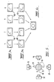
- each camera sees a different set of the three reference images labeled A to D in Figure 5.
- the processing of the images seen by each camera follows the steps of removing excess pixels, transformation, and joining ends in that order.
- the processing includes a transformation as described above and a rotation.
- the centres of the images of points A to D seen by each camera are transformed to conform with the true or physical relationship of the points 20 ( Figure 5A).
- the images are then rotated ( Figure 5B) so that the reference points A to D are in the same position on screen 40 and the images from each camera 14 are then combined (Figure 5C) to form the true image of the profile of bar 12.
- One preferred imaging transformation which may be utilized in the invention is as follows: wherein the x ⁇ etc. are the homogeneous image coordination and the x o etc. are the coordinates of a point in object space. The true image points are then given by
- the matrix P defines the nonlinear perspective transformation.
- L defines the translation from the lens coordinates to the sensor image plane coordinates and T defines the translation from the object coordinate frame to the lens coordinate frame.
- the matrices R 1' R 2 , R 3 define the angular displacements of the camera system from the object coordinate frame and are used to correct for pan, tilt and rotation of the camera with respect to the object frame.
- the source of illumination for the object may be a laser. This is particularly desirable when measuring a hot body which emits visible and infra red radiation which interferes with the externally applied illumination.
- the use of lasers permits the use of very selective optical filters at the sensor array or arrays to eliminate most of the background visible or infra red radiation while passing the diffusely reflected laser light with minimum attenuation. In this situation it is essential that the source of illumination for the reference points also be laser of the same wavelength as those used for the body illumination so that the reference point radiation will also pass through the optical filters.
- optical fibers to transmit the light from a remotely mounted laser 60 to form each of the reference points.
- this embodiment use is made of bundles 62 of very fine glass threads which are packaged together to create an optical fibre bundle 64. Four such bundles are joined together at one end 65 and illuminated by a common laser 60 remote from the guide assembly 50 ( Figure 2) via a lens 61.
- each of the four small bundles are individually polished and mounted so as to protrude from the front face of the guide in the field of view of the cameras 14, and close to the plane of illumination of the slit projecting lasers (light source 10).
- the laser light thus emitted from the ends 60 of the polished fibres forms the reference point sources directly.
- Miniature lenses could be fitted to the ends of the fibres if special dispersion characteristics are required.
- Figure 7 shows an alternative manner of forming the reference points.
- a ring 84 is provided with four screw thread holes 86.
- the ring 84 is connected to the outlet of a guide member, similar to that shown in Figure 2, by any suitable means such as bolts which pass thorugh openings 88 in the ring.
- the four threaded holes 86 each receive a pin 90 which has a screw threaded shank 92 for allowing the pins 90 to be screwed into holes 86.
- the protrusion 94 forming the outer portion of each pin 90 is of small circular cross-section.
- Lasers 10 (only one shown in Figure 7) are arranged to project a thin beam of light across the protrusions 94.
- the display obtained by a suitable arranged camera is shown in Figure 7A.
- the illuminated protrusions 94 appear as small arcs 96, and the bar which passes through the ring 84 appears as a crescent 98 as in the previously described embodiment.
- the centre of curvature of arcs 96 can be determined by standard techniques to give the position of the reference points, being at the centre of protrusions 94.
- the holes 86 could be drilled into the bar guide itself in the positions of the points 20 in Figure 2 and the pins 90 could be screwed directly into the guide shown in Figure 2.
- the protrusions 94 are utilized it is not necessary to provide the guide with the optical fibres previously described.
- Figure 8 is a schematic view of an embodiment of the invention applied to monitoring the wear surface a railway wheel from a track side mounted measuring station as the railway wheels pass the measuring station.
- the rail 70 has a frame member 72 arranged thereunder on which four reference points 74 are located.
- the reference points 74 may be formed in any of the ways described above.
- a planar light source 76 is arranged beside the rail 70 to illuminate the wear surface, comprising the tread inside flange and root areas, of the wheel 80 with a thin beam of light so that camera 78 views the line 82, projected onto the wear surface of the wheel 80, along with three of the reference points 74.
- the reference point technique proposed here is seen as a means of overcoming the limitations of existing profile measurement by slit illumination techniques. Specifically, the technique enables the determination of the size, shape and location of either a part orthe complete surface profile of an object to a high degree of accuracy without the need for precise and frequent alignment or vibration isolation of the sensing devices.
Landscapes
- Physics & Mathematics (AREA)
- General Physics & Mathematics (AREA)
- Length Measuring Devices By Optical Means (AREA)
Claims (19)
Priority Applications (1)
| Application Number | Priority Date | Filing Date | Title |
|---|---|---|---|
| AT82902344T ATE58966T1 (de) | 1981-08-14 | 1982-08-12 | Optische bestimmung von oberflaechenprofilen. |
Applications Claiming Priority (2)
| Application Number | Priority Date | Filing Date | Title |
|---|---|---|---|
| AUPF025781 | 1981-08-14 | ||
| AU257/81 | 1981-08-14 |
Publications (3)
| Publication Number | Publication Date |
|---|---|
| EP0086200A1 EP0086200A1 (de) | 1983-08-24 |
| EP0086200A4 EP0086200A4 (de) | 1988-05-19 |
| EP0086200B1 true EP0086200B1 (de) | 1990-12-05 |
Family
ID=3769164
Family Applications (1)
| Application Number | Title | Priority Date | Filing Date |
|---|---|---|---|
| EP19820902344 Expired EP0086200B1 (de) | 1981-08-14 | 1982-08-12 | Optische bestimmung von oberflächenprofilen |
Country Status (5)
| Country | Link |
|---|---|
| EP (1) | EP0086200B1 (de) |
| JP (1) | JPS58501290A (de) |
| CA (1) | CA1186505A (de) |
| DE (1) | DE3280272D1 (de) |
| WO (1) | WO1983000738A1 (de) |
Families Citing this family (21)
| Publication number | Priority date | Publication date | Assignee | Title |
|---|---|---|---|---|
| AU571673B2 (en) * | 1984-03-09 | 1988-04-21 | Onesteel Manufacturing Pty Limited | Optical article measuring system |
| ZA851768B (en) * | 1984-03-09 | 1985-11-27 | Broken Hill Pty Co Ltd | Calibration method |
| KR940007111B1 (ko) * | 1985-06-14 | 1994-08-05 | 더브로큰 힐 프로프라이어터리 컴패니 리미티드 | 물체의 단면형상 및 윤곽의 측정방법 및 장치 |
| DE3526923A1 (de) * | 1985-07-27 | 1987-02-05 | Man Technologie Gmbh | Verfahren und einrichtung zur beruehrungslosen bestimmung von oberflaechen |
| IT1215102B (it) * | 1986-10-28 | 1990-01-31 | Zanussi Zeltron Inst | Procedimento per l'ispezione automatica di piastre canalizzate |
| IT1211500B (it) * | 1987-11-05 | 1989-11-03 | Fiat Auto Spa | Metodo e apparecchiatura per effettuare il controllo dimensionale di un pezzo per via optoelettronica |
| FR2641607B1 (fr) * | 1989-01-06 | 1993-12-31 | Electricite De France | Systeme de releve de la surface d'une piece a distance par un capteur optique, notamment d'un auget de turbine pelton |
| CA1319513C (en) * | 1989-01-11 | 1993-06-29 | Darwin H. Isdahl | Apparatus and method for measuring and maintaining the profile of a railroad track rail |
| JP2758810B2 (ja) * | 1992-10-15 | 1998-05-28 | 株式会社ミツトヨ | 形状測定方法 |
| EP0617254A1 (de) * | 1993-03-25 | 1994-09-28 | Wilhelm Hegenscheidt Gesellschaft mbH | Verfahren und Einrichtung zur Dickenbestimmung an Radkränzen oder Bandagen von Rädern von Eisenbahnradsätzen |
| US5500737A (en) * | 1993-07-21 | 1996-03-19 | General Electric Company | Method for measuring the contour of a surface |
| EP0699890A1 (de) * | 1994-08-02 | 1996-03-06 | General Electric Company | Apparat zum Messen der Kontur einer Oberfläche |
| US6931149B2 (en) * | 2002-04-19 | 2005-08-16 | Norsk Elektro Optikk A/S | Pipeline internal inspection device and method |
| DE10313191A1 (de) | 2003-03-25 | 2004-10-07 | Gutehoffnungshütte Radsatz Gmbh | Verfahren zur berührungslosen dynamischen Erfassung des Profils eines Festkörpers |
| NZ525129A (en) * | 2003-10-03 | 2006-09-29 | Bruce Peter Parker | An improved transformation method for creating pre-distorted images to event surfaces of televised events |
| CN2849715Y (zh) * | 2005-11-29 | 2006-12-20 | 上海铁路局科学技术研究所 | 一种非接触式ccd高速动态检测装置 |
| IT1399094B1 (it) * | 2010-03-26 | 2013-04-05 | Tenova Spa | Metodo e sistema di rilevamento e di determinazione di caratteristiche geometriche, dimensionali e posizionali di prodotti trasportati da un trasportatore continuo, in particolare prodotti siderurgici grezzi, sgrossati, sbozzati o semilavorati. |
| ITUB20155673A1 (it) * | 2015-11-18 | 2017-05-18 | Gd Spa | Unita di ispezione di un elemento allungato. |
| ITUB20155646A1 (it) * | 2015-11-18 | 2017-05-18 | Gd Spa | Metodo di ispezione di un elemento allungato. |
| ITUB20160002A1 (it) * | 2016-01-27 | 2017-07-27 | Gd Spa | Metodo ed unità di ispezione di un elemento allungato. |
| JP6795060B1 (ja) * | 2019-07-11 | 2020-12-02 | オムロン株式会社 | 制御装置およびこれを備えたレーザ加工システム、レーザ加工方法 |
Family Cites Families (7)
| Publication number | Priority date | Publication date | Assignee | Title |
|---|---|---|---|---|
| US3854822A (en) * | 1973-06-27 | 1974-12-17 | Vsi Corp | Electro-optical scanning system for dimensional gauging of parts |
| DE2412359A1 (de) * | 1974-03-14 | 1975-09-25 | Dornier System Gmbh | Verfahren und geraet zur beruehrungslosen vermessung von objektkonturen |
| DE2514930A1 (de) * | 1975-04-05 | 1976-10-14 | Opto Produkte Ag | Verfahren zur optischen ermittlung und zum vergleich von formen und lagen von objekten |
| US4269513A (en) * | 1975-08-27 | 1981-05-26 | Solid Photography Inc. | Arrangement for sensing the surface of an object independent of the reflectance characteristics of the surface |
| FR2344814A1 (fr) * | 1976-03-18 | 1977-10-14 | Fievet Eric | Procede de releves topographiques pour ausculter et mesurer des ouvrages ou objets, et materiel utilise |
| US4246606A (en) * | 1979-04-17 | 1981-01-20 | Hajime Industries Ltd. | Inspection apparatus |
| DE2920634A1 (de) * | 1979-05-22 | 1981-05-27 | Philipp Dr.med. Dr.rer.nat. 8000 München Deisler | Verfahren zur beruehrungslosen vermessung von koerpern |
-
1982
- 1982-08-12 DE DE8282902344T patent/DE3280272D1/de not_active Expired - Lifetime
- 1982-08-12 JP JP57502438A patent/JPS58501290A/ja active Pending
- 1982-08-12 EP EP19820902344 patent/EP0086200B1/de not_active Expired
- 1982-08-12 WO PCT/AU1982/000129 patent/WO1983000738A1/en not_active Ceased
- 1982-08-16 CA CA000409525A patent/CA1186505A/en not_active Expired
Also Published As
| Publication number | Publication date |
|---|---|
| CA1186505A (en) | 1985-05-07 |
| DE3280272D1 (de) | 1991-01-17 |
| EP0086200A4 (de) | 1988-05-19 |
| EP0086200A1 (de) | 1983-08-24 |
| WO1983000738A1 (en) | 1983-03-03 |
| JPS58501290A (ja) | 1983-08-04 |
Similar Documents
| Publication | Publication Date | Title |
|---|---|---|
| EP0086200B1 (de) | Optische bestimmung von oberflächenprofilen | |
| CA1320548C (en) | Non-contact determination of the position of a rectilinear feature of an article | |
| US11199395B2 (en) | Profile inspection system for threaded and axial components | |
| CA1307051C (en) | Method and apparatus for monitoring the surface profile of a moving workpiece | |
| US5619587A (en) | System and method for contactlessly gauging the thickness of a contoured object, such as a vehicle wheel | |
| CA2278332C (en) | Optoelectronic system using spatiochromatic triangulation | |
| US6268923B1 (en) | Optical method and system for measuring three-dimensional surface topography of an object having a surface contour | |
| US6392754B1 (en) | Method and apparatus for measuring the profile of reflective surfaces | |
| US4776692A (en) | Testing light transmitting articles | |
| EP0419936B1 (de) | Verfahren und Vorrichtung zur Phasenmessung von Strahlung, insbesondere Lichtstrahlung | |
| US5661671A (en) | Bending angle detecting position setting device | |
| US5999265A (en) | System for measuring gap and mismatch between opposing parts | |
| US5090811A (en) | Optical radius gauge | |
| EP0502930A1 (de) | Verfahren und anordnung zur optoelektronischen vermessung von gegenständen. | |
| EP1999447B1 (de) | Vorrichtung und verfahren zum prüfen eines reifens | |
| DE4235832A1 (de) | Dachoberflaechenmessvorrichtung | |
| US4710808A (en) | Machine vision differential measurement system | |
| DE102004033526A1 (de) | Verfahren und Vorrichtung zur Analyse zumindest partiell reflektierender Oberflächen | |
| DE69314829T2 (de) | Krümmungsmessung einer Oberfläche | |
| US5206703A (en) | Method of and apparatus for measuring small gaps | |
| EP0502162B1 (de) | Moire distanzmessungen mit einem aus objekt fixiertem oder aufgedrucktem raster | |
| AU8763882A (en) | Measurement method and apparatus | |
| Toenshoff et al. | Use of Fresnel diffraction for the measurement of rotational symmetrical workpieces | |
| JPH03199946A (ja) | 透視歪の測定方法及びその装置 | |
| Arizaga et al. | Digital technique for high accuracy focal length measurements |
Legal Events
| Date | Code | Title | Description |
|---|---|---|---|
| PUAI | Public reference made under article 153(3) epc to a published international application that has entered the european phase |
Free format text: ORIGINAL CODE: 0009012 |
|
| PUAI | Public reference made under article 153(3) epc to a published international application that has entered the european phase |
Free format text: ORIGINAL CODE: 0009012 |
|
| 17P | Request for examination filed |
Effective date: 19830325 |
|
| AK | Designated contracting states |
Designated state(s): AT BE CH DE FR GB LI LU NL SE |
|
| A4 | Supplementary search report drawn up and despatched |
Effective date: 19880519 |
|
| 17Q | First examination report despatched |
Effective date: 19890522 |
|
| GRAA | (expected) grant |
Free format text: ORIGINAL CODE: 0009210 |
|
| AK | Designated contracting states |
Kind code of ref document: B1 Designated state(s): AT BE CH DE FR GB LI LU NL SE |
|
| PG25 | Lapsed in a contracting state [announced via postgrant information from national office to epo] |
Ref country code: NL Effective date: 19901205 Ref country code: LI Effective date: 19901205 Ref country code: CH Effective date: 19901205 Ref country code: BE Effective date: 19901205 |
|
| REF | Corresponds to: |
Ref document number: 58966 Country of ref document: AT Date of ref document: 19901215 Kind code of ref document: T |
|
| ET | Fr: translation filed | ||
| REF | Corresponds to: |
Ref document number: 3280272 Country of ref document: DE Date of ref document: 19910117 |
|
| REG | Reference to a national code |
Ref country code: CH Ref legal event code: PL |
|
| NLV1 | Nl: lapsed or annulled due to failure to fulfill the requirements of art. 29p and 29m of the patents act | ||
| PLBI | Opposition filed |
Free format text: ORIGINAL CODE: 0009260 |
|
| PLAB | Opposition data, opponent's data or that of the opponent's representative modified |
Free format text: ORIGINAL CODE: 0009299OPPO |
|
| 26 | Opposition filed |
Opponent name: FIRMA WIDMANN BILDVERARBEITUNGSSYSTEME OHG Effective date: 19910805 |
|
| R26 | Opposition filed (corrected) |
Opponent name: FIRMA WIDMANN BILDVERARBEITUNGSSYSTEME OHG Effective date: 19910805 |
|
| EPTA | Lu: last paid annual fee | ||
| PLBN | Opposition rejected |
Free format text: ORIGINAL CODE: 0009273 |
|
| STAA | Information on the status of an ep patent application or granted ep patent |
Free format text: STATUS: OPPOSITION REJECTED |
|
| 27O | Opposition rejected |
Effective date: 19940619 |
|
| EAL | Se: european patent in force in sweden |
Ref document number: 82902344.9 |
|
| PGFP | Annual fee paid to national office [announced via postgrant information from national office to epo] |
Ref country code: GB Payment date: 19980803 Year of fee payment: 17 |
|
| PGFP | Annual fee paid to national office [announced via postgrant information from national office to epo] |
Ref country code: SE Payment date: 19980806 Year of fee payment: 17 |
|
| PGFP | Annual fee paid to national office [announced via postgrant information from national office to epo] |
Ref country code: AT Payment date: 19980813 Year of fee payment: 17 |
|
| PGFP | Annual fee paid to national office [announced via postgrant information from national office to epo] |
Ref country code: FR Payment date: 19980814 Year of fee payment: 17 |
|
| PGFP | Annual fee paid to national office [announced via postgrant information from national office to epo] |
Ref country code: LU Payment date: 19980819 Year of fee payment: 17 |
|
| PGFP | Annual fee paid to national office [announced via postgrant information from national office to epo] |
Ref country code: DE Payment date: 19980821 Year of fee payment: 17 |
|
| PG25 | Lapsed in a contracting state [announced via postgrant information from national office to epo] |
Ref country code: LU Free format text: LAPSE BECAUSE OF NON-PAYMENT OF DUE FEES Effective date: 19990812 Ref country code: GB Free format text: LAPSE BECAUSE OF NON-PAYMENT OF DUE FEES Effective date: 19990812 Ref country code: AT Free format text: LAPSE BECAUSE OF NON-PAYMENT OF DUE FEES Effective date: 19990812 |
|
| PG25 | Lapsed in a contracting state [announced via postgrant information from national office to epo] |
Ref country code: SE Free format text: THE PATENT HAS BEEN ANNULLED BY A DECISION OF A NATIONAL AUTHORITY Effective date: 19990830 |
|
| GBPC | Gb: european patent ceased through non-payment of renewal fee |
Effective date: 19990812 |
|
| PG25 | Lapsed in a contracting state [announced via postgrant information from national office to epo] |
Ref country code: FR Free format text: LAPSE BECAUSE OF NON-PAYMENT OF DUE FEES Effective date: 20000428 |
|
| EUG | Se: european patent has lapsed |
Ref document number: 82902344.9 |
|
| PG25 | Lapsed in a contracting state [announced via postgrant information from national office to epo] |
Ref country code: DE Free format text: LAPSE BECAUSE OF NON-PAYMENT OF DUE FEES Effective date: 20000601 |
|
| REG | Reference to a national code |
Ref country code: FR Ref legal event code: ST |
|
| PLAB | Opposition data, opponent's data or that of the opponent's representative modified |
Free format text: ORIGINAL CODE: 0009299OPPO |