EP0086247A1 - Elektropneumatischer Signalwandler - Google Patents
Elektropneumatischer Signalwandler Download PDFInfo
- Publication number
- EP0086247A1 EP0086247A1 EP82101149A EP82101149A EP0086247A1 EP 0086247 A1 EP0086247 A1 EP 0086247A1 EP 82101149 A EP82101149 A EP 82101149A EP 82101149 A EP82101149 A EP 82101149A EP 0086247 A1 EP0086247 A1 EP 0086247A1
- Authority
- EP
- European Patent Office
- Prior art keywords
- nozzle
- flapper
- core
- pressure
- signal
- Prior art date
- Legal status (The legal status is an assumption and is not a legal conclusion. Google has not performed a legal analysis and makes no representation as to the accuracy of the status listed.)
- Granted
Links
- 230000005291 magnetic effect Effects 0.000 claims abstract description 32
- 239000003302 ferromagnetic material Substances 0.000 claims abstract description 16
- 230000001419 dependent effect Effects 0.000 claims abstract description 7
- 230000004075 alteration Effects 0.000 claims description 7
- 230000005294 ferromagnetic effect Effects 0.000 claims description 5
- 238000013016 damping Methods 0.000 claims description 3
- 230000000694 effects Effects 0.000 claims description 3
- 239000003989 dielectric material Substances 0.000 claims description 2
- 239000002184 metal Substances 0.000 description 9
- 229910052751 metal Inorganic materials 0.000 description 9
- 239000011248 coating agent Substances 0.000 description 2
- 238000000576 coating method Methods 0.000 description 2
- 230000001276 controlling effect Effects 0.000 description 2
- 238000009434 installation Methods 0.000 description 2
- 229910001369 Brass Inorganic materials 0.000 description 1
- RYGMFSIKBFXOCR-UHFFFAOYSA-N Copper Chemical compound [Cu] RYGMFSIKBFXOCR-UHFFFAOYSA-N 0.000 description 1
- 239000004411 aluminium Substances 0.000 description 1
- 229910052782 aluminium Inorganic materials 0.000 description 1
- XAGFODPZIPBFFR-UHFFFAOYSA-N aluminium Chemical compound [Al] XAGFODPZIPBFFR-UHFFFAOYSA-N 0.000 description 1
- 230000015572 biosynthetic process Effects 0.000 description 1
- 239000010951 brass Substances 0.000 description 1
- 238000010276 construction Methods 0.000 description 1
- 239000010949 copper Substances 0.000 description 1
- 229910052802 copper Inorganic materials 0.000 description 1
- 230000003111 delayed effect Effects 0.000 description 1
- 238000010586 diagram Methods 0.000 description 1
- 239000000975 dye Substances 0.000 description 1
- 238000004043 dyeing Methods 0.000 description 1
- 230000004907 flux Effects 0.000 description 1
- 238000004519 manufacturing process Methods 0.000 description 1
- 230000010355 oscillation Effects 0.000 description 1
- 239000004033 plastic Substances 0.000 description 1
- 229920003023 plastic Polymers 0.000 description 1
- 230000036632 reaction speed Effects 0.000 description 1
- 230000001105 regulatory effect Effects 0.000 description 1
- 239000010979 ruby Substances 0.000 description 1
- 229910001750 ruby Inorganic materials 0.000 description 1
- 230000035945 sensitivity Effects 0.000 description 1
- 125000006850 spacer group Chemical group 0.000 description 1
Images

Classifications
-
- G—PHYSICS
- G05—CONTROLLING; REGULATING
- G05D—SYSTEMS FOR CONTROLLING OR REGULATING NON-ELECTRIC VARIABLES
- G05D16/00—Control of fluid pressure
- G05D16/20—Control of fluid pressure characterised by the use of electric means
- G05D16/2006—Control of fluid pressure characterised by the use of electric means with direct action of electric energy on controlling means
- G05D16/2013—Control of fluid pressure characterised by the use of electric means with direct action of electric energy on controlling means using throttling means as controlling means
-
- G—PHYSICS
- G01—MEASURING; TESTING
- G01D—MEASURING NOT SPECIALLY ADAPTED FOR A SPECIFIC VARIABLE; ARRANGEMENTS FOR MEASURING TWO OR MORE VARIABLES NOT COVERED IN A SINGLE OTHER SUBCLASS; TARIFF METERING APPARATUS; MEASURING OR TESTING NOT OTHERWISE PROVIDED FOR
- G01D5/00—Mechanical means for transferring the output of a sensing member; Means for converting the output of a sensing member to another variable where the form or nature of the sensing member does not constrain the means for converting; Transducers not specially adapted for a specific variable
- G01D5/42—Mechanical means for transferring the output of a sensing member; Means for converting the output of a sensing member to another variable where the form or nature of the sensing member does not constrain the means for converting; Transducers not specially adapted for a specific variable using fluid means
- G01D5/44—Mechanical means for transferring the output of a sensing member; Means for converting the output of a sensing member to another variable where the form or nature of the sensing member does not constrain the means for converting; Transducers not specially adapted for a specific variable using fluid means using jets of fluid
Definitions
- the invention relates to an electro-pneumatic signal converter for converting an electric current signal into a pneumatic pressure signal, comprising a force-balancing system in which a magnetic force is balanced against a pneumatic force.
- Signal converters of the kind indicated above are known where the current which is to be converted flows through a coil suspended in a magnetic field caused by a permanent magnet.
- the forces developed by the current and the magnetic field tend to push the coil out of the magnetic field.
- the force is compared, by a balance beam which is movable in a spring band cross, with the force which is developed in a bellows connected to the balance beam. If these forces are not alike, the position of the beam is altered.
- the new position is converted in a nozzle into a pneumatic pressure which acts on an upper diaphragm in a pneumatic amplifier belonging to the device.
- the device also includes a number of further components and functions which will not be described in more detail here.
- a futher limitation of conventional electro-pneumatic signal converters is that they cannot use a working pressure of 4 - 6 bar, which is the prevalent working pressure in industry, without converters.
- the object of the invention is to eliminate the abovementioned limitations and disadvantages in conventional electro-pneumatic converters. More specifically, it is an object to offer an converter with very few movable parts, small space requirements, extremely satisfactory tolerance of vibration, satisfactory possibilities for balancing out and, inter alia, very high speed of reaction, and with satisfactory possibilities for achieving the optimum between hysteresis and transfer characteristics.
- the signal converter comprises, in combination, a coil through which the electrical signal current flows; a magnetic curcuit comprising a core of ferromagnetic material disposed in the coil with a nozzle chamber with a mouth in the form of a nozzle at one end of the core, a flapper of ferromagnetic material over the nozzle and a link of ferromagnetic material which closes the magnetic circuit between the flapper and the opposite end of the core; a feed line for a constant flow of feed air into the nozzle chamber and out again through the nozzle; and a pressure-sensing line from the nozzle chamber to a pressuredependent member to supply a pneumatic pressure signal from the nozzle chamber to the pressure-dependent member.
- the feed air is conveyed into the nozzle chamber from a pressure source at a constant speed.
- the pressure source may consist, for example, of a driving air source at 4 to 6 bar of the kind which is normal in industry.
- a throttle is provided in the entry passage so that the air flows into the nozzle chamber at sonic speed. From the nozzle chamber, the air flows out again through the nozzle into the gap between the outh of the nozzle and the flapper. In the course of this, the air acts with an upwardly directed force on the flapper.
- the current signal which is flowing through the coil generates a magnetic field in the core which acts through a downward force on the flapper.
- the flapper therefore comes to assume different positions so that the pneumatic and magnetic forces which are acting on the flapper balance one another.
- the size of the air gap between the nozzle and the flap varies which in turn acts on the pressure in the nozzle and in the nozzle chamber.
- the pressure and the variations in pressure are supplied via a pressure sensing line to the pressure-sensing member which the aim is to influence.
- the damper consists of a body of electrically conducting, non-ferromagnetic material which surrounds the ferromagnetic core in the region before the end which is adjacent to the flapper, which body acts as a short-circuit turn in which a current is induced caused by alterations in the current in the coil which generates a magnetic field in the core which is oppositely directed to the field generated in the coil by the current and which has a damping effect on the movements of the flapper.
- the air gap between the flapper and the nozzle is very small, every alteration in the size of the air gap has a very powerful effect on the air pressure while the magnetic field, on the other hand, is influenced comparatively little.
- This is preferably effected as a result of the fact that the flapper is provided at its under side, that is to say at the side which is adjacent to the nozzle, with a coating or plate of non-ferromagnetic, preferably dielectric material, which prevents short-circuiting of the magnetic circuit between the core and the flapper.
- This plate or coating may appropriately be given a thickness between 0.1 and 0.5 mm, the thickness being selected depending on the other dimensions of the signal converter.
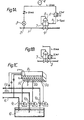
- the control equipment shown diagrammatically in Fig. 1A is adapted to regulate the flow in a pipeline 1.
- the flow in the pipe 1 is measured at a measuring point 2 and generates a pressure signal which is converted into a current signal in a pressure-current converter, a so-called pressure transmitter 3.
- the actual value from the pressure transmitter 3 is treated in a regulator 4 with setting of the guide value.
- the regulator 4 delivers a setting value in the form of a signal current of 4 - 20 mA to a electro-pneumatic, so-called IP converter 5.
- the IP converter 5 is fed with driving air from a standard pressure source of 6 bar.
- a pneumatic pressure signal is obtained which is supplied, via a pressure line 6, to a so-called positioner 7 which controls a setting device 8 for setting the flap in a flap valve 9 in the pipeline 1 so that the desired flow is obtained in the pipe.
- FIG. 1A illustrates an arrangement which is very common in conventional installations, where the IP converter has to be placed at a distance from the positioner in view of the space requirements of the converter but often also because of the sensitivity of conventional IP converters to vibration.
- the IP converter according to the invention can also be disposed in the manner shown in Fig. 1A.
- the invention provides great possibilities for placing the IP converter directly on the positioner 7, as illustrated in Fig. 1B, since the converter requires very little space and at the same time is extremely tolerant of vibrations.
- the small space requirements also make it possible, in practice, to dispose a large number of IP converters in a centre connected to a computer for controlling a large industrial plant.
- the pipes 1A, 1B and 1C can be assumed to constitute pipes for dyes which are to be mixed in a dyeing bath 10.
- the three IP converters 5A, 5B and 5C which are included in a large battery of converters connected to a computer 11, are coupled to the respective positioners to regulate the flow in the pipes 1A - 1B by controlling the respective flap valves 9A - C.
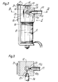
- the construction of the electro-pneumatic converter 5 - the IP converter - is shown in Fig. 2 and 3.
- the arrangement comprises a coil 11 on a core 12 of ferromagnetic material.
- the core 12 extends past the upper end of the coil 11 and becomes narrower in its uppermost portion where a nozzle 13 with a nozzle chamber 14 is disposed, Fig. 3.
- a nozzle is understood to mean the mouth of the nozzle chamber.
- the core 12 is surrounded by a body 15 of electrically conducting but non-ferromagnetic material, for example brass, copper, aluminium or the like metal.
- the metal body 15 has a square horizontal section and is firmly screwed to a bracket 16 of ferromagnetic material of the same kind as the core 12.
- a flapper 17 Disposed above the nozzle 13 is a flapper 17 which is also made of the same ferromagnetic material as the bracket 16 and the core 12.
- the flapper 17 is articulately mounted on the upper end of the bracket 16 and comprises a balance 21.
- the core 12, the bracket 16 and the flapper 17 form a magnetic circuit for the magnetic field which is generated by the current in the coil 11.
- a current signal must flow through the coil 11.
- the washer 18 has a thickness of 0.25 mm according to the form of embodiment.
- a feed pipe 19 for driving air Connected to the chamber 14 is a feed pipe 19 for driving air.
- the driving air is introduced through the metal body 15, that is to say in the radial direction towards the chamber 14.
- the core 12 may be produced, for example, from a length of tubing.
- the infeed conduit through the metal body 15 is designated by the numeral 19A and its continuation in the wall of the core 12 by the numeral 19B.
- a throttle 23 Disposed in the feed conduit 19A in the metal body 15 is a throttle 23 in the form of drilled-out ruby, so that the air which passes through the conduit 19B into the chamber flows into the chamber 14 at sonic speed, which guarantees a constant flow of air.
- a pressure sensing passage 22 leads via a pressure sensing pipe 6 to the pressure-dependent member, for example a positioner, which is to be acted upon by the variations in pressure in the nozzle chamber 14.
- the gap between the nozzle 13 and the washer 18 at the under side of the flapper is designated by 25.
- the device thus described works in the following manner.
- a current signal through the coil 11 generates a mangetic field in the core 12.
- the magnetic field tends to pull the flapper 17 in the downward direction.
- the air pressure is altered in the nozzle 13 and hence in the nozzle chamber 14.
- the pressure in the nozzle thus influences the flapper in the upward direction so that the downwardly directed magnetic force and the upwardly directed pneumatic pressure force balance on another.
- Variations in pressure in the nozzle chamber 14 are detected by the pressure sensing passage 22 leading into the nozzle chamber and are transmitted via the pressure line 24 to the pressure-dependent member.
- the reaction speed of the device is very high.
- the metal body 15 is provided. Currents are actually induced in the metal body 15 which generate an oppositely directed magnetic field in the core 12 when the current signal in the coil 11 is altered.
- Fig. 5 illustrates the magnetic circuit, the longer arrows symbolizing the magnetic field which is generated by the coil 11, while the shorter arrows illustrate the oppositely directed field which is generated by the current which is induced in the metal body 15 as a result of alterations in the signal current.
- the metal body 15 affords a suitable damping in the system, and the washer 18 prevents the thickness of the gap 25 from approaching zero.
- the flapper 17 is prevented from oscillating when the flapper is in its lowest position, where every alteration couses very great alterations in the air pressure whereas the magnetic flux is influenced comparatively little.
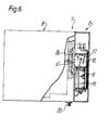
- Fig. 6 illustrates how an IP converter 5 according to the invention, as a result of its handy format and vibration-tolerant formation, can be advantageously connected directly to a positioner 7 and a setting device 8 so that from these elements, an integrated unit 21 is obtained with small external dimensions.
- the unit 21 is fed with driving air to a common connection 20 from where driving air is obtained on the one hand for the setting device 8 and on the other hand for the IP converter 5.
- a pressure signal is obtained which is transmitted via the directly coupled pressure-signal connection 6 to the pressure-sensitive diaphragm 26 of the positioner 7 so as to influence the setting device 8 in the desired manner in a known manner in the following parts.
Landscapes
- Physics & Mathematics (AREA)
- Fluid Mechanics (AREA)
- General Physics & Mathematics (AREA)
- Engineering & Computer Science (AREA)
- Automation & Control Theory (AREA)
- Supply Devices, Intensifiers, Converters, And Telemotors (AREA)
- Transmission And Conversion Of Sensor Element Output (AREA)
- Measurement Of Radiation (AREA)
- Control Of Eletrric Generators (AREA)
- Magnetically Actuated Valves (AREA)
Priority Applications (3)
| Application Number | Priority Date | Filing Date | Title |
|---|---|---|---|
| EP82101149A EP0086247B1 (de) | 1982-02-17 | 1982-02-17 | Elektropneumatischer Signalwandler |
| AT82101149T ATE29584T1 (de) | 1982-02-17 | 1982-02-17 | Elektropneumatischer signalwandler. |
| DE8282101149T DE3277234D1 (en) | 1982-02-17 | 1982-02-17 | Electropneumatic signal converter |
Applications Claiming Priority (1)
| Application Number | Priority Date | Filing Date | Title |
|---|---|---|---|
| EP82101149A EP0086247B1 (de) | 1982-02-17 | 1982-02-17 | Elektropneumatischer Signalwandler |
Publications (2)
| Publication Number | Publication Date |
|---|---|
| EP0086247A1 true EP0086247A1 (de) | 1983-08-24 |
| EP0086247B1 EP0086247B1 (de) | 1987-09-09 |
Family
ID=8188877
Family Applications (1)
| Application Number | Title | Priority Date | Filing Date |
|---|---|---|---|
| EP82101149A Expired EP0086247B1 (de) | 1982-02-17 | 1982-02-17 | Elektropneumatischer Signalwandler |
Country Status (3)
| Country | Link |
|---|---|
| EP (1) | EP0086247B1 (de) |
| AT (1) | ATE29584T1 (de) |
| DE (1) | DE3277234D1 (de) |
Cited By (1)
| Publication number | Priority date | Publication date | Assignee | Title |
|---|---|---|---|---|
| EP0370667A3 (de) * | 1988-11-21 | 1991-07-03 | Bellofram Corporation | Strom-Druckwandler mit verbesserten Leistungsmerkmalen |
Citations (2)
| Publication number | Priority date | Publication date | Assignee | Title |
|---|---|---|---|---|
| GB507359A (en) * | 1938-03-21 | 1939-06-14 | Siemens Brothers & Co Ltd | Improvements relating to electromagnetic relays |
| US2975976A (en) * | 1957-05-31 | 1961-03-21 | Vapor Heating Corp | Electro pneumatic temperature control system |
Family Cites Families (1)
| Publication number | Priority date | Publication date | Assignee | Title |
|---|---|---|---|---|
| DE3015980A1 (de) * | 1980-04-25 | 1981-11-05 | Honeywell B.V., Amsterdam | Gasdruckregler |
-
1982
- 1982-02-17 EP EP82101149A patent/EP0086247B1/de not_active Expired
- 1982-02-17 AT AT82101149T patent/ATE29584T1/de active
- 1982-02-17 DE DE8282101149T patent/DE3277234D1/de not_active Expired
Patent Citations (2)
| Publication number | Priority date | Publication date | Assignee | Title |
|---|---|---|---|---|
| GB507359A (en) * | 1938-03-21 | 1939-06-14 | Siemens Brothers & Co Ltd | Improvements relating to electromagnetic relays |
| US2975976A (en) * | 1957-05-31 | 1961-03-21 | Vapor Heating Corp | Electro pneumatic temperature control system |
Cited By (1)
| Publication number | Priority date | Publication date | Assignee | Title |
|---|---|---|---|---|
| EP0370667A3 (de) * | 1988-11-21 | 1991-07-03 | Bellofram Corporation | Strom-Druckwandler mit verbesserten Leistungsmerkmalen |
Also Published As
| Publication number | Publication date |
|---|---|
| DE3277234D1 (en) | 1987-10-15 |
| EP0086247B1 (de) | 1987-09-09 |
| ATE29584T1 (de) | 1987-09-15 |
Similar Documents
| Publication | Publication Date | Title |
|---|---|---|
| US7503342B2 (en) | Proportional directional control valve with a magnetic positioning sensor | |
| US4481967A (en) | Control circuit for current to pressure converter | |
| US6079435A (en) | Current to pressure converter | |
| US4325399A (en) | Current to pressure converter apparatus | |
| US5257639A (en) | Electropneumatic positioner | |
| US4855659A (en) | Electropneumatic position regulator | |
| US5678601A (en) | Compact controller for control valve | |
| JPH06501138A (ja) | 電空式ポジショナー | |
| US6708715B2 (en) | Pneumatic pressure control device | |
| US4907615A (en) | High frequency response servovalve with electrical position feedback element structure and method | |
| US3811465A (en) | Electric-fluidic direct proportion converter | |
| US4442854A (en) | Electro-pneumatic signal converter | |
| EP0086247A1 (de) | Elektropneumatischer Signalwandler | |
| US2842147A (en) | Force responsive devices | |
| SE420639B (sv) | Signalomvandlare enhet for omvandling av en elektrisk reglersignal till en pneumatisk signal med ett piezoelektrisk element | |
| US2780230A (en) | Pneumatic control apparatus with follow-up | |
| US3004546A (en) | Electro-pneumatic transducer | |
| US3221760A (en) | Dry coil servo valve | |
| US5770807A (en) | Apparatus for taking up and guiding a connection device | |
| US2980835A (en) | Mechanically rebalanced linear motor servosystem | |
| FI80507C (fi) | Transduktor foer omvandlande av elsignal till trycksignal. | |
| US4874005A (en) | Current to pressure tranducer employing magnetic fluid | |
| US4821760A (en) | Voice coil assembly for an electropneumatic converter | |
| GB1572584A (en) | Electro-pneumatic current-to-position transducer | |
| JPS5911766B2 (ja) | デジタル流体流れ制御装置 |
Legal Events
| Date | Code | Title | Description |
|---|---|---|---|
| PUAI | Public reference made under article 153(3) epc to a published international application that has entered the european phase |
Free format text: ORIGINAL CODE: 0009012 |
|
| PUAI | Public reference made under article 153(3) epc to a published international application that has entered the european phase |
Free format text: ORIGINAL CODE: 0009012 |
|
| AK | Designated contracting states |
Designated state(s): AT BE CH DE FR GB IT LI LU NL SE |
|
| 17P | Request for examination filed |
Effective date: 19831208 |
|
| GRAA | (expected) grant |
Free format text: ORIGINAL CODE: 0009210 |
|
| AK | Designated contracting states |
Kind code of ref document: B1 Designated state(s): AT BE CH DE FR GB IT LI LU NL SE |
|
| PG25 | Lapsed in a contracting state [announced via postgrant information from national office to epo] |
Ref country code: AT Effective date: 19870909 |
|
| REF | Corresponds to: |
Ref document number: 29584 Country of ref document: AT Date of ref document: 19870915 Kind code of ref document: T |
|
| REF | Corresponds to: |
Ref document number: 3277234 Country of ref document: DE Date of ref document: 19871015 |
|
| ITF | It: translation for a ep patent filed | ||
| ET | Fr: translation filed | ||
| PLBE | No opposition filed within time limit |
Free format text: ORIGINAL CODE: 0009261 |
|
| STAA | Information on the status of an ep patent application or granted ep patent |
Free format text: STATUS: NO OPPOSITION FILED WITHIN TIME LIMIT |
|
| 26N | No opposition filed | ||
| ITTA | It: last paid annual fee | ||
| EPTA | Lu: last paid annual fee | ||
| EAL | Se: european patent in force in sweden |
Ref document number: 82101149.1 |
|
| PGFP | Annual fee paid to national office [announced via postgrant information from national office to epo] |
Ref country code: SE Payment date: 20001228 Year of fee payment: 20 |
|
| PGFP | Annual fee paid to national office [announced via postgrant information from national office to epo] |
Ref country code: DE Payment date: 20010212 Year of fee payment: 20 |
|
| PGFP | Annual fee paid to national office [announced via postgrant information from national office to epo] |
Ref country code: LU Payment date: 20010213 Year of fee payment: 20 Ref country code: FR Payment date: 20010213 Year of fee payment: 20 Ref country code: CH Payment date: 20010213 Year of fee payment: 20 |
|
| PGFP | Annual fee paid to national office [announced via postgrant information from national office to epo] |
Ref country code: GB Payment date: 20010214 Year of fee payment: 20 |
|
| PGFP | Annual fee paid to national office [announced via postgrant information from national office to epo] |
Ref country code: NL Payment date: 20010228 Year of fee payment: 20 |
|
| PGFP | Annual fee paid to national office [announced via postgrant information from national office to epo] |
Ref country code: BE Payment date: 20010427 Year of fee payment: 20 |
|
| BE20 | Be: patent expired |
Free format text: 20020217 A.B. *SOMAS VENTILER |
|
| REG | Reference to a national code |
Ref country code: GB Ref legal event code: IF02 |
|
| PG25 | Lapsed in a contracting state [announced via postgrant information from national office to epo] |
Ref country code: LI Free format text: LAPSE BECAUSE OF EXPIRATION OF PROTECTION Effective date: 20020216 Ref country code: GB Free format text: LAPSE BECAUSE OF EXPIRATION OF PROTECTION Effective date: 20020216 Ref country code: CH Free format text: LAPSE BECAUSE OF EXPIRATION OF PROTECTION Effective date: 20020216 |
|
| PG25 | Lapsed in a contracting state [announced via postgrant information from national office to epo] |
Ref country code: NL Free format text: LAPSE BECAUSE OF EXPIRATION OF PROTECTION Effective date: 20020217 Ref country code: LU Free format text: LAPSE BECAUSE OF EXPIRATION OF PROTECTION Effective date: 20020217 |
|
| REG | Reference to a national code |
Ref country code: GB Ref legal event code: PE20 Effective date: 20020216 |
|
| REG | Reference to a national code |
Ref country code: CH Ref legal event code: PL |
|
| EUG | Se: european patent has lapsed |
Ref document number: 82101149.1 |
|
| NLV7 | Nl: ceased due to reaching the maximum lifetime of a patent |