EP0086332A1 - Circuit pour fluide sous pression particulièrement pour barre de coupe - Google Patents
Circuit pour fluide sous pression particulièrement pour barre de coupe Download PDFInfo
- Publication number
- EP0086332A1 EP0086332A1 EP83100225A EP83100225A EP0086332A1 EP 0086332 A1 EP0086332 A1 EP 0086332A1 EP 83100225 A EP83100225 A EP 83100225A EP 83100225 A EP83100225 A EP 83100225A EP 0086332 A1 EP0086332 A1 EP 0086332A1
- Authority
- EP
- European Patent Office
- Prior art keywords
- pressure medium
- line
- pressure
- flow
- control valve
- Prior art date
- Legal status (The legal status is an assumption and is not a legal conclusion. Google has not performed a legal analysis and makes no representation as to the accuracy of the status listed.)
- Granted
Links
- 239000012530 fluid Substances 0.000 title abstract 4
- 230000001105 regulatory effect Effects 0.000 abstract 1
- 230000008878 coupling Effects 0.000 description 4
- 238000010168 coupling process Methods 0.000 description 4
- 238000005859 coupling reaction Methods 0.000 description 4
- 230000007935 neutral effect Effects 0.000 description 3
- 230000002411 adverse Effects 0.000 description 1
- 238000007599 discharging Methods 0.000 description 1
Images
Classifications
-
- F—MECHANICAL ENGINEERING; LIGHTING; HEATING; WEAPONS; BLASTING
- F15—FLUID-PRESSURE ACTUATORS; HYDRAULICS OR PNEUMATICS IN GENERAL
- F15B—SYSTEMS ACTING BY MEANS OF FLUIDS IN GENERAL; FLUID-PRESSURE ACTUATORS, e.g. SERVOMOTORS; DETAILS OF FLUID-PRESSURE SYSTEMS, NOT OTHERWISE PROVIDED FOR
- F15B11/00—Servomotor systems without provision for follow-up action; Circuits therefor
- F15B11/16—Servomotor systems without provision for follow-up action; Circuits therefor with two or more servomotors
-
- A—HUMAN NECESSITIES
- A01—AGRICULTURE; FORESTRY; ANIMAL HUSBANDRY; HUNTING; TRAPPING; FISHING
- A01D—HARVESTING; MOWING
- A01D34/00—Mowers; Mowing apparatus of harvesters
- A01D34/01—Mowers; Mowing apparatus of harvesters characterised by features relating to the type of cutting apparatus
- A01D34/412—Mowers; Mowing apparatus of harvesters characterised by features relating to the type of cutting apparatus having rotating cutters
- A01D34/63—Mowers; Mowing apparatus of harvesters characterised by features relating to the type of cutting apparatus having rotating cutters having cutters rotating about a vertical axis
- A01D34/76—Driving mechanisms for the cutters
- A01D34/80—Driving mechanisms for the cutters fluid
-
- F—MECHANICAL ENGINEERING; LIGHTING; HEATING; WEAPONS; BLASTING
- F15—FLUID-PRESSURE ACTUATORS; HYDRAULICS OR PNEUMATICS IN GENERAL
- F15B—SYSTEMS ACTING BY MEANS OF FLUIDS IN GENERAL; FLUID-PRESSURE ACTUATORS, e.g. SERVOMOTORS; DETAILS OF FLUID-PRESSURE SYSTEMS, NOT OTHERWISE PROVIDED FOR
- F15B2211/00—Circuits for servomotor systems
- F15B2211/30—Directional control
- F15B2211/31—Directional control characterised by the positions of the valve element
- F15B2211/3105—Neutral or centre positions
- F15B2211/3116—Neutral or centre positions the pump port being open in the centre position, e.g. so-called open centre
-
- F—MECHANICAL ENGINEERING; LIGHTING; HEATING; WEAPONS; BLASTING
- F15—FLUID-PRESSURE ACTUATORS; HYDRAULICS OR PNEUMATICS IN GENERAL
- F15B—SYSTEMS ACTING BY MEANS OF FLUIDS IN GENERAL; FLUID-PRESSURE ACTUATORS, e.g. SERVOMOTORS; DETAILS OF FLUID-PRESSURE SYSTEMS, NOT OTHERWISE PROVIDED FOR
- F15B2211/00—Circuits for servomotor systems
- F15B2211/30—Directional control
- F15B2211/31—Directional control characterised by the positions of the valve element
- F15B2211/3122—Special positions other than the pump port being connected to working ports or the working ports being connected to the return line
- F15B2211/3127—Floating position connecting the working ports and the return line
-
- F—MECHANICAL ENGINEERING; LIGHTING; HEATING; WEAPONS; BLASTING
- F15—FLUID-PRESSURE ACTUATORS; HYDRAULICS OR PNEUMATICS IN GENERAL
- F15B—SYSTEMS ACTING BY MEANS OF FLUIDS IN GENERAL; FLUID-PRESSURE ACTUATORS, e.g. SERVOMOTORS; DETAILS OF FLUID-PRESSURE SYSTEMS, NOT OTHERWISE PROVIDED FOR
- F15B2211/00—Circuits for servomotor systems
- F15B2211/30—Directional control
- F15B2211/31—Directional control characterised by the positions of the valve element
- F15B2211/3138—Directional control characterised by the positions of the valve element the positions being discrete
-
- F—MECHANICAL ENGINEERING; LIGHTING; HEATING; WEAPONS; BLASTING
- F15—FLUID-PRESSURE ACTUATORS; HYDRAULICS OR PNEUMATICS IN GENERAL
- F15B—SYSTEMS ACTING BY MEANS OF FLUIDS IN GENERAL; FLUID-PRESSURE ACTUATORS, e.g. SERVOMOTORS; DETAILS OF FLUID-PRESSURE SYSTEMS, NOT OTHERWISE PROVIDED FOR
- F15B2211/00—Circuits for servomotor systems
- F15B2211/40—Flow control
- F15B2211/405—Flow control characterised by the type of flow control means or valve
- F15B2211/40515—Flow control characterised by the type of flow control means or valve with variable throttles or orifices
-
- F—MECHANICAL ENGINEERING; LIGHTING; HEATING; WEAPONS; BLASTING
- F15—FLUID-PRESSURE ACTUATORS; HYDRAULICS OR PNEUMATICS IN GENERAL
- F15B—SYSTEMS ACTING BY MEANS OF FLUIDS IN GENERAL; FLUID-PRESSURE ACTUATORS, e.g. SERVOMOTORS; DETAILS OF FLUID-PRESSURE SYSTEMS, NOT OTHERWISE PROVIDED FOR
- F15B2211/00—Circuits for servomotor systems
- F15B2211/40—Flow control
- F15B2211/45—Control of bleed-off flow, e.g. control of bypass flow to the return line
-
- F—MECHANICAL ENGINEERING; LIGHTING; HEATING; WEAPONS; BLASTING
- F15—FLUID-PRESSURE ACTUATORS; HYDRAULICS OR PNEUMATICS IN GENERAL
- F15B—SYSTEMS ACTING BY MEANS OF FLUIDS IN GENERAL; FLUID-PRESSURE ACTUATORS, e.g. SERVOMOTORS; DETAILS OF FLUID-PRESSURE SYSTEMS, NOT OTHERWISE PROVIDED FOR
- F15B2211/00—Circuits for servomotor systems
- F15B2211/50—Pressure control
- F15B2211/505—Pressure control characterised by the type of pressure control means
- F15B2211/50554—Pressure control characterised by the type of pressure control means the pressure control means controlling a pressure downstream of the pressure control means, e.g. pressure reducing valve
-
- F—MECHANICAL ENGINEERING; LIGHTING; HEATING; WEAPONS; BLASTING
- F15—FLUID-PRESSURE ACTUATORS; HYDRAULICS OR PNEUMATICS IN GENERAL
- F15B—SYSTEMS ACTING BY MEANS OF FLUIDS IN GENERAL; FLUID-PRESSURE ACTUATORS, e.g. SERVOMOTORS; DETAILS OF FLUID-PRESSURE SYSTEMS, NOT OTHERWISE PROVIDED FOR
- F15B2211/00—Circuits for servomotor systems
- F15B2211/50—Pressure control
- F15B2211/515—Pressure control characterised by the connections of the pressure control means in the circuit
- F15B2211/5151—Pressure control characterised by the connections of the pressure control means in the circuit being connected to a pressure source and a directional control valve
-
- F—MECHANICAL ENGINEERING; LIGHTING; HEATING; WEAPONS; BLASTING
- F15—FLUID-PRESSURE ACTUATORS; HYDRAULICS OR PNEUMATICS IN GENERAL
- F15B—SYSTEMS ACTING BY MEANS OF FLUIDS IN GENERAL; FLUID-PRESSURE ACTUATORS, e.g. SERVOMOTORS; DETAILS OF FLUID-PRESSURE SYSTEMS, NOT OTHERWISE PROVIDED FOR
- F15B2211/00—Circuits for servomotor systems
- F15B2211/70—Output members, e.g. hydraulic motors or cylinders or control therefor
- F15B2211/78—Control of multiple output members
- F15B2211/781—Control of multiple output members one or more output members having priority
Definitions
- the invention relates to a pressure medium circuit, in particular for a mower on an agricultural tractor, with at least two consumers which can be actuated by a control slide and with a pressure medium pump which takes over its pressure medium supply and is connected with its pressure line directly to a three-way flow control valve, the outputs of which for one constant pressure medium flow and a residual flow are connected to two separate branches of the hydraulic circuit for supplying the pressure medium to the consumption associated therewith.
- the line carrying the constant current has no pressure limiting element.
- the pressure may rise in an impermissible manner as a short-term consumer when the cylinder is fully extended, which in the flow control valve leads to the residual current supplying the main consumer being reduced or completely interrupted.
- the invention has for its object to provide a pressure medium circuit of the type outlined at the outset, in which the constant current amount can be selected in the range of the given possibility and the pressure of the constant current is secured against inadmissible increase and in which the constant current is also activated when not switched on Is well used by consumers.
- the three-way flow control valve is adjustable with regard to the constant amount and that the line carrying the constant current has a pressure relief valve, the return line as well as the return lines of the control valve or valves located in constant current for the associated consumers with the Residual current in the other branch of the hydraulic circuit leading line is connected.
- the adjustability of the constant current quantity makes it possible to optionally operate one or more short-term consumers from the constant current, without endangering the supply of the main consumer operated by the residual current. It is also provided that the constant current quantity not required for short-term consumers is fed to the residual current quantity for supplying the main consumer.
- the pressure-limiting valve ensures that the pressure drop at the measuring orifice necessary for the control capability of the three-way flow control valve is always present by maintaining the current.
- the entire pump delivery is to the good utilization also flowing at the pressure relief valve portion of the pressure medium is also the residual current for powering the H auptver- brauchers fed again.
- the pressure path flow control valve forms a structural unit with the pressure limiting valve, in particular for space-saving reasons.
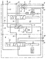
- the only figure shows schematically a hydraulic circuit according to the invention with a three-way flow control valve, a pressure relief valve for the constant flow and two control slides for the consumers to be connected.
- the hydraulic device is composed of several block elements 1, 2 and can be expanded as desired by adding further block elements.
- a multi-way slide 3 is arranged as a control slide, which can be fixed by a hydraulic catch 4 in the two switching positions outside the middle neutral position.
- two lines 5 and 6 lead via mutually influenced check valves 7 and 8 and via detachable hose couplings 9 and 10 to a main consumer, not shown, which can be designed, for example, as a hydraulic motor.
- the inflow of the pressure medium to the block element 1 from a pressure medium pump, not shown, is denoted by 12 and is connected by a line 13 to the input of a three-way flow control valve 14.
- a primary pressure relief valve Between the pressure medium pump and the inlet 12 is a primary pressure relief valve, also not shown, which controls the entire hydr. System safeguards.
- two lines 15 and 16 are connected to the flow control valve 14, of which line 15 is provided for a constant current and line 16 for a residual current.
- the line 16 discharging the residual current from the flow control valve 14 is connected to the multi-way slide valve 3 and also leads to the flange surface 17, which allows the connection of a further block element if required.
- the line 16 is connected at the connection 18 in a manner not shown to the reservoir for pressure medium, also not shown.
- a line 19 for the return of pressure medium is connected by a branching line 21 and an adjoining line 22 to the multi-way slide 3 or the hydraulic catch 4, leads outside the block elements 1 and 2 to the aforementioned storage container.
- the three-way flow control valve 14 is designed to be adjustable with regard to the constant current flowing through the outlet-side line 15, so that it can be adapted to the respective requirements within the given possibilities.
- the connection of only one consumer is provided, for which a multi-way slide 23 connected to the line 15 is arranged in the block element 2 as a control slide.
- This multi-way slide valve 23 is connected by two lines 24 and 25 and detachable hose couplings 26, 27 to the short-term consumer (not shown) and by line 19 to the return line.
- the arrangement is such that, when the multi-way slide valve 23 is in the neutral position shown, the line 15 brought up to it on the inlet side is connected downstream in the flow direction with a line 29 which, on the other hand, is connected to the line 16 carrying the residual current.
- a pressure limiting valve 30 is connected to line 15, the outflow line 31 of which is also connected to line 16.
- the multi-way slide 3 a connected to the hose connections 9 and 10 V ER- consumers, for example a hydraulic motor fed on, then it is supplied not only from the branched from the three-way flow control valve 14 remaining amount of the total flow, but also reaches the constant amount by the line 15, the multi-way slide valve 23 and line 29 into line 16, so that the total delivery volume is available to the main consumers connected to the hose couplings 9 and 10.
- the consumer connected to the hose couplings 26 and 27, for example a cylinder is activated by actuating the multi-way slide 23, the constant current is required to supply this consumer and is therefore not available to the main consumer for a short time.
- the pressure relief valve 30 ensures that simultaneous supply of H auptangeers and the constant-current load type for the function of the current regulator is maintained even with locked line 15, for example After the cylinder stroke.
Landscapes
- Engineering & Computer Science (AREA)
- Life Sciences & Earth Sciences (AREA)
- Environmental Sciences (AREA)
- Physics & Mathematics (AREA)
- Fluid Mechanics (AREA)
- Mechanical Engineering (AREA)
- General Engineering & Computer Science (AREA)
- Fluid-Pressure Circuits (AREA)
- Knives (AREA)
- Harvester Elements (AREA)
- Lifting Devices For Agricultural Implements (AREA)
Priority Applications (1)
| Application Number | Priority Date | Filing Date | Title |
|---|---|---|---|
| AT83100225T ATE13796T1 (de) | 1982-02-03 | 1983-01-13 | Druckmittelkreislauf, insbesondere fuer ein maehwerk. |
Applications Claiming Priority (2)
| Application Number | Priority Date | Filing Date | Title |
|---|---|---|---|
| DE3203465 | 1982-02-03 | ||
| DE19823203465 DE3203465A1 (de) | 1982-02-03 | 1982-02-03 | Druckmittelkreislauf, insbesondere fuer ein maehwerk |
Publications (2)
| Publication Number | Publication Date |
|---|---|
| EP0086332A1 true EP0086332A1 (fr) | 1983-08-24 |
| EP0086332B1 EP0086332B1 (fr) | 1985-06-19 |
Family
ID=6154579
Family Applications (1)
| Application Number | Title | Priority Date | Filing Date |
|---|---|---|---|
| EP83100225A Expired EP0086332B1 (fr) | 1982-02-03 | 1983-01-13 | Circuit pour fluide sous pression particulièrement pour barre de coupe |
Country Status (3)
| Country | Link |
|---|---|
| EP (1) | EP0086332B1 (fr) |
| AT (1) | ATE13796T1 (fr) |
| DE (2) | DE3203465A1 (fr) |
Cited By (4)
| Publication number | Priority date | Publication date | Assignee | Title |
|---|---|---|---|---|
| EP0772385A4 (fr) * | 1994-05-03 | 2000-08-16 | Hay & Forage Ind | Moissonneuse comportant une barre de coupe rotative actionnee par un systeme hydraulique a circuit de compensation de volume d'ecoulement |
| WO2009042143A1 (fr) * | 2007-09-24 | 2009-04-02 | Clark Equipment Company | Système de régulation de débit hydraulique auxiliaire pour un petit chargeur |
| DE102014111795A1 (de) * | 2014-08-19 | 2016-02-25 | Gisela Weber | Hydraulische Steuereinrichtung und Hydrauliksystem für ein Pressensystem aus hydraulischer Presse und Zuführeinrichtung |
| US20230092116A1 (en) * | 2021-09-17 | 2023-03-23 | Carl Geringhoff GmbH Co. KG | Switchable Cutter Bar Drive for Agricultural Attachment |
Families Citing this family (2)
| Publication number | Priority date | Publication date | Assignee | Title |
|---|---|---|---|---|
| DE3714666A1 (de) * | 1987-05-02 | 1988-11-10 | Kloeckner Humboldt Deutz Ag | Steueranlage fuer die arbeitshydraulik eines insbesondere land- und bauwirtschaftlich nutzbaren kraftfahrzeugs |
| DE3733371A1 (de) * | 1987-10-02 | 1989-04-13 | Kloeckner Humboldt Deutz Ag | Hydraulische steuereinrichtung fuer die arbeitshydraulik eines land- und bauwirtschaftlich nutzbaren fahrzeugs |
Citations (2)
| Publication number | Priority date | Publication date | Assignee | Title |
|---|---|---|---|---|
| DE7725445U1 (fr) * | Erwin Hengstler Fabrik Hydraulischer Hebezeuge, 7613 Hausach | |||
| DE1926894A1 (de) * | 1969-05-27 | 1970-12-03 | Kloeckner Humboldt Deutz Ag | Steuergeraet fuer einen hydraulischen Maehwerkantrieb und den Aushubzylinder des Messerbalkens |
Family Cites Families (5)
| Publication number | Priority date | Publication date | Assignee | Title |
|---|---|---|---|---|
| DE1185387B (de) * | 1958-11-11 | 1965-01-14 | Teves Kg Alfred | Mengenregler |
| GB1468185A (en) * | 1973-04-12 | 1977-03-23 | Australian Iron Steel Pty Ltd | Multi-functional fluid control valve assembly |
| DE2625101C2 (de) * | 1976-06-04 | 1985-11-14 | Robert Bosch Gmbh, 7000 Stuttgart | Hydraulische Steuereinrichtung zur volumenstromabhängigen Verteilung von Druckflüssigkeit auf zwei Systeme |
| US4193458A (en) * | 1978-06-05 | 1980-03-18 | Deere & Company | Tractor and implement and hydraulic system therefor |
| DE3019257C2 (de) * | 1980-02-15 | 1990-06-21 | Rexroth Mannesmann Gmbh | Drosselventil-Einrichtung |
-
1982
- 1982-02-03 DE DE19823203465 patent/DE3203465A1/de not_active Withdrawn
-
1983
- 1983-01-13 AT AT83100225T patent/ATE13796T1/de not_active IP Right Cessation
- 1983-01-13 EP EP83100225A patent/EP0086332B1/fr not_active Expired
- 1983-01-13 DE DE8383100225T patent/DE3360266D1/de not_active Expired
Patent Citations (2)
| Publication number | Priority date | Publication date | Assignee | Title |
|---|---|---|---|---|
| DE7725445U1 (fr) * | Erwin Hengstler Fabrik Hydraulischer Hebezeuge, 7613 Hausach | |||
| DE1926894A1 (de) * | 1969-05-27 | 1970-12-03 | Kloeckner Humboldt Deutz Ag | Steuergeraet fuer einen hydraulischen Maehwerkantrieb und den Aushubzylinder des Messerbalkens |
Cited By (6)
| Publication number | Priority date | Publication date | Assignee | Title |
|---|---|---|---|---|
| EP0772385A4 (fr) * | 1994-05-03 | 2000-08-16 | Hay & Forage Ind | Moissonneuse comportant une barre de coupe rotative actionnee par un systeme hydraulique a circuit de compensation de volume d'ecoulement |
| WO2009042143A1 (fr) * | 2007-09-24 | 2009-04-02 | Clark Equipment Company | Système de régulation de débit hydraulique auxiliaire pour un petit chargeur |
| US8109356B2 (en) | 2007-09-24 | 2012-02-07 | Clark Equipment Company | Auxiliary hydraulic flow control system for a small loader |
| DE102014111795A1 (de) * | 2014-08-19 | 2016-02-25 | Gisela Weber | Hydraulische Steuereinrichtung und Hydrauliksystem für ein Pressensystem aus hydraulischer Presse und Zuführeinrichtung |
| DE102014111795B4 (de) * | 2014-08-19 | 2017-02-09 | Gisela Weber | Hydraulische Steuereinrichtung und Hydrauliksystem für ein Pressensystem aus hydraulischer Presse und Zuführeinrichtung |
| US20230092116A1 (en) * | 2021-09-17 | 2023-03-23 | Carl Geringhoff GmbH Co. KG | Switchable Cutter Bar Drive for Agricultural Attachment |
Also Published As
| Publication number | Publication date |
|---|---|
| EP0086332B1 (fr) | 1985-06-19 |
| DE3360266D1 (en) | 1985-07-25 |
| ATE13796T1 (de) | 1985-07-15 |
| DE3203465A1 (de) | 1983-08-11 |
Similar Documents
| Publication | Publication Date | Title |
|---|---|---|
| DE2457451C2 (fr) | ||
| DE2435602A1 (de) | Elbsttaetige steuereinrichtung zur verteilung von druckfluessigkeit auf zwei hydrauliksysteme | |
| DE10258217A1 (de) | Spritzsystem | |
| DE1634915C3 (de) | Schaltung für Hydraulikbagger | |
| EP0086332B1 (fr) | Circuit pour fluide sous pression particulièrement pour barre de coupe | |
| DE102004034270B4 (de) | Anlage zum Austragen fließfähiger Fluide, insbesondere von Farben und Lacken und Verfahren zum Betrieb der Anlage | |
| DE3814508C2 (fr) | ||
| DE2458897A1 (de) | Elbsttaetige steuereinrichtung zur verteilung von druckfluessigkeit einer druckfluessigkeitsquelle auf mehrere verschiedenrangige hydrauliksysteme | |
| EP0244418A1 (fr) | Dispositif de commande de fluide de pression. | |
| DE1951429B2 (de) | Hydraulisches steuersystem, insbesondere fuer mehrere hydraulikmotore | |
| DE3034377C2 (fr) | ||
| DE3703297A1 (de) | Hydraulikanlage zur betaetigung von arbeitsgeraeten an fahrzeugen | |
| DE2808196A1 (de) | Hydraulische steuereinrichtung | |
| EP0346352B1 (fr) | Dispositif hydraulique avec pompe regulable | |
| EP0129652B1 (fr) | Système hydraulique de commande des circuits hydrauliques de direction et de travail pour les véhicules | |
| DE2031587C3 (de) | Hydraulikanlage für eine Zugmaschine | |
| DE3490138C2 (de) | Anlage zur Enteisung | |
| DE2047960A1 (de) | Steuereinrichtung einer Konstant druck Hydraulikanlage | |
| DE2625134A1 (de) | Hydraulische steuereinrichtung zur verteilung von druckfluessigkeit auf zwei systeme | |
| DE2722238C2 (de) | Aus mehreren Wegeventilen gebildeter Steuerblock | |
| DE4005966A1 (de) | Ventilanordnung zum steuern mehrerer parallel betaetigter hydraulischer verbraucher | |
| DE10064542A1 (de) | Hydraulische Steueranordnung zur Druckmittelversorgung wenigstens zweier hydraulischer Verbraucher | |
| DE102012203387A1 (de) | Ventilbaugruppe mit Neutralumlauf und gesonderten Zu- und Ablaufventilen | |
| Schmidt | The English Armada. The Greatest Naval Disaster in English History | |
| DE1550830C3 (de) | Hydrostatisches Getriebe |
Legal Events
| Date | Code | Title | Description |
|---|---|---|---|
| PUAI | Public reference made under article 153(3) epc to a published international application that has entered the european phase |
Free format text: ORIGINAL CODE: 0009012 |
|
| PUAI | Public reference made under article 153(3) epc to a published international application that has entered the european phase |
Free format text: ORIGINAL CODE: 0009012 |
|
| AK | Designated contracting states |
Designated state(s): AT DE FR GB IT |
|
| 17P | Request for examination filed |
Effective date: 19830929 |
|
| ITF | It: translation for a ep patent filed | ||
| GRAA | (expected) grant |
Free format text: ORIGINAL CODE: 0009210 |
|
| AK | Designated contracting states |
Designated state(s): AT DE FR GB IT |
|
| REF | Corresponds to: |
Ref document number: 13796 Country of ref document: AT Date of ref document: 19850715 Kind code of ref document: T |
|
| REF | Corresponds to: |
Ref document number: 3360266 Country of ref document: DE Date of ref document: 19850725 |
|
| ET | Fr: translation filed | ||
| PLBE | No opposition filed within time limit |
Free format text: ORIGINAL CODE: 0009261 |
|
| STAA | Information on the status of an ep patent application or granted ep patent |
Free format text: STATUS: NO OPPOSITION FILED WITHIN TIME LIMIT |
|
| 26N | No opposition filed | ||
| ITTA | It: last paid annual fee | ||
| PGFP | Annual fee paid to national office [announced via postgrant information from national office to epo] |
Ref country code: AT Payment date: 19881209 Year of fee payment: 7 |
|
| PGFP | Annual fee paid to national office [announced via postgrant information from national office to epo] |
Ref country code: DE Payment date: 19890110 Year of fee payment: 7 |
|
| PGFP | Annual fee paid to national office [announced via postgrant information from national office to epo] |
Ref country code: GB Payment date: 19890113 Year of fee payment: 7 |
|
| PG25 | Lapsed in a contracting state [announced via postgrant information from national office to epo] |
Ref country code: FR Effective date: 19890131 |
|
| PG25 | Lapsed in a contracting state [announced via postgrant information from national office to epo] |
Ref country code: GB Effective date: 19900113 Ref country code: AT Effective date: 19900113 |
|
| GBPC | Gb: european patent ceased through non-payment of renewal fee | ||
| PG25 | Lapsed in a contracting state [announced via postgrant information from national office to epo] |
Ref country code: DE Effective date: 19901002 |
|
| REG | Reference to a national code |
Ref country code: FR Ref legal event code: ST |