EP0086344A2 - Verfahren und Vorrichtung zum Vorspannen eines versenkten Befestigungsloches - Google Patents
Verfahren und Vorrichtung zum Vorspannen eines versenkten Befestigungsloches Download PDFInfo
- Publication number
- EP0086344A2 EP0086344A2 EP83100398A EP83100398A EP0086344A2 EP 0086344 A2 EP0086344 A2 EP 0086344A2 EP 83100398 A EP83100398 A EP 83100398A EP 83100398 A EP83100398 A EP 83100398A EP 0086344 A2 EP0086344 A2 EP 0086344A2
- Authority
- EP
- European Patent Office
- Prior art keywords
- mandrel
- sleeve
- prestressing
- countersink
- hole
- Prior art date
- Legal status (The legal status is an assumption and is not a legal conclusion. Google has not performed a legal analysis and makes no representation as to the accuracy of the status listed.)
- Granted
Links
Images


Classifications
-
- B—PERFORMING OPERATIONS; TRANSPORTING
- B23—MACHINE TOOLS; METAL-WORKING NOT OTHERWISE PROVIDED FOR
- B23P—METAL-WORKING NOT OTHERWISE PROVIDED FOR; COMBINED OPERATIONS; UNIVERSAL MACHINE TOOLS
- B23P9/00—Treating or finishing surfaces mechanically, with or without calibrating, primarily to resist wear or impact, e.g. smoothing or roughening turbine blades or bearings; Features of such surfaces not otherwise provided for, their treatment being unspecified
- B23P9/02—Treating or finishing by applying pressure, e.g. knurling
- B23P9/025—Treating or finishing by applying pressure, e.g. knurling to inner walls of holes by using axially moving tools
-
- Y—GENERAL TAGGING OF NEW TECHNOLOGICAL DEVELOPMENTS; GENERAL TAGGING OF CROSS-SECTIONAL TECHNOLOGIES SPANNING OVER SEVERAL SECTIONS OF THE IPC; TECHNICAL SUBJECTS COVERED BY FORMER USPC CROSS-REFERENCE ART COLLECTIONS [XRACs] AND DIGESTS
- Y10—TECHNICAL SUBJECTS COVERED BY FORMER USPC
- Y10T—TECHNICAL SUBJECTS COVERED BY FORMER US CLASSIFICATION
- Y10T29/00—Metal working
- Y10T29/49—Method of mechanical manufacture
- Y10T29/49826—Assembling or joining
- Y10T29/49863—Assembling or joining with prestressing of part
Definitions
- This invention relates to a method and apparatus for prestressing both countersink and straight portions of a countersunk fastener hole in a single operation.
- the prior art method of countersinking after prestressing limits the prestressing and the resulting improvement of fatigue properties of the countersink to the region of the prestressing of the straight hole; that is, prestressing before countersinking extends radially only as far as the 'prestressing of the straight hole.
- Another problem is that reworking of a hole which has been countersunk according to the prior art method, requires that the hole be drilled to an oversized condition with subsequent prestressing, reaming, countersink machining, and installation of an oversized fastener.
- the present invention provides an apparatus and method by which a previously drilled countersunk hole is prestressed in the region of the hole and the region of the countersink in a single one-sided operation.
- the present invention requires only two process steps - the first being the drilling of the hole and the countersink in a single operation.
- the second is the prestressing or cold expansion of the hole and the countersink in a single one-sided operation.
- the region of compressive residual stresses extends radially outwardly from the outer edge of the countersink for a distance equal to the radial thickness of the prestress region of the hole. This is in contrast to the prior art wherein the extent of prestressing of the countersink is limited to the actual prestress of the straight hole.
- the present invention eliminates the separate countersinking operations.
- the costs are also less than the prior interference fit fastener systems, because of reduced tolerances in the drill/countersinking operation, reduced inspection requirements, and because of the low interference, 0.0005 inch, with a fastener that does not require the driving operation employed with most high interference, 0.004 inch, fasteners.
- the low interference of the installed fastener facilitates easier removal when necessary, and thereby minimizes hole damage.
- the present invention permits the prestressing through the individual drill bushings and permits the reaming after prestressing through the same drill bushings without removing the fixture until all of the operations on the holes have been completed. The completion of the operations with the fixture in place is particularly desirable where close tolerances are required. Without the present invention, it would be necessary to drill and ream the holes with the drill fixture in position. The fixture would then be removed for the prestressing operation, and then it would be replaced for the final reaming operation.
- the prestressing device is adapted to be positioned through drill bushings, where available, and in the countersink of the fastener hole being prestressed.
- An elongated, lubricated prestressing sleeve retainer is an important part of the invention and it is adapted to be positioned within the countersink prestressing device axially externally of the pull gun.
- the countersink prestressing device and the sleeve retainer both have inner ends secured within the pull gun.
- the present invention provides the additional advantage of being adapted for prestressing countersunk holes on workpieces that have protuberances that would prevent the use of a relatively large diameter prior art pulling gun and nose piece because they could not be positioned adjacent the workpiece because of the protuberances.
- the relatively small diameter countersink prestressing device which is insertable through drill bushings in the drill fixture, is also usuable for engaging the workpiece where only a small space thereon is available for inserting the countersink prestressing device into the countersunk holes.
- Fig. 1 is a view of a prestressed fastener hole 10 according to the prior art.
- the prestressing is indicated in the annular shaded area 12 in the workpiece 14.
- a workpiece may typically be aluminum, titanium, or steel.
- the prestressing occurred before the hole 10 was reamed, and countersunk at 16.
- the prestressing effect or compressive residual stresses around the hole extends radially the extent of one radius, for example, from the inner wall into the workpiece. Because countersinking occurred after prestressing, the amount of prestressing in the countersink region is reduced relative to that of the remainder of the hole. For example, at the outer edge of the countersink the prestressing extends substantially less than the length of the radius of the hole.
- Fig. 2 shows a workpiece 20 in which a fastener hole 22 and a countersink 24 have been drilled in a single operation. Thereafter the area around the fastener hole and countersink was prestressed according to the invention so that the prestress radially outwardly the hole extends to the distance of one radius, for example, and similarly the prestressing of the countersink also extends a distance equal to one radius, for example.
- FIGs. 3 and 4 devices for prestressing a fastener hole and its countersink are shown in detail.
- a pull gun, generally designated as 30, is shown fragmentarily.
- Pull gun 30 may be of the type disclosed in my U.S. Patent No. 4,187,708, granted February 12, 1980.
- the pull gun 30 is operated hydraulically to move a mandrel 32 from an extended, Figs. 3 and 5, to a retracted position, Fig. 8.
- the hydraulic operating means is disclosed in detail in U.S. Patent No. 4,187,708.
- a nose cap 34 is provided at the working end of the pull gun.
- Nose cap 34 comprises a cylindrical side wall and a radial end wall 35 formed to include a cylindrical center opening 36.
- the end portion of nose cap 34 opposite end wall 35 includes internal threads 40 adapted to be threadedly engaged with external threads 42 of a jaw retainer nut 44 having the same general configuration as the nose cap 34.
- Nut 44 includes an end wall center opening 46 through which the mandrel is reciprocated.
- the mandrel 32 is threadedly engaged at its inner end 54 to an adapter 56 which is reciprocated by the hydraulic means, as described in the aforementioned U.S. Patent No. 4,187,708.
- a boss 58 on the mandrel 32 is in abutment with the adapter 56 when the mandrel 32 is tightly threadedly engaged therein.
- a small diameter or intermediate cylindrical portion 62 of the mandrel 32 and extending outwardly therefrom is an increasing diameter, truncated conical portion 64.
- the portion 64 terminates in a maximum diameter cylindrical portion 66, having a uniquely long axial length about equal to its diameter.
- the maximum diameter of the mandrel is slightly smaller than the diameter of the starting hole to be prestressed (e.g. smaller by an amount about equal to three times the sleeve wall thickness).
- the outer end of the mandrel is formed by a truncated conical decreasing diameter portion 70.
- a generally cylindrical ring 74 is split along axial sections into six equal size segments 76 which when positioned together along their split surfaces have a generally cylindrical, axially directed passage 80 extending therethrough.
- the ring parts 76 have a circumferential annular groove 82 in which there are elastic rings 86 positioned to bias the segments 76 together.
- An outer annular surface 88 of the ring 74 slopes inwardly and terminates in an axially outwardly directed jaw forming portion 90 of each segment.
- the surface 88 is normally in partial contact with an annular shoulder 38 on the outer inside of the nose cap 34.
- the inner surfaces of the ring sections 76 are segments of a cylindrical. Together they form the passage 80.
- the outer ends of the jaw portions 90 are in the nature of conical surfaces 94 with their largest diameter being axially inwardly and terminating in cylindrical surfaces 96 which in turn terminate in the annular surface 88.
- Inner annular surfaces 100 on the ring 74 are generally perpendicular to the surfaces forming the cylindrical passage 80.
- a second generally cylindrical, split ring or disk 102 is formed of six segments 104, Figs. 4-8.
- the ring portions 104 are adapted to fit together to form a substantially cylindrical ring having an axially directed, generally conical passage 110 therethrough, the conical diverging inwardly so that the larger end of the passage 110 is at the inner end of the ring 102.
- the outer annular surfaces 114 of the ring 102 are normally in abutment with the inner annular surfaces 100 of the ring 74.
- Inner annular surfaces 116 are normally in contact with the annular surface 50 of the inner cap 44.
- the ring 102 has a circumferential annular groove 118 with an elastic ring 120 therein to bias the ring segments 104 and 106 together.
- the diameters of the passage 110 are smaller than the diameter of the cylindrical .passage 80 so as to provide annular shoulders 122 on the inner circumferential surface of the annular surface 114.
- the segments of the rings 74 and 102 are limited in axial movement to the extent provided by the acute angle formed radially inwardly by the surface 38 of the cap 34 and the surfaces 88 of the outer ring, Figs. 5-8.
- a thin axially split, cold-expansion or prestressing steel sleeve 126 is slipped over the outer end of the mandrel onto the small diameter portion 62.
- Such a cold-expansion sleeve has a comparable or higher modulus and yield than the material of the workpiece.
- the interior surface 127 of the sleeve 126 has a solid film lubricant of a commercial type which includes lead oxide, graphite, and molybdenum disulfide. This lubricant film is capable of withstanding more than 400,000 psi. See the aforementioned U.S. Patent No. 3,566,662, and U.S. Patent No.
- the preferred lubricant comprises molybdenum disulfide, graphite, a binder, a solvent (e.g. toluol) and possibly some lead oxide.
- a solvent e.g. toluol
- lead oxide e.g. toluol
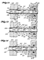
- Figs. 5-8 the prestressing operation of the invention is illustrated.
- Two abutting workpieces 130 and 132 adapted to be secured together by a fastener, have holes 134 and 136, respectively, drilled therethrough.
- the hole 136 has a countersink 138 which typically is made in the same operation as the hole 136, the countersink having the same angle as the surfaces 94 of the jaws 90.
- the mandrel 32 is in the fully extended position relative to the gun 30 and has been moved through the holes 134 and 136.
- the sleeve 126 is positioned on the small diameter portion 62 of mandrel 32.
- the outer end surface 35 of the nose cap 34 is spaced from the workpiece surface 140.
- the outer surface of the boss 58 is in contact with the surfaces 116 of the segments of the ring 102 so that the segments of both rings are tilted with respect to the gun and the workpiece.
- the surfaces 88 are in full contact with the shoulder 38 of the nose cap 34 and the conical surfaces 94 of the jaws are in partial contact with the countersink 138.
- the shoulder area 122 of the surfaces 114 of the ring 102 are in contact with the inner end of the sleeve and the cylindrical surface 80 of the ring 74 engage the inner end of the sleeve but are tilted away from the sleeve as they extend axially outwardly.
- the split sleeve 126 is installed on the mandrel 32 prior to inserting the mandrel 32 and sleeve 126 into the hole to be expanded and prestressed.
- a clearance between the sleeve and the wall of the hole is necessary and is equal to approximately 0.003 inch.
- the mandrel has been retracted substantially with respect to the work piece 130, and the increasing diameter portion 64 and the maximum diameter portion 66 have prestressed the area around the hole 134 as indicated by the broken lines 144 and 146, respectively.
- the diameter of the sleeve 126 is stretched and the prestressed area is compressed as shown.
- the surfaces 116 of the ring 102 had moved into abutment with the shoulder 50 on the inner cap.
- the surfaces 100 and 114 of the respective rings had moved into abutment so as to be at right angles to the axis of the mandrel.
- the cylindrical surfaces of the ring passage 80 had moved into contact with the sleeve and the conical surfaces 94 of the jaws 90 had moved so as to fully engage the countersink 138 but with no radial pressure.
- the shoulders 122 fully restrain the sleeve against any axial movement.
- the ring members remain axially in the same positions as in Fig. 6, and as the mandrel is retracted, the changing diameter portion 64 stretches the hole portions as it passes therethrough.
- mandrel 32 is in a position where the prestressing of the cylindrical hole portions has been completed.
- the sleeve is further stretched so as to move the ring segments 76 of the ring 74 radially outwardly, Fig. 7, so that the conical surfaces 94 of the jaws 90 move into a high pressure prestressing contact with the countersink surface 138.
- the very substantial compressive force exerted thereagainst prestresses the countersink region as shown in Figs. 7 and 8.
- the maximum diameter portion 66 has moved out of the hole portions and has stretched the entire sleeve so that the inner end is in contact with the cylindrical surfaces 80 of the ring 74.
- the maximum diameter portion 66 continues to exert radial force on the ring so as to continue the stretching of the countersink until it moves almost totally out of the inner end of the sleeve.
- the prestressing of the couuntersink has been completed to the extent shown in Fig. 2, where the prestressing on the countersink is the same distance from the surface thereof as is the distance of the prestressing from the wall surface of the hole, in contrast to the prior art prestressing shown in Fig. 1.
- a considerable pulling force is required to pull the mandrel through the sleeve and cold-expand or prestress the hole and countersink.
- the maximum diameter cylindrical portion 66 of the mandrel increases the friction and pulling forces during the prestressing operation around the hole. For 3/16" - 1/2" diameter holes in various aluminums these forces are in the range of 2,000 to 9,000 lbs. This same pulling force on the mandrel reacts against the jaws 90 and this reaction prevents the surfaces 94 from sliding out of the countersink during the prestressing operation.
- the jaws 94 are held axially in the countersink by means of the positioning of the two rings 74 and 102 between the shoulders 38 and 50 and the arrangement of the sleeve on the shoulders 122, but this arrangement does not cause any great prestressing force against the countersink.
- the coefficient of friction of the lubricant within the sleeve and the axial length of mandrel portion 66 are controlled in order to obtain an effective reaction force.
- the length of mandrel portion 66 is substantially equal to the diameter at mandrel portion 66.
- Another feature that helps maintain the jaw surfaces 94 on the countersink is that the outside of the sleeve is not lubricated. It first locks itself in the wall of the hole when the mandrel starts to expand the hole, and the friction between the outside of the sleeve and the jaws also provides a force to contain the segmented jaws in the countersink. As previously stated, the coefficient of friction of the lubricant within the sleeve is controlled as a further way of maintaining the jaw surfaces 94 on the countersink.
- Figs. 9 and 10 the workpiece 132 is shown after the hole and countersink have been prestressed. That is, when the sleeve and mandrel have been removed, the hole 136 has been expanded to be as 136A and the countersink has been expanded to be as 138A. As the split sleeve 126 is expanded in the hole, its diameter is stretched and the split is widened. The presence of the split results in formation of a small ridge 156. Similarly, the splits between the jaw surfaces 94 create very small marks 158 in the countersink. The marks in the countersink are of no significance to the rivets or bolts that fit into the fastener holes. In some installations it may be desirable to remove the ridge 156 by broaching or reaming, but it is now believed that resizing broaching is unnecessary.
- a threaded inner end portion 237 of the mandrel 232 screws into an internally threaded blind bore received in an extendable-retractable portion 239 of the puller gun 30.
- An O-ring seal 240 is preferably provided between flange 236 and the outer end portion of member 239. When assembled, the flange 236 is sandwiched between the outer end portion of member 239 and the inner radial surface of a flange provided at the outer end of member 243. The member 168 threads onto both the outer portion of member 243 and the threaded outer end portion of the barrel 245 of the puller 30.
- a generally cylindrical nose cap 160 (Figs. 11-13 and 19) is provided adjacent the working and outer end of the pull gun and is adapted to secure a small diameter, elongated generally tubular countersink prestressing member or device 162 within the outer end of the gun 10.
- the cap 160 has an outer radial end wall 164 formed to include a cylindrical center opening 166.
- Axially inwardly of the wall 18 is an external cylindrical wall 168 having internal threads 170 (Fig. 19) terminating axially forwardly in a small diameter portion 172 forming an inwardly extension of the opening 166.
- a flange 174 formed by the wall 164 and which is adapted to retain a radially extending cylindrical flange base 176 of the countersink prestressing device 162 (Figs. 11, 19 and 20).
- the flange 176 has an axially directed cylindrical wall 178 which at its inner end has counterbore 180 (Fig. 19). Extending outwardly of the counterbore and through the. device 162 is a generally central tubular passage 182.
- the countersink prestressing device is first formed as indicated by the structure shown as 162A in Figs. 14 and 15.
- the device 162A has the same flange configuration as the device 162 and extending outwardly from the flange 176 is a continuous cylindrical wall 184.
- the fingers 186A are spaced by a multiple number of axially directed slots 192A, having generally parallel sides.
- the outer ends of the fingers 186A are formed of radial annular surfaces 194A.
- the structure 162A as shown in Figs. 14 and 15 is made from an ultra high strength alloy steel, or equivalent, prior to heat-treating.
- the heat-treating process and the resulting structure in the form of the device 162 is discussed with respect to Figs. 16-18 in which the internal surfaces of the device are not shown, except for the passageway 182 at the outer end which is slightly smaller in diameter than the passage 182A at the outer end (Fig. 15).
- the remainder of the interior is substantially the same after heat-treating as shown in Figs. 19 and 20, with respect to which it will be described.
- the fingers 186A are clamped together (Fig. 16) with a ring 196 which narrows the slots 192A into axially directed slits 198 and 200.
- the surfaces of the slits 198 extend generally along the finger portions 188, and the surfaces 200 of the slits are substantially in contact inwardly of the radial surfaces 194, the contact extending substantially inwardly along the conical surfaces 190.
- the external surfaces of the fingers 186 also change from those of the fingers 186A in that the portions 188 are tapered outwardly from their inner ends to the conical surfaces 190.
- the outer surfaces of the finger portions 188 in cross section have decreasing diameters in the outwardly direction so that the device is generally conical outwardly of the uninterrupted cylindrical wall portion 184.
- the device as shown in Fig. 16, is heat-treated and quenched in a conventional manner and then the ring 196 is removed. After the removal of the ring, the device 162 retains the shape shown in Figs. 16-18.
- the heat-treating process substantially hardens the steel and stiffens the spring fingers 186 so that the conical prestressing surfaces 190 are able to exert great force on the countersink during the prestressing operation.
- the conical angle of the surfaces 190 is complementary to the angle of the countersink of the hole to be prestressed.
- the internal configuration of the finished device 16 is best seen in Figs. 19 and 20.
- the passageway therethrough is bordered by the internal surfaces of the fingers 186, outwardly of the uninterrupted cylindrical wall 184.
- Internal surfaces 202 of the finger portions 188 tend to form smaller diameters axially outwardly.
- Axially outwardly of the surfaces 202 are conical shoulders 204 with the diameters decreasing axially outwardly.
- the shoulders 204 provide cam follower surfaces.
- finger surfaces 206 which are only slightly conical having their diameters decreasing outwardly.
- the counterbore 180 is adapted to receive an annular spring in the form of an elastomeric O-ring 208.
- the outer end of the O-ring 208 abuts a shoulder 210 of the bore.
- An annular flange 212 of a sleeve retainer generally designated as 214 (Fig. 1) supports the 0-ring 208 inwardly within the gun 10.
- the sleeve retainer 214 is somewhat similar in configuration to the countersink device and is made of the same type of material, generally a heat-treated ultra high strength alloy steel.
- the sleeve retainer 214 has a generally cylindrical passageway 222 therethrough, adapted to extend over the mandrel 232 and to be slidably engaged within the passageway. of the countersink device 162.
- the sleeve retainer 214 has four annularly spaced, axially directed slots 224 extending inwardly from its outer end surfaces 226 on which there are annular cam surfaces 228 extending so as to be generally parallel, in side view, Fig. 20, to the cam follower surfaces 204 on the countersink device. Spaced between the slots 224 are four stiff axially directed spring fingers 230. The reduced diameter portions withstanding more than 400,000 psi. See the aforementioned U.S. Patent 3,566,662 and U.S. Patent No. 3,665,744 for detailed descriptions of the sleeves and a manner of constructing them.
- the preferred lubricant comprises a molydenum disulfide, graphite, a binder, a solvent (e.g.
- the coefficient of friction of this lubricant can be varied by changing the various components. As stated, the lubricant allows the mandrel to expand the countersink, the force required to expand the countersink being higher than that required to expand the straight portion of the hole.
- the inner small diameter slightly conical portions 206 of the fingers 186 of the countersink device are biased inwardly so as to tend to be in relatively tight contact with the mandrel portion 234 to prevent the insertion of the sleeve 240 on the mandrel 232 to the end of the retainer in its position of retention for the prestressing operation.
- the mandrel 232 is moved outwardly so that the abutting member 236 makes contact with the inner surface of the inner cylindrical portion 216 of the retainer and continues outwardly until the abutting member makes contact with the inwardly directed flange on the retaining nut 238. In this movement the inner flange 212 is moved outwardly to compress the O-ring spring 208.
- the cam edges 228 on the outer end of the retainer 214 make contact with the cam followers 204 axially inwardly of the small diameter portions 206 on each of the fingers 186 so as to move the outer ends of the fingers radially outwardly away from the cylindrical portion 234 of the mandrel 232.
- a slight retraction of the mandrel 232 so that its abutting member 236 is moved away from the inner end of the retainer portion 216 permits the 0-ring 208 to be expanded so as to move the flange 212 inwardly into its normal position against the locking nut 238 (Fig. 20).
- Figs. 21-24 the prestressing operation of the invention is illustrated.
- the mandrel 232 has been started in the retraction direction, indicated by the arrow on the cylindrical portion 234, and the increasing diameter portion 252 has started prestressing of the material around the hole 248.
- the conical surfaces 190 of the countersink prestressing device become tightly engaged in the countersink surface 250 of the hole 246.
- the retainer 214 becomes tightly engaged with the end of the sleeve 240 to hold it in place during the prestressing operation.
- the internal diameter surfaces 206 at the end of the fingers 186 also tightly engage the sleeve 240 to keep it in contact with the retainer 214 and the mandrel surfaces as they pass therethrough.
- the mandrel 232 has been retracted substantially with respect to the workpiece 244 and the increasing diameter portion 252 and the maximum diameter portion 254 prestress the area around the hole 248, as indicated by the change in configuration or cold-expansion of the sleeve portion in the hole 248. That is, the metal around the hole 248 is in compression and as the increasing diameter portion 252 moves into the hole 246, expansion of the sleeve and hole 246 has commenced.
- the prestressing of the hole 134 and of the countersink 250 has been substantially completed.
- the generally cylindrical surfaces 188 on the ends of the fingers 186 remain in contact with the sleeve 240 and aid in holding the sleeve 240 on the end of the retainer 214 so that the sleeve 240 is held within the workpiece.
- the extent of the countersink prestressing is illustrated in Fig. 2.
- a considerable pulling force is required to pull the mandrel 232 through the sleeve 240 and cold-expand or prestress the holes 246, 248 and countersink 250.
- the maximum diameter cylindrical portion 254 of the mandrel 232 greatly increases the friction and pulling forces around the hole during the prestressing operation. By way of example, for 3/16 inch - 1/2 inch diameter holes in various aluminums, these forces are in the range of 2,000 to 9,000 pounds.
- This same pulling force on the mandrel 232 reacts against the conical surfaces 190 of the fingers 186 and this reaction prevents the surfaces 190 from moving out of the countersink 250 during the prestressing operation.
- the fingers 186 are of great strength and are held axially in the countersink by the mandrel 232 exerting pressure on the conical surfaces 190 against the countersink 250.
- Another feature that helps maintain the conical surfaces 190 in the countersink 250 is that the outside of the sleeve 240 is not lubricated. It first locks itself in the walls of the holes 246, 248 when the mandrel 232 starts to expand the hole, and the friction between the outside of the sleeve 240 and the surfaces 206 also provides a force to contain the split finger ends having the conical surfaces 46 in the countersink 250.
- the relatively small diameter of the countersink prestressing device 162 and the arrangement of small diameter retainer 214 substantially concentrically engaged therein, outwardly of the gun provides great advantages in the prestressing of countersunk fastener holes.
- the small outside diameter of the prestressing device 162 is particularly adapted for use in prestressing through a drill bushing in a drill fixture.
- Such drill fixtures are typically positioned and temporarily fixed in front of the workpiece in which holes are to be drilled and then prestressed by cold expansion. In the drilling operation, the fixtures are used to guide drills through the drill bushings so as to position all of the holes in the correction location.
- the small diameter prestressing device allows the manufacturer to leave the drill fixture in position after drilling, for the cold expansion portion of the operation, and thus enables the final reaming operation to be made through the drill bushing holes which remain in register with the original holes as drilled. It should be appreciated that the diameter of the prestressing device is only slightly greater than the diameter of the countersink being prestressed.
- the outer end of the gun is positioned a substantial distance from the workpiece so that the gun would not interfere with protuberances on the workpiece and the small diameter of the device 162 would prevent contact with the protuberances extending from the workpiece. If necessary, the device 162 could be made substantially longer than as shown to avoid protuberances.
Landscapes
- Engineering & Computer Science (AREA)
- Mechanical Engineering (AREA)
- Drilling And Boring (AREA)
- Dowels (AREA)
- Finish Polishing, Edge Sharpening, And Grinding By Specific Grinding Devices (AREA)
Priority Applications (1)
| Application Number | Priority Date | Filing Date | Title |
|---|---|---|---|
| AT83100398T ATE42054T1 (de) | 1982-02-10 | 1983-01-18 | Verfahren und vorrichtung zum vorspannen eines versenkten befestigungsloches. |
Applications Claiming Priority (2)
| Application Number | Priority Date | Filing Date | Title |
|---|---|---|---|
| US06/347,739 US4425780A (en) | 1982-02-10 | 1982-02-10 | Apparatus having extended prestressing and sleeve retaining devices for prestressing countersunk fastener holes and method |
| US347739 | 1982-02-10 |
Publications (3)
| Publication Number | Publication Date |
|---|---|
| EP0086344A2 true EP0086344A2 (de) | 1983-08-24 |
| EP0086344A3 EP0086344A3 (en) | 1986-04-16 |
| EP0086344B1 EP0086344B1 (de) | 1989-04-12 |
Family
ID=23365052
Family Applications (1)
| Application Number | Title | Priority Date | Filing Date |
|---|---|---|---|
| EP83100398A Expired EP0086344B1 (de) | 1982-02-10 | 1983-01-18 | Verfahren und Vorrichtung zum Vorspannen eines versenkten Befestigungsloches |
Country Status (6)
| Country | Link |
|---|---|
| US (1) | US4425780A (de) |
| EP (1) | EP0086344B1 (de) |
| JP (1) | JPS58192638A (de) |
| AT (1) | ATE42054T1 (de) |
| DE (1) | DE3379577D1 (de) |
| IL (1) | IL67810A0 (de) |
Cited By (1)
| Publication number | Priority date | Publication date | Assignee | Title |
|---|---|---|---|---|
| EP1961503A1 (de) * | 2007-02-23 | 2008-08-27 | Neturen Co., Ltd. | Dorn, Satz von Dornen und hohle Zahnstange |
Families Citing this family (38)
| Publication number | Priority date | Publication date | Assignee | Title |
|---|---|---|---|---|
| GB2221180A (en) * | 1988-07-29 | 1990-01-31 | Avdel Systems Ltd | Fastener installation apparatus |
| US5038596A (en) * | 1989-12-01 | 1991-08-13 | Grumman Aerospace Corporation | Threaded cold working mandrel |
| US5083363A (en) * | 1990-07-25 | 1992-01-28 | Fatigue Technology, Inc. | Method of installing a grommet in a wall of composite material |
| US5096349A (en) * | 1990-07-26 | 1992-03-17 | Fatigue Technology, Inc. | Nut mounting grommet |
| US5245743A (en) * | 1990-07-26 | 1993-09-21 | Fatigue Technology, Inc. | Method of installing a nut mounting grommet |
| US5103548A (en) * | 1991-05-13 | 1992-04-14 | Fatigue Technology, Inc. | Method and apparatus for securing a tubular bushing in a circular opening |
| US5127254A (en) * | 1991-07-10 | 1992-07-07 | Fatigue Technology, Inc. | Method and apparatus for split sleeve cold expansion of openings in structural members |
| US5305627A (en) * | 1992-07-27 | 1994-04-26 | Fatigue Technology, Inc. | Split sleeve cold expansion |
| US5380136A (en) * | 1993-09-14 | 1995-01-10 | Fatigue Technology, Inc. | Anchor nut mount |
| US5433100A (en) * | 1993-11-12 | 1995-07-18 | Fatigue Technology, Inc. | Apparatus for split sleeve and tubular bushing cold expansion |
| US7375277B1 (en) * | 2000-06-26 | 2008-05-20 | Fatigue Technology, Inc. | Double flanged bushings and installation methods |
| US7114900B2 (en) * | 2001-11-09 | 2006-10-03 | Textron Inc. | Push-type rivetless nut plate and method and apparatus for installing same |
| US7059816B2 (en) | 2001-11-09 | 2006-06-13 | Textron Inc. | Nut plate |
| US7448652B2 (en) * | 2003-07-31 | 2008-11-11 | Fatigue Technology Inc. | Tubular metal fitting expandable in a wall opening and method of installation |
| US20070053761A1 (en) * | 2004-08-03 | 2007-03-08 | Scott Cohen | Sealed rivetless nut plate |
| US20060090318A1 (en) * | 2004-11-04 | 2006-05-04 | Toosky Rahmatollah F | Self-aligning tool for installation of pull type fastener |
| US20070110541A1 (en) * | 2005-10-28 | 2007-05-17 | Fatigue Technology, Inc. | Radially displaceable bushing for retaining a member relative to a structural workpiece |
| EP3199292B1 (de) | 2005-12-28 | 2020-03-11 | Fatigue Technology, Inc. | Dorneinheit und verfahren zu ihrer verwendung |
| AU2007204888B2 (en) * | 2006-01-11 | 2012-08-16 | Fatigue Technology, Inc. | Bushing kits, bearings, and methods of installation |
| US20070227215A1 (en) * | 2006-02-27 | 2007-10-04 | Surface Technology Holdings, Ltd. | Method and apparatus for preventing or arresting crack development and propagation |
| WO2007127399A2 (en) | 2006-04-27 | 2007-11-08 | Fatigue Technology, Inc. | Wave relieving geometric features in structural members that are radially expandable into workpieces |
| JP5258751B2 (ja) * | 2006-04-27 | 2013-08-07 | ファティーグ テクノロジー インコーポレイテッド | アラインメント装置およびその使用方法 |
| US20080005887A1 (en) * | 2006-05-26 | 2008-01-10 | Fatigue Technology, Inc. | Elongated member/radially expandable member assembly and methods of assembling the same |
| US7958766B2 (en) * | 2006-06-29 | 2011-06-14 | Fatigue Technology, Inc. | Self-aligning tools and a mandrel with retention sleeve |
| KR101468399B1 (ko) | 2006-08-28 | 2014-12-03 | 퍼티구 테크놀로지 인코포레이티드 | 설치/처리 시스템 및 이를 사용하는 방법 |
| US7575404B2 (en) * | 2006-11-01 | 2009-08-18 | Sps Technologies, Llc | Nut plate fastener assembly for composite materials |
| EP2158409A2 (de) * | 2007-05-15 | 2010-03-03 | Fatigue Technology, Inc. | Installierter, spreizbarer rollladenbund und mit einem gewinde versehenes innenglied |
| EP2210001B1 (de) | 2007-10-16 | 2017-08-02 | Fatigue Technology, Inc. | Dehnbare befestigungsvorrichtungsanordnung mit deformiertem bund |
| US10010983B2 (en) * | 2008-03-07 | 2018-07-03 | Fatigue Technology, Inc. | Expandable member with wave inhibitor and methods of using the same |
| EP2318726B1 (de) * | 2008-07-18 | 2015-09-02 | Fatigue Technology, Inc. | Annietmutteranordnung und verwendungsverfahren dafür |
| EP2417369B1 (de) | 2009-04-10 | 2014-04-02 | Fatigue Technology, Inc. | Verbinderanordnung für eine aufweitbare hülse und ein befestiger mit einem ziehdorn |
| EP2513499B1 (de) | 2009-12-16 | 2015-04-08 | Fatigue Technology, Inc. | Modularer mutternhalter und verfahren zu seiner anwendung |
| WO2012167136A2 (en) | 2011-06-03 | 2012-12-06 | Fatigue Technology, Inc. | Expandable crack inhibitors and methods of using the same |
| US9114449B2 (en) | 2011-06-15 | 2015-08-25 | Fatigue Technology, Inc. | Modular nut plates with closed nut assemblies |
| US11033311B2 (en) | 2012-01-12 | 2021-06-15 | University Of Kansas | Compact orthopedic anti-rotation device |
| US10130985B2 (en) | 2012-01-30 | 2018-11-20 | Fatigue Technology, Inc. | Smart installation/processing systems, components, and methods of operating the same |
| CN104226833B (zh) * | 2013-06-09 | 2016-03-30 | 宝山钢铁股份有限公司 | 一种钢管全长扩径时的在线整圆方法及扩径模具 |
| CN105964816B (zh) * | 2016-05-28 | 2018-10-23 | 浙江尔格科技股份有限公司 | 一种胀管器 |
Family Cites Families (16)
| Publication number | Priority date | Publication date | Assignee | Title |
|---|---|---|---|---|
| US1647447A (en) | 1922-12-28 | 1927-11-01 | Babcock & Wilcox Co | Method of fastening tubular bodies in holes of other bodies |
| US2459808A (en) | 1945-10-11 | 1949-01-25 | George A Geyer | Tube expander with expansible ball drift removable by its expansion |
| US3056197A (en) | 1960-02-17 | 1962-10-02 | Scovill Manufacturing Co | Method of making coupling ferrules |
| US3157305A (en) | 1961-10-05 | 1964-11-17 | Huck Mfg Co | Nose assembly |
| US3270410A (en) | 1963-05-20 | 1966-09-06 | Briles Mfg | Method of prestressed fastening of materials |
| US3693247A (en) | 1968-10-03 | 1972-09-26 | Clarence K Brown | Method of securing together a plurality of structural members |
| US3566662A (en) | 1969-04-28 | 1971-03-02 | Boeing Co | Coldworking method and apparatus |
| US3596491A (en) | 1969-05-19 | 1971-08-03 | Battelle Development Corp | Method for tapering tubes |
| US3835688A (en) | 1970-04-30 | 1974-09-17 | J King | Apparatus and method for sizing holes |
| US3665744A (en) | 1970-05-21 | 1972-05-30 | Clair M Harter | Method and apparatus for making sleeves |
| US3805578A (en) | 1973-01-17 | 1974-04-23 | J King | Apparatus and method for enlarging holes |
| US3943748A (en) | 1973-01-17 | 1976-03-16 | King John O Jun | Coldwork system with delay split sleeve |
| US3949535A (en) | 1973-01-17 | 1976-04-13 | King John O Jun | Coldworked joint held by seamless tubular member |
| US3892121A (en) | 1973-09-12 | 1975-07-01 | Boeing Co | Apparatus for cold-working holes |
| US4187708A (en) | 1977-04-11 | 1980-02-12 | Industrial Wire & Metal Forming, Inc. | Pulling apparatus and method |
| US4127345A (en) | 1977-09-21 | 1978-11-28 | Huck Manufacturing Company | Lock spindle blind fastener for single action application |
-
1982
- 1982-02-10 US US06/347,739 patent/US4425780A/en not_active Expired - Lifetime
-
1983
- 1983-01-18 EP EP83100398A patent/EP0086344B1/de not_active Expired
- 1983-01-18 AT AT83100398T patent/ATE42054T1/de not_active IP Right Cessation
- 1983-01-18 DE DE8383100398T patent/DE3379577D1/de not_active Expired
- 1983-02-01 IL IL67810A patent/IL67810A0/xx not_active IP Right Cessation
- 1983-02-10 JP JP58021386A patent/JPS58192638A/ja active Granted
Cited By (3)
| Publication number | Priority date | Publication date | Assignee | Title |
|---|---|---|---|---|
| EP1961503A1 (de) * | 2007-02-23 | 2008-08-27 | Neturen Co., Ltd. | Dorn, Satz von Dornen und hohle Zahnstange |
| US8365573B2 (en) | 2007-02-23 | 2013-02-05 | Neutron Co., Ltd. | Mandrel, set of mandrels, and hollow rack bar |
| US9046157B2 (en) | 2007-02-23 | 2015-06-02 | Neturen Co., Ltd. | Mandrel, set of mandrels, and hollow rack bar |
Also Published As
| Publication number | Publication date |
|---|---|
| EP0086344A3 (en) | 1986-04-16 |
| JPH0479791B2 (de) | 1992-12-16 |
| US4425780A (en) | 1984-01-17 |
| DE3379577D1 (en) | 1989-05-18 |
| EP0086344B1 (de) | 1989-04-12 |
| IL67810A0 (en) | 1983-06-15 |
| ATE42054T1 (de) | 1989-04-15 |
| JPS58192638A (ja) | 1983-11-10 |
Similar Documents
| Publication | Publication Date | Title |
|---|---|---|
| EP0086344B1 (de) | Verfahren und Vorrichtung zum Vorspannen eines versenkten Befestigungsloches | |
| US4423619A (en) | Apparatus and method for prestressing a countersunk fastener hole | |
| US4557033A (en) | Method of cold expanding and sizing fastener holes | |
| US4471643A (en) | Method and apparatus for prestressing fastener holes | |
| US4524600A (en) | Apparatus for prestressing fastener holes | |
| US5433100A (en) | Apparatus for split sleeve and tubular bushing cold expansion | |
| US5103548A (en) | Method and apparatus for securing a tubular bushing in a circular opening | |
| US5245743A (en) | Method of installing a nut mounting grommet | |
| EP2061626B1 (de) | Vorrichtung zum Bearbeiten eines strukturellen Werkstücks und Verfahren zum Ausdehnen eines ausdehnbaren Elements | |
| EP0468598B1 (de) | Mittels Mutter befestigte Durchführung und Verfahren zu deren Einbau | |
| US5341559A (en) | Method and apparatus for securing a tubular bushing in a circular opening | |
| EP1166951B1 (de) | Montageverfahren für Buschen mit Doppelflansch | |
| US2146461A (en) | Method of riveting | |
| US4934170A (en) | Fatigue life enhancement of noncircular openings | |
| US6993816B2 (en) | Retaining ring installation tool | |
| US4142439A (en) | Blind fastener assembly | |
| US3835688A (en) | Apparatus and method for sizing holes | |
| US4597282A (en) | Method and apparatus for coldworking holes | |
| EP0581385A1 (de) | Kaltexpansion für geschlitzte Buchse | |
| US7448652B2 (en) | Tubular metal fitting expandable in a wall opening and method of installation | |
| EP0725221B1 (de) | Verfahren zum Befestigen von Bauteilen einer Zusammenstellung | |
| GB1604504A (en) | Blind fastener | |
| GB2094928A (en) | Plug assembly and method of plugging a passage | |
| GB2140891A (en) | Swaged-in threaded fastener | |
| WO2024179924A1 (en) | A sealing plug assembly, a method of manufacturing the same, and a method of sealing a hole in a workpiece with a sealing plug assembly |
Legal Events
| Date | Code | Title | Description |
|---|---|---|---|
| PUAI | Public reference made under article 153(3) epc to a published international application that has entered the european phase |
Free format text: ORIGINAL CODE: 0009012 |
|
| PUAI | Public reference made under article 153(3) epc to a published international application that has entered the european phase |
Free format text: ORIGINAL CODE: 0009012 |
|
| AK | Designated contracting states |
Designated state(s): AT BE CH DE FR GB IT LI LU NL SE |
|
| PUAL | Search report despatched |
Free format text: ORIGINAL CODE: 0009013 |
|
| AK | Designated contracting states |
Kind code of ref document: A3 Designated state(s): AT BE CH DE FR GB IT LI LU NL SE |
|
| 17P | Request for examination filed |
Effective date: 19860425 |
|
| 17Q | First examination report despatched |
Effective date: 19870701 |
|
| ITF | It: translation for a ep patent filed | ||
| GRAA | (expected) grant |
Free format text: ORIGINAL CODE: 0009210 |
|
| AK | Designated contracting states |
Kind code of ref document: B1 Designated state(s): AT BE CH DE FR GB IT LI LU NL SE |
|
| PG25 | Lapsed in a contracting state [announced via postgrant information from national office to epo] |
Ref country code: SE Effective date: 19890412 Ref country code: AT Effective date: 19890412 |
|
| REF | Corresponds to: |
Ref document number: 42054 Country of ref document: AT Date of ref document: 19890415 Kind code of ref document: T |
|
| REF | Corresponds to: |
Ref document number: 3379577 Country of ref document: DE Date of ref document: 19890518 |
|
| ET | Fr: translation filed | ||
| PG25 | Lapsed in a contracting state [announced via postgrant information from national office to epo] |
Ref country code: LU Free format text: LAPSE BECAUSE OF NON-PAYMENT OF DUE FEES Effective date: 19900131 |
|
| PLBE | No opposition filed within time limit |
Free format text: ORIGINAL CODE: 0009261 |
|
| STAA | Information on the status of an ep patent application or granted ep patent |
Free format text: STATUS: NO OPPOSITION FILED WITHIN TIME LIMIT |
|
| 26N | No opposition filed | ||
| ITTA | It: last paid annual fee | ||
| PGFP | Annual fee paid to national office [announced via postgrant information from national office to epo] |
Ref country code: BE Payment date: 19940121 Year of fee payment: 12 |
|
| PGFP | Annual fee paid to national office [announced via postgrant information from national office to epo] |
Ref country code: FR Payment date: 19940126 Year of fee payment: 12 |
|
| PGFP | Annual fee paid to national office [announced via postgrant information from national office to epo] |
Ref country code: DE Payment date: 19940128 Year of fee payment: 12 |
|
| PGFP | Annual fee paid to national office [announced via postgrant information from national office to epo] |
Ref country code: NL Payment date: 19940131 Year of fee payment: 12 |
|
| PGFP | Annual fee paid to national office [announced via postgrant information from national office to epo] |
Ref country code: CH Payment date: 19940307 Year of fee payment: 12 |
|
| PG25 | Lapsed in a contracting state [announced via postgrant information from national office to epo] |
Ref country code: LI Effective date: 19950131 Ref country code: CH Effective date: 19950131 Ref country code: BE Effective date: 19950131 |
|
| BERE | Be: lapsed |
Owner name: FAITGUE TECHNOLOGY INC. Effective date: 19950131 |
|
| PG25 | Lapsed in a contracting state [announced via postgrant information from national office to epo] |
Ref country code: NL Effective date: 19950801 |
|
| PG25 | Lapsed in a contracting state [announced via postgrant information from national office to epo] |
Ref country code: FR Effective date: 19950929 |
|
| REG | Reference to a national code |
Ref country code: CH Ref legal event code: PL |
|
| NLV4 | Nl: lapsed or anulled due to non-payment of the annual fee |
Effective date: 19950801 |
|
| PG25 | Lapsed in a contracting state [announced via postgrant information from national office to epo] |
Ref country code: DE Effective date: 19951003 |
|
| REG | Reference to a national code |
Ref country code: FR Ref legal event code: ST |
|
| PGFP | Annual fee paid to national office [announced via postgrant information from national office to epo] |
Ref country code: GB Payment date: 20011231 Year of fee payment: 20 |
|
| REG | Reference to a national code |
Ref country code: GB Ref legal event code: IF02 |
|
| PG25 | Lapsed in a contracting state [announced via postgrant information from national office to epo] |
Ref country code: GB Free format text: LAPSE BECAUSE OF EXPIRATION OF PROTECTION Effective date: 20030117 |
|
| REG | Reference to a national code |
Ref country code: GB Ref legal event code: PE20 Effective date: 20030117 |