EP0086347B2 - Klappe für Lüftungskanäle - Google Patents
Klappe für Lüftungskanäle Download PDFInfo
- Publication number
- EP0086347B2 EP0086347B2 EP83100457A EP83100457A EP0086347B2 EP 0086347 B2 EP0086347 B2 EP 0086347B2 EP 83100457 A EP83100457 A EP 83100457A EP 83100457 A EP83100457 A EP 83100457A EP 0086347 B2 EP0086347 B2 EP 0086347B2
- Authority
- EP
- European Patent Office
- Prior art keywords
- flap
- foam
- edge
- longitudinal
- edges
- Prior art date
- Legal status (The legal status is an assumption and is not a legal conclusion. Google has not performed a legal analysis and makes no representation as to the accuracy of the status listed.)
- Expired - Lifetime
Links
Images

Classifications
-
- B—PERFORMING OPERATIONS; TRANSPORTING
- B32—LAYERED PRODUCTS
- B32B—LAYERED PRODUCTS, i.e. PRODUCTS BUILT-UP OF STRATA OF FLAT OR NON-FLAT, e.g. CELLULAR OR HONEYCOMB, FORM
- B32B5/00—Layered products characterised by the non- homogeneity or physical structure, i.e. comprising a fibrous, filamentary, particulate or foam layer; Layered products characterised by having a layer differing constitutionally or physically in different parts
- B32B5/18—Layered products characterised by the non- homogeneity or physical structure, i.e. comprising a fibrous, filamentary, particulate or foam layer; Layered products characterised by having a layer differing constitutionally or physically in different parts characterised by features of a layer of foamed material
-
- B—PERFORMING OPERATIONS; TRANSPORTING
- B32—LAYERED PRODUCTS
- B32B—LAYERED PRODUCTS, i.e. PRODUCTS BUILT-UP OF STRATA OF FLAT OR NON-FLAT, e.g. CELLULAR OR HONEYCOMB, FORM
- B32B27/00—Layered products comprising a layer of synthetic resin
- B32B27/06—Layered products comprising a layer of synthetic resin as the main or only constituent of a layer, which is next to another layer of the same or of a different material
- B32B27/065—Layered products comprising a layer of synthetic resin as the main or only constituent of a layer, which is next to another layer of the same or of a different material of foam
-
- B—PERFORMING OPERATIONS; TRANSPORTING
- B60—VEHICLES IN GENERAL
- B60H—ARRANGEMENTS OF HEATING, COOLING, VENTILATING OR OTHER AIR-TREATING DEVICES SPECIALLY ADAPTED FOR PASSENGER OR GOODS SPACES OF VEHICLES
- B60H1/00—Heating, cooling or ventilating devices
- B60H1/00642—Control systems or circuits; Control members or indication devices for heating, cooling or ventilating devices
- B60H1/00664—Construction or arrangement of damper doors
- B60H1/00671—Damper doors moved by rotation; Grilles
- B60H1/00678—Damper doors moved by rotation; Grilles the axis of rotation being in the door plane, e.g. butterfly doors
-
- F—MECHANICAL ENGINEERING; LIGHTING; HEATING; WEAPONS; BLASTING
- F16—ENGINEERING ELEMENTS AND UNITS; GENERAL MEASURES FOR PRODUCING AND MAINTAINING EFFECTIVE FUNCTIONING OF MACHINES OR INSTALLATIONS; THERMAL INSULATION IN GENERAL
- F16K—VALVES; TAPS; COCKS; ACTUATING-FLOATS; DEVICES FOR VENTING OR AERATING
- F16K15/00—Check valves
- F16K15/02—Check valves with guided rigid valve members
- F16K15/03—Check valves with guided rigid valve members with a hinged closure member or with a pivoted closure member
-
- F—MECHANICAL ENGINEERING; LIGHTING; HEATING; WEAPONS; BLASTING
- F24—HEATING; RANGES; VENTILATING
- F24F—AIR-CONDITIONING; AIR-HUMIDIFICATION; VENTILATION; USE OF AIR CURRENTS FOR SCREENING
- F24F13/00—Details common to, or for air-conditioning, air-humidification, ventilation or use of air currents for screening
- F24F13/24—Means for preventing or suppressing noise
-
- B—PERFORMING OPERATIONS; TRANSPORTING
- B60—VEHICLES IN GENERAL
- B60H—ARRANGEMENTS OF HEATING, COOLING, VENTILATING OR OTHER AIR-TREATING DEVICES SPECIALLY ADAPTED FOR PASSENGER OR GOODS SPACES OF VEHICLES
- B60H1/00—Heating, cooling or ventilating devices
- B60H1/00642—Control systems or circuits; Control members or indication devices for heating, cooling or ventilating devices
- B60H1/00664—Construction or arrangement of damper doors
- B60H2001/007—Manufacturing or assembling
-
- Y—GENERAL TAGGING OF NEW TECHNOLOGICAL DEVELOPMENTS; GENERAL TAGGING OF CROSS-SECTIONAL TECHNOLOGIES SPANNING OVER SEVERAL SECTIONS OF THE IPC; TECHNICAL SUBJECTS COVERED BY FORMER USPC CROSS-REFERENCE ART COLLECTIONS [XRACs] AND DIGESTS
- Y10—TECHNICAL SUBJECTS COVERED BY FORMER USPC
- Y10T—TECHNICAL SUBJECTS COVERED BY FORMER US CLASSIFICATION
- Y10T137/00—Fluid handling
- Y10T137/6851—With casing, support, protector or static constructional installations
- Y10T137/7036—Jacketed
-
- Y—GENERAL TAGGING OF NEW TECHNOLOGICAL DEVELOPMENTS; GENERAL TAGGING OF CROSS-SECTIONAL TECHNOLOGIES SPANNING OVER SEVERAL SECTIONS OF THE IPC; TECHNICAL SUBJECTS COVERED BY FORMER USPC CROSS-REFERENCE ART COLLECTIONS [XRACs] AND DIGESTS
- Y10—TECHNICAL SUBJECTS COVERED BY FORMER USPC
- Y10T—TECHNICAL SUBJECTS COVERED BY FORMER US CLASSIFICATION
- Y10T137/00—Fluid handling
- Y10T137/7722—Line condition change responsive valves
- Y10T137/7837—Direct response valves [i.e., check valve type]
- Y10T137/7898—Pivoted valves
-
- Y—GENERAL TAGGING OF NEW TECHNOLOGICAL DEVELOPMENTS; GENERAL TAGGING OF CROSS-SECTIONAL TECHNOLOGIES SPANNING OVER SEVERAL SECTIONS OF THE IPC; TECHNICAL SUBJECTS COVERED BY FORMER USPC CROSS-REFERENCE ART COLLECTIONS [XRACs] AND DIGESTS
- Y10—TECHNICAL SUBJECTS COVERED BY FORMER USPC
- Y10T—TECHNICAL SUBJECTS COVERED BY FORMER US CLASSIFICATION
- Y10T428/00—Stock material or miscellaneous articles
- Y10T428/24—Structurally defined web or sheet [e.g., overall dimension, etc.]
- Y10T428/24273—Structurally defined web or sheet [e.g., overall dimension, etc.] including aperture
- Y10T428/24322—Composite web or sheet
- Y10T428/24331—Composite web or sheet including nonapertured component
- Y10T428/24339—Keyed
- Y10T428/24347—From both sides
Definitions
- the invention relates to a flap for ventilation ducts, in particular for motor vehicle air conditioning systems.
- an openly used flap which has a flap body with a pocket-shaped foam casing, two foam layers folded longitudinally around a flap being glued to the broad sides of the flap body. The protruding edges of the foam layers are glued together.
- the foam layer has an adhesive layer.
- the invention is based on the object of improving a flap for ventilation ducts of the type mentioned at the outset with sufficient noise-damping properties, in particular in terms of production technology.
- This object is achieved according to the invention by providing a flap body provided with holes and a pocket-shaped foam covering for the flap body, two foam layers folded around one of the longitudinal flap edges being covered on their surfaces facing the perforated broad flap sides with an adhesive-activated film which covers the foam zones projecting beyond the flap edges and the like connects to each other in the area of the opposing foam sections.
- the flap can have an articulation axis running in the region of one of the longitudinal edges of the flap body and parallel to this longitudinal edge, the longitudinal edge of the flap body opposite the longitudinal edge being designed as a flap contact edge.
- This further development is characterized in that the folded edge of the foam layers is arranged on the flap contact edge. This creates an uninterrupted pocket formation on the actual flap closing body.
- a ventilation duct flap with a high sound insulation value which is favorable in terms of production is created. Both the flowing wind and vibrations no longer occur as an annoying source of noise.
- the sheet as diecut he g tellbare in a simple way valve is placed between the pocket-like folded foam layers and held under pressure sensitive activation of the film. It is not even necessary to deburr the die-cut, since the foam used provides adequate protective or cushioning coverage of the mostly sharp edges.
- the flap is assigned to the bearing means without risk of injury.
- the foam zones projecting beyond the flap edges are connected to one another via the film.
- the foam it can even be assumed that the material is open-pored, since the activatable film itself acts as a closing skin. It can be assigned to the foam layer blank in a continuous process.
- the foam casing which is firmly connected to the flap die-cut, is held so that it cannot move due to its fixation in the area of the protruding foam zones and the additional connection in the area of the holes provided in the die-cut.
- the foam zone folded around the flap's longitudinal edge is particularly stable since there is no interruption in the foam structure; Rather, it maintains its homogeneous structure, even though the pore structure is also somewhat densified there.
- the holes also reduce the weight of the flap.
- the flap body 1 which in the exemplary embodiment is flat and has a substantially long rectangular shape, forms, in the region of its two upper corners, cut-out projections 2 for attaching bearing means (not shown). These are assigned pin projections or bearing recesses in the air duct brackets.
- the valve joint axis is marked with xx.
- the valve body consists of a stamped sheet metal with a wall thickness of approx. 1 mm.
- the entire middle length of the flap is pierced by a total of holes 3.
- Last tere are circular and extend at equal distances from each other. Instead of the three relatively large holes, it can be an even richer perforated plate or even a sieve-like perforated plate.
- the flap body 1 is embedded in a pocket-shaped foam casing U.
- the latter consists of two foam layers I and II folded around the lower longitudinal flap edge 1 '. These have the same floor plan shape.
- the cut is somewhat larger than that of the valve body 1 itself, so that an all-round projection y remains over the edge R of the valve body 1, namely about four times the valve thickness.
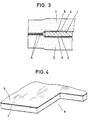
- the foam layers I, II are covered on their surfaces 4 facing the flap broad sides with an adhesive-activated film 5.
- the latter is anchored to the foam structure. It can be a thermoplastic film, so that the foam zones projecting beyond the flap edges R and the foam sections opposite each other in the area of the holes 3 connect to one another.
- the foam casing U is then fixed. Even certain lifts in the central region of the valve body 1 that can be assumed from the restoring force of the material are excluded due to the thorough anchoring in the region of the holes 3. A flat image is created. With small foam material thicknesses, there is at most a slight indentation in the area of the holes, as is shown in FIGS. 2 and 3. The corresponding trough does not appear in the case of thicker layers. The visually practically insignificant depression can also be tolerated, since the flap bodies are attached to the air ducts out of sight.
- the pocket-shaped casing U is cut back.
- the corresponding niches are labeled 6.
- bearing parts can be plugged on, which thus receive direct contact with the free-standing flap section there.
- the flap contact edge 7 opposite the hinge axis x-x is rounded according to the corresponding folding of the pocket-forming foam cut.
- the rounding generally corresponds to the layer thickness, but can flatten out slightly due to a certain amount of folding.
- This zone is seamless, i. H. the foam structure remains homogeneous there.
- the film has a small wall thickness. It practically only forms a cuticle.
Landscapes
- Engineering & Computer Science (AREA)
- Mechanical Engineering (AREA)
- General Engineering & Computer Science (AREA)
- Physics & Mathematics (AREA)
- Thermal Sciences (AREA)
- Chemical & Material Sciences (AREA)
- Combustion & Propulsion (AREA)
- Duct Arrangements (AREA)
- Air-Flow Control Members (AREA)
- Helmets And Other Head Coverings (AREA)
- Packages (AREA)
Description
- Die Erfindung betrifft eine Klappe für Lüftungskanäle, insbesondere für Kraftfahrzeug-Klimaanlagen.
- Aus der US-A-4 276 954 ist eine Klappe der in Rade stehenden Art bekannt, bei der ein inneres Traggerüst aus einem extrudierten Aluminiumprofil ein isolierendes Schaumstoffmaterial formschlüssig einfaßt. Das Aluminiumprofil bildet dabei die gegenüberliegenden Längskanten der Klappe. Durch die Fixierung des isolierenden Schaumstoffmaterials mittels eines komplizierten Aluminiumprofils ist die Herstellung der bekannten Klappe aufwendig. Außerdem ist das isolierende Material nicht längs des Klappenumfanges geschlossen, sondern durch metallische Bereiche unterbrochen, was die wärme- und schallisolierende Eigenschaft beeinträchtigt. Femer ist die Klappe aufgrund der beschriebenen Konstruktion vergleichsweise schwer.
- Weiter ist eine offenkundig vorbenutzte Klappe bekannt, die einen Klappenkörper mit einer taschenförmigen Schaumstoffummantelung aufweist, wobei zwei um eine Klappen längskannte gefaltete Schaumstofflagen mit den Breitseiten des Klappenkörpers verklebt sind. Die überstehenden Ränder der Schaumstofflagen sind gegeneinander verklebt. Die Schaumstofflage weisen eine Kleberschicht auf.
- Der Erfindung liegt demgegenüber die Aufgabe zugrunde, eine Klappe für Lüftungskanäle der eingangs erwähnten Art mit ausreichender geräuschdämmemder Eigenschaft im insbesondere herstellungstechnischer Hinsicht zu verbessern.
- Diese Aufgabe wird erfindungsgemäß gelöst durch Vorsehen eines mit Löchern versehenen Klappenkörpers und einer taschenförmigen Schaumstoffummamtelung fürden Klappenkörper, wobei zwei um eine der Klappenlängskanten gefaltete Schaumstofflagen an ihren den durchlöcherten Klappenbreitseiten zugekehrten Flächen mit einer haftaktivierten Folie bedeckt sind, welche die über die Klappenränder vorstehenden Schaumstoffzonen und die sich im Bereich der Löcher gegenüberliegenden Schaumstoffabschnitte untereinander verbindet.
- Die Klappe kann gemäß einer Weiterbildung der Erfindung eine im Bereich einer der Längskanten des Klappenkörpers und parallel zu dieser Längskante verlaufende Gelenkachse haben, wobei die der Längskante gegenübediegende Längskante des Klappenkörpers als Klappenanlagekante ausgebildet ist. Diese Weiterbildung zeichnet sich dadurch aus, daß die Faltkante der Schaumstofflagen an der Klappenanlagekante angeordnet ist. Dadurch wird eine unterbrechungsfreie Taschenbildung am eigentlichen Klappenschließkörper erreicht.
- Zufolge der erfindungsgemäßen Ausgestaltung ist eine fertigungsgünstige Lüftungskanal-Klappe mit hohem Schalldämmwert geschaffen. Sowohl der durchströmende Wind als auch Vibrationen treten nicht mehr als lästige Geräuschquelle auf. Die in einfacher Weise als Blechstanzling ergtellbare Klappe wird zwischen die taschenartig gefalteten Schaumstofflagen gelegt und unter Haftaktivierung der Folie festgehalten. Dabei ist es nicht einmal erforderlich, den Stanzling zu entgraten, da der verwendete Schaumstoff eine hinreichende schützende bzw. polsternde Abdeckung der meist scharfen Randkanten ergibt.
- Das Zuordnen der Klappe in die Lagermittel geschieht ohne Verletzungsgefahr. Die überdie Klappenränder vorstehenden Schaumstoffzonen sind über die Folie miteinander verbunden. Bezüglich des Schaumstoffes kann sogar von offenporigem Material ausgegangen werden, da die aktivierbare Folie selbst als verschließende Haut wirkt. Sie läßt sich dem Schaumstofflagen-Zuschnitt im Durchlaufverfahren zuordnen. Die mit dem Klappen-Stanzling fest verbundene Schaumstoffummantelung ist durch ihre Fixierung im Bereich der vorstehenden Schaumstoffzonen und durch die zusätzliche Verbindung im Bereich der im Stanzling vorgesehenen Löcher verschiebefest gehalten. Dabei ist die um die eine Klappenlängskante gefaltete Schaumstoffzone besonders kantenstabil, da hier keine Unterbrechung der Schaumstoffstruktur vorliegt; diese behält vielmehr ihre homogene Struktur bei, wenngleich sich auch das Porengefüge dort etwas verdichtet Die Löcher verringern überdies das Eigengewicht der Klappe. Außerdem ist es nicht mehr erforderlich, der Klappe einen elastischen Dichtungskörper im Klappenrahmen zuzuordnen. Ein solcher Dichtungskörper ist vielmehr direkt an der Klappe selbst durch die Schaumstoffummantelung geschaffen.
- Weitere Vorteile und Einzelheiten der Erfindung sind nachstehend anhand eines zeichnerisch veranschaulichten Ausführungsbeispiels näher erläutert. Es zeigen :
- Fig. 1 die erfindungsgemäß ausgebildete Klappe im Ansicht,
- Fig. 2 dem Schnitt gemäß Linie 11-11 im Fig. 1,
- Fig. 3 dem Schnitt gemäß Linie 111-111 im Fig. 1, und zwar in gegenüber Fig. 1 vergrößertem Maßstab und
- Fig. 4 einen perspektivischen Ausschnitt eines Eckbereichs der Schaumstofflage mit haftaktivierbarer Folie.
- Der beim Ausführungsbeispiel ebenflächige, im wesentlichen lang rechteckig gestaltete Klappenkörper 1 bildet im Bereich seiner beiden oberen Ecken freigeschnittene Vorsprünge 2 aus zum Ansetzen von nicht näher dargestellten Lagermitteln. Diesen sind Zapfenvorsprünge oder Lägervertiefungen in Halterungen des Luftkanales zugeordnet. Die Klappengelenkachse ist mit x-x bezeichnet. Der Klappenkörper besteht aus einem Blechstanzling von ca. 1 mm Wandungsdicke. Der Klappenmittelbereich ist auf ganzer Länge durch insgesamt Löcher 3 durchbrochen. Letztere sind kreisrund und erstrecken sich in gleichen Abständen zueinander. Statt der drei relativ groBen Löcher kann es sich um eine noch reicher gelochte Platte handeln bzw. sogar um eine siebartige Lochplatte.
- Der Klappenkörper 1 ist in einer taschenförmigen Schaumstoffummantelung U eingebettet. Letztere besteht aus zwei um die untere Klappenlängskante 1' gefaltete Schaumstofflagen I und Il. Diese besitzen flächengleiche Grundrißform. Der Zuschnitt ist etwas größer als der des Klappenkörpers 1 selbst, so daß ein allseitiger Überstand y über den Rand R des Klappenkörpers 1 verbleibt, und zwar von etwa der vierfachen Klappendicke.
- Die Schaumstofflagen I, ll sind an ihren den Klappenbreitseiten zugekehrten Flächen 4 mit einer haftaktivierten Folie 5 bedeckt. Letztere ist an der Schaumstoffstruktur verankert. Es kann sich um eine thermoplastische Folie handeln, so daß sich die über die Klappenränder R vorstehenden Schaumstoffzonen und die sich im Bereich der Löcher 3 gegenüberliegenden Schaumstoffabschnitte untereinander verbinden. Die Schaumstoffummantelung U liegt hiernach fest. Selbst gewisse aus der Rückstellkraft des Materiales anzunehmende Abhebungen im Mittelbereich des Klappenkörpers 1 sind augeschlossen zufolge der durchgreifenden Verankerung im Bereich der Löcher 3. Es entsteht ein ebenflächiges Bild. Bei geringen Schaumstoffmaterialdicken tritt allenfalls eine leichte Einziehung im Bereich der Löcher auf, wie dies in den Fig. 2 und 3 dargestellt ist. Bei größeren Lagendicken zeichnet sich die entsprechende Mulde nicht ab. Die optisch praktisch unbedeutende Einsenkung kann auch hingenommen werden, da die Klappenkörper der Sicht entzogen im Bereich der Luftkanäle angebracht sind.
- Im lagerbildenden Eckbereich ist die taschenförmige Ummantelung U zurückgeschnitten. Die entsprechenden Nischen sind mit 6 bezeichnet. Hier können bspw. Lagerteile aufgesteckt werden, die so eine unmittelbare Anlage am dortigen, freistehenden Klappenabschnitt erhalten.
- Die der Gelenkachse x-x gegenüberliegende Klappenanlagekante 7 ist quergerundet zufolge der entsprechenden Umfaltung des taschenbildenden Schaumstoffzuschnitts. Die Rundung entspricht im allgemeinen der Lagendicke, kann sich jedoch aufgrund eines gewissen Falt-Zugs leicht abflachen. Diese Zone ist nahtfrei, d. h. die Schaumstoffstruktur bleibt dort homogen.
- Die Folie ist von geringer Wandungsdicke. Sie bildet praktisch nur ein Häutchen.
Claims (2)
Priority Applications (1)
| Application Number | Priority Date | Filing Date | Title |
|---|---|---|---|
| AT83100457T ATE14046T1 (de) | 1982-01-28 | 1983-01-20 | Klappe fuer lueftungskanaele. |
Applications Claiming Priority (2)
| Application Number | Priority Date | Filing Date | Title |
|---|---|---|---|
| DE8202047U DE8202047U1 (de) | 1982-01-28 | 1982-01-28 | Klappe für Lüftungskanäle |
| DE8202047U | 1982-01-28 |
Publications (3)
| Publication Number | Publication Date |
|---|---|
| EP0086347A1 EP0086347A1 (de) | 1983-08-24 |
| EP0086347B1 EP0086347B1 (de) | 1985-06-26 |
| EP0086347B2 true EP0086347B2 (de) | 1991-08-07 |
Family
ID=6736411
Family Applications (1)
| Application Number | Title | Priority Date | Filing Date |
|---|---|---|---|
| EP83100457A Expired - Lifetime EP0086347B2 (de) | 1982-01-28 | 1983-01-20 | Klappe für Lüftungskanäle |
Country Status (5)
| Country | Link |
|---|---|
| US (1) | US4506699A (de) |
| EP (1) | EP0086347B2 (de) |
| AT (1) | ATE14046T1 (de) |
| DE (2) | DE8202047U1 (de) |
| ES (1) | ES270046Y (de) |
Families Citing this family (14)
| Publication number | Priority date | Publication date | Assignee | Title |
|---|---|---|---|---|
| FR2630530B1 (fr) * | 1988-04-22 | 1992-07-17 | Renault | Conduit de ventilation notamment pour la climatisation de vehicules automobiles |
| DE3836541C2 (de) * | 1988-10-27 | 1997-05-15 | Illbruck Industrieprodukte Gmb | Verfahren zur Herstellung einer Klappe für Lüftungskanäle |
| FR2654809B1 (fr) * | 1989-11-17 | 1992-02-07 | Ferco Int Usine Ferrures | Boitier d'entree d'air isophonique a aeration autoregulee. |
| USD349754S (en) | 1991-11-14 | 1994-08-16 | Pawar Gurdeep S | Insulated cover for a backflow prevention water valve |
| DE4204189A1 (de) * | 1992-02-13 | 1993-08-19 | Schako Metallwarenfabrik | Umlenkschalldaempfer |
| FR2704184B1 (fr) * | 1993-04-23 | 1995-06-23 | Valeo Thermique Habitacle | Volet pour appareil de chauffage ou de climatisation. |
| FR2709343B1 (fr) * | 1993-08-25 | 1995-10-27 | Abb Flakt | Bouche d'aération auto-réglable, acoustiquement isolante. |
| DE4425029A1 (de) * | 1994-07-15 | 1996-01-18 | Behr Gmbh & Co | Luftklappe für eine Heizungs- oder eine Klimaanlage |
| DE19513670B4 (de) * | 1995-04-11 | 2006-03-16 | Behr Gmbh & Co. Kg | Klappe für einen Luftführungskanal |
| DE19961949C1 (de) * | 1999-12-22 | 2001-03-22 | Emil Siegwart | Absperrklappe für eine Luftleitung und Verfahren zu ihrer Herstellung |
| JP4345240B2 (ja) * | 2000-08-25 | 2009-10-14 | 株式会社デンソー | 空調用ドアの組付構造 |
| EP1344668B1 (de) * | 2002-03-15 | 2006-11-08 | TRW Automotive Electronics & Components GmbH & Co. KG | Belüftungsdüse für Lüftungssysteme |
| JP6251480B2 (ja) * | 2013-02-12 | 2017-12-20 | 川崎重工業株式会社 | 車両用空調ダクト及び鉄道車両 |
| CN107074063B (zh) * | 2014-12-02 | 2019-07-26 | 翰昂汽车零部件有限公司 | 车用左/右独立的空调装置 |
Family Cites Families (11)
| Publication number | Priority date | Publication date | Assignee | Title |
|---|---|---|---|---|
| DE7320111U (de) * | 1973-09-27 | Piffko H | Thermisch isolierende Platten und Profile | |
| US2632722A (en) * | 1948-02-27 | 1953-03-24 | Tenak Products Company | Moldable tablet |
| US3813896A (en) * | 1973-01-26 | 1974-06-04 | Vollrath Co | Freezer air vent |
| US4067764A (en) * | 1977-03-15 | 1978-01-10 | Sierracin Corporation | Method of manufacture of solar cell panel |
| DE2734229A1 (de) * | 1977-07-29 | 1979-02-01 | Klein Schanzlin & Becker Ag | Weichdichtende rueckschlagklappe |
| US4294283A (en) * | 1977-11-25 | 1981-10-13 | Scharres Harry J | Wedge sealed damper |
| US4191205A (en) * | 1978-03-21 | 1980-03-04 | Nash Franklin A | Thermoplastic check valve |
| DE2815756C3 (de) * | 1978-04-12 | 1982-01-28 | Ernst-Wilhelm 5303 Bornheim Müller | Prothetisches Verschlußelement zum Ersatz der Klappen im menschlichen Herzen |
| DE2830717A1 (de) * | 1978-07-13 | 1980-01-31 | Gewerk Keramchemie | Bauplatte aus thermoplastischem, schweissbarem kunststoff |
| DE2856833A1 (de) * | 1978-12-30 | 1980-07-17 | Hoechst Ag | Identifikationskarte und verfahren zu ihrer herstellung |
| US4276954A (en) * | 1979-10-01 | 1981-07-07 | Acoustic Standards | Adjustable light and air-admitting window thermal and acoustic barrier system |
-
1982
- 1982-01-28 DE DE8202047U patent/DE8202047U1/de not_active Expired
-
1983
- 1983-01-17 US US06/458,395 patent/US4506699A/en not_active Expired - Fee Related
- 1983-01-20 DE DE8383100457T patent/DE3360308D1/de not_active Expired
- 1983-01-20 EP EP83100457A patent/EP0086347B2/de not_active Expired - Lifetime
- 1983-01-20 AT AT83100457T patent/ATE14046T1/de not_active IP Right Cessation
- 1983-01-27 ES ES1983270046U patent/ES270046Y/es not_active Expired
Also Published As
| Publication number | Publication date |
|---|---|
| EP0086347B1 (de) | 1985-06-26 |
| DE3360308D1 (en) | 1985-08-01 |
| ES270046Y (es) | 1984-02-01 |
| ATE14046T1 (de) | 1985-07-15 |
| EP0086347A1 (de) | 1983-08-24 |
| ES270046U (es) | 1983-07-16 |
| US4506699A (en) | 1985-03-26 |
| DE8202047U1 (de) | 1982-06-24 |
Similar Documents
| Publication | Publication Date | Title |
|---|---|---|
| EP0086347B2 (de) | Klappe für Lüftungskanäle | |
| DE69820155T2 (de) | Dachhimmel für Kraftfahrzeuge | |
| DE69806939T2 (de) | Dichtungsstreifen | |
| DE4019121C2 (de) | Halterung für eine Motorhaubenschallisolierung | |
| EP0846069B1 (de) | Profile für plattenförmige verbundelemente | |
| EP1023194A1 (de) | Scheibeneinheit | |
| DE1801148A1 (de) | Abdeck- und Zierleistenbefestigung bei eingeklebten Scheiben,insbesondere fuer Kraftfahrzeuge | |
| DE3834054C3 (de) | Hitzeschild | |
| DE10357998A1 (de) | Schnapprahmen-Sonnenblende | |
| EP0146101B1 (de) | Dichtungsprofil | |
| DE2929689A1 (de) | Karosseriefeste dachanordnung fuer ein kraftfahrzeug | |
| DE2646663C3 (de) | Faltenbalg für Gelenkfahrzeuge | |
| DE10354572B4 (de) | Dichtungsprofil für ein schwenkbares Karosserieteil | |
| DE102008020148A1 (de) | Flexibles Dichtungsprofil, insbesondere für Portale von Nutzfahrzeugen | |
| DE3733230A1 (de) | Scheibensystem, insbesondere fuer autotueren | |
| DE3629865C2 (de) | ||
| DE19632184C2 (de) | Federbein mit elastischer Auflage zwischen Schraubenfeder und Federteller | |
| DE102005013005B4 (de) | Dichtung, insbesondere zum Abdichten der Karosserie eines Kraftfahrzeugs | |
| DE10237022C5 (de) | Filtereinsatz | |
| DE2035807A1 (de) | Bauelement zur Schall- und Wärmeisolierung | |
| EP1512350B1 (de) | Aus Schaumstoff oder Latex bestehender Innenkern einer Polsterung | |
| EP0233552A1 (de) | Elastische Dichtung | |
| DE3018213A1 (de) | Zierleiste fuer kraftfahrzeugfenster | |
| WO2005042333A1 (de) | Dichtelement zur anordnung zwischen einer kfz-lenksäulen-abdeckung und einem verkleidungsteil, anordnung aus einem dichtelement und einem verkleidungsteil sowie verfahren zur montage des dichtelements an einem verkleidungsteil | |
| DE4234760A1 (de) | Sonnenschutzblende |
Legal Events
| Date | Code | Title | Description |
|---|---|---|---|
| PUAI | Public reference made under article 153(3) epc to a published international application that has entered the european phase |
Free format text: ORIGINAL CODE: 0009012 |
|
| PUAI | Public reference made under article 153(3) epc to a published international application that has entered the european phase |
Free format text: ORIGINAL CODE: 0009012 |
|
| AK | Designated contracting states |
Designated state(s): AT BE CH DE FR GB IT LI LU NL SE |
|
| 17P | Request for examination filed |
Effective date: 19830714 |
|
| ITF | It: translation for a ep patent filed | ||
| GRAA | (expected) grant |
Free format text: ORIGINAL CODE: 0009210 |
|
| AK | Designated contracting states |
Designated state(s): AT BE CH DE FR GB IT LI LU NL SE |
|
| REF | Corresponds to: |
Ref document number: 14046 Country of ref document: AT Date of ref document: 19850715 Kind code of ref document: T |
|
| REF | Corresponds to: |
Ref document number: 3360308 Country of ref document: DE Date of ref document: 19850801 |
|
| ET | Fr: translation filed | ||
| PLBI | Opposition filed |
Free format text: ORIGINAL CODE: 0009260 |
|
| 26 | Opposition filed |
Opponent name: SUEDDEUTSCHE KUEHLERFABRIK JULIUS FR. BEHR GMBH & Effective date: 19860308 |
|
| NLR1 | Nl: opposition has been filed with the epo |
Opponent name: SUEDDEUTSCHE KUEHLERFABRIK JULIUS FR.BEHR GMBH & C |
|
| REG | Reference to a national code |
Ref country code: FR Ref legal event code: CA |
|
| PLAB | Opposition data, opponent's data or that of the opponent's representative modified |
Free format text: ORIGINAL CODE: 0009299OPPO |
|
| R26 | Opposition filed (corrected) |
Opponent name: BEHR GMBH & CO. Effective date: 19860308 |
|
| NLXE | Nl: other communications concerning ep-patents (part 3 heading xe) |
Free format text: IN PAT.BUL.10/86,CORR.:BEHR GMBH & CO. |
|
| PUAH | Patent maintained in amended form |
Free format text: ORIGINAL CODE: 0009272 |
|
| STAA | Information on the status of an ep patent application or granted ep patent |
Free format text: STATUS: PATENT MAINTAINED AS AMENDED |
|
| ITF | It: translation for a ep patent filed | ||
| 27A | Patent maintained in amended form |
Effective date: 19910807 |
|
| AK | Designated contracting states |
Kind code of ref document: B2 Designated state(s): AT BE CH DE FR GB IT LI LU NL SE |
|
| ET3 | Fr: translation filed ** decision concerning opposition | ||
| REG | Reference to a national code |
Ref country code: CH Ref legal event code: AEN |
|
| NLR2 | Nl: decision of opposition | ||
| NLR3 | Nl: receipt of modified translations in the netherlands language after an opposition procedure | ||
| ITTA | It: last paid annual fee | ||
| EPTA | Lu: last paid annual fee | ||
| EAL | Se: european patent in force in sweden |
Ref document number: 83100457.7 |
|
| APAC | Appeal dossier modified |
Free format text: ORIGINAL CODE: EPIDOS NOAPO |
|
| APAC | Appeal dossier modified |
Free format text: ORIGINAL CODE: EPIDOS NOAPO |
|
| PGFP | Annual fee paid to national office [announced via postgrant information from national office to epo] |
Ref country code: SE Payment date: 19970115 Year of fee payment: 15 Ref country code: LU Payment date: 19970115 Year of fee payment: 15 |
|
| PGFP | Annual fee paid to national office [announced via postgrant information from national office to epo] |
Ref country code: CH Payment date: 19970120 Year of fee payment: 15 |
|
| PG25 | Lapsed in a contracting state [announced via postgrant information from national office to epo] |
Ref country code: LU Free format text: LAPSE BECAUSE OF NON-PAYMENT OF DUE FEES Effective date: 19980120 |
|
| PG25 | Lapsed in a contracting state [announced via postgrant information from national office to epo] |
Ref country code: SE Free format text: LAPSE BECAUSE OF NON-PAYMENT OF DUE FEES Effective date: 19980121 |
|
| PG25 | Lapsed in a contracting state [announced via postgrant information from national office to epo] |
Ref country code: LI Free format text: LAPSE BECAUSE OF NON-PAYMENT OF DUE FEES Effective date: 19980131 Ref country code: CH Free format text: LAPSE BECAUSE OF NON-PAYMENT OF DUE FEES Effective date: 19980131 |
|
| REG | Reference to a national code |
Ref country code: CH Ref legal event code: PL |
|
| EUG | Se: european patent has lapsed |
Ref document number: 83100457.7 |
|
| PGFP | Annual fee paid to national office [announced via postgrant information from national office to epo] |
Ref country code: DE Payment date: 20011228 Year of fee payment: 20 |
|
| REG | Reference to a national code |
Ref country code: GB Ref legal event code: IF02 |
|
| PGFP | Annual fee paid to national office [announced via postgrant information from national office to epo] |
Ref country code: FR Payment date: 20020114 Year of fee payment: 20 |
|
| PGFP | Annual fee paid to national office [announced via postgrant information from national office to epo] |
Ref country code: NL Payment date: 20020116 Year of fee payment: 20 Ref country code: BE Payment date: 20020116 Year of fee payment: 20 Ref country code: AT Payment date: 20020116 Year of fee payment: 20 |
|
| PGFP | Annual fee paid to national office [announced via postgrant information from national office to epo] |
Ref country code: GB Payment date: 20020121 Year of fee payment: 20 |
|
| PG25 | Lapsed in a contracting state [announced via postgrant information from national office to epo] |
Ref country code: GB Free format text: LAPSE BECAUSE OF EXPIRATION OF PROTECTION Effective date: 20030119 |
|
| PG25 | Lapsed in a contracting state [announced via postgrant information from national office to epo] |
Ref country code: NL Free format text: LAPSE BECAUSE OF EXPIRATION OF PROTECTION Effective date: 20030120 Ref country code: AT Free format text: LAPSE BECAUSE OF EXPIRATION OF PROTECTION Effective date: 20030120 |
|
| BE20 | Be: patent expired |
Owner name: *IRBIT HOLDING A.G. Effective date: 20030120 |
|
| REG | Reference to a national code |
Ref country code: GB Ref legal event code: PE20 Effective date: 20030119 |
|
| NLV7 | Nl: ceased due to reaching the maximum lifetime of a patent |
Effective date: 20030120 |
|
| APAH | Appeal reference modified |
Free format text: ORIGINAL CODE: EPIDOSCREFNO |