EP0086385A1 - Verfahren und Vorrichtung zum Formgebung - Google Patents
Verfahren und Vorrichtung zum Formgebung Download PDFInfo
- Publication number
- EP0086385A1 EP0086385A1 EP83100867A EP83100867A EP0086385A1 EP 0086385 A1 EP0086385 A1 EP 0086385A1 EP 83100867 A EP83100867 A EP 83100867A EP 83100867 A EP83100867 A EP 83100867A EP 0086385 A1 EP0086385 A1 EP 0086385A1
- Authority
- EP
- European Patent Office
- Prior art keywords
- station
- mold sections
- mold
- sections
- molding
- Prior art date
- Legal status (The legal status is an assumption and is not a legal conclusion. Google has not performed a legal analysis and makes no representation as to the accuracy of the status listed.)
- Granted
Links
- 238000000034 method Methods 0.000 title claims abstract description 36
- 238000000465 moulding Methods 0.000 title claims abstract description 35
- 239000004033 plastic Substances 0.000 claims abstract description 5
- 238000000071 blow moulding Methods 0.000 claims description 9
- 229920001169 thermoplastic Polymers 0.000 claims description 5
- 239000004416 thermosoftening plastic Substances 0.000 claims description 5
- 230000001939 inductive effect Effects 0.000 claims description 2
- 239000012815 thermoplastic material Substances 0.000 claims 1
- 230000007246 mechanism Effects 0.000 abstract description 15
- 238000001125 extrusion Methods 0.000 description 6
- 230000008901 benefit Effects 0.000 description 4
- 238000007664 blowing Methods 0.000 description 4
- 239000000969 carrier Substances 0.000 description 3
- 238000001816 cooling Methods 0.000 description 2
- 239000000463 material Substances 0.000 description 2
- 238000005452 bending Methods 0.000 description 1
- 230000000694 effects Effects 0.000 description 1
- 238000010101 extrusion blow moulding Methods 0.000 description 1
- 238000001746 injection moulding Methods 0.000 description 1
- 238000004519 manufacturing process Methods 0.000 description 1
- 238000007789 sealing Methods 0.000 description 1
- 239000007787 solid Substances 0.000 description 1
- 125000006850 spacer group Chemical group 0.000 description 1
Images

Classifications
-
- B—PERFORMING OPERATIONS; TRANSPORTING
- B29—WORKING OF PLASTICS; WORKING OF SUBSTANCES IN A PLASTIC STATE IN GENERAL
- B29C—SHAPING OR JOINING OF PLASTICS; SHAPING OF MATERIAL IN A PLASTIC STATE, NOT OTHERWISE PROVIDED FOR; AFTER-TREATMENT OF THE SHAPED PRODUCTS, e.g. REPAIRING
- B29C49/00—Blow-moulding, i.e. blowing a preform or parison to a desired shape within a mould; Apparatus therefor
- B29C49/28—Blow-moulding apparatus
- B29C49/30—Blow-moulding apparatus having movable moulds or mould parts
- B29C49/32—Blow-moulding apparatus having movable moulds or mould parts moving "to and fro"
-
- B—PERFORMING OPERATIONS; TRANSPORTING
- B29—WORKING OF PLASTICS; WORKING OF SUBSTANCES IN A PLASTIC STATE IN GENERAL
- B29C—SHAPING OR JOINING OF PLASTICS; SHAPING OF MATERIAL IN A PLASTIC STATE, NOT OTHERWISE PROVIDED FOR; AFTER-TREATMENT OF THE SHAPED PRODUCTS, e.g. REPAIRING
- B29C33/00—Moulds or cores; Details thereof or accessories therefor
- B29C33/20—Opening, closing or clamping
- B29C33/22—Opening, closing or clamping by rectilinear movement
-
- B—PERFORMING OPERATIONS; TRANSPORTING
- B29—WORKING OF PLASTICS; WORKING OF SUBSTANCES IN A PLASTIC STATE IN GENERAL
- B29C—SHAPING OR JOINING OF PLASTICS; SHAPING OF MATERIAL IN A PLASTIC STATE, NOT OTHERWISE PROVIDED FOR; AFTER-TREATMENT OF THE SHAPED PRODUCTS, e.g. REPAIRING
- B29C49/00—Blow-moulding, i.e. blowing a preform or parison to a desired shape within a mould; Apparatus therefor
- B29C49/42—Component parts, details or accessories; Auxiliary operations
- B29C49/56—Opening, closing or clamping means
Definitions
- This invention relates generally to a method and apparatus for transferring blanks, plastic parisons, or other moldable articles. More particularly, the invention relates to a method and apparatus for transferring a plastic parison from an extrusion station to a blow molding station, using either the blow molds, preform molds, or both, to transfer the parison, without transferring the mechanism for applying the clamping forces to the molds.
- thermoplastic articles There exist various methods for forming blown thermoplastic articles. In general, one of these methods includes injection molding a parison and then blowing the parison into the completed article. In other methods, an extruded parison is blown into the shape of the final article, either with or without an intermediate blowing step to form a preform, for purposes well known in the art.
- blow molds are permanently fastened within the clamps, such that the heavy clamps travel with the molds.
- the molds and the heavy hydraulic mechanism for exerting force travel from station to station as the parison is transferred to different processing stations.
- the apparatus includes mold sections which are closeable along a first axis to form a mold cavity and which are also movable along a second axis from a first station where the mold sections may receive a moldable blank to a second station where the blank may be molded under pressure.
- a stationary clamp that does not move between the first and second stations presses the mold sections together at the second station for molding the blank under pressure.
- the blank may be an extruded parison to be blow molded in the second station.
- Optional biasing means may be provided to hold the mold sections sufficiently close together to hold the blank as the mold sections move from the first station to the second station.
- the molds may be closed under a low pressure at the first station and then that pressure is maintained as the molds are moved to the second station, whereupon a greater pressure is applied for the molding operation.
- the molds may be only partially closed, such that a slight spacing on the order of one-sixteenth inch to one inch is left between the mold sections, until the final closing forces are applied.
- the apparatus includes at least first and second molding stations which are spaced generally along a first axis.
- a pair of generally parallel clamping plates extend from the first to the second molding stations, but are spaced to be on opposite sides of those stations.
- Each plate includes a guide surface, upon which is mounted a mold section such that the molding sections can move between the first and second molding stations.
- Means are provided for moving the molding sections between the first and second molding stations; and additional means are provided for displacing the clamping plates toward and away from each other, so that the clamping plates can selectively open, close or clamp the molding sections.
- the apparatus further includes four spaced tie rods on which the clamping plates are mounted in order to distribute the clamping forces.
- a method for transferring articles to be molded in a sealed cavity including the steps of: transporting mold sections generally along a first axis to a first station; moving the mold sections generally along a second axis while at the first station to close the molds around a blank sufficiently to encapsulate the blank in an interior cavity formed by the mold sections; transporting the blank in the mold cavity to a second station by moving the closed mold sections along said first axis; and exerting a force on the mold sections at the second station to form a proper seal for molding, the force being exerted from a source which is stationary in relation to the first and second stations.
- the first and second forces may emanate from the same stationary source.
- Another preferred method of operation includes the steps of: transporting a pair of opened blow mold sections to a first station; at least partially closing the blow mold sections around a parison at the first station under a first force, which force is sufficient to hold the parison within the mold sections; transporting the at least partially closed mold sections with the enclosed parison to a second station while maintaining a force sufficient to transport the parison; and exerting a second force on the blow mold sections at the second station, the second force being substantially greater than the first, such that a proper seal is maintained for a molding operation.
- a single means may effect the closing of the molds and the application of the molding force on the molds which single means is stationary in relation to the first and second stations.
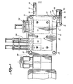
- the preferred embodiment is generally represented by a clamp assembly 20, a mold assembly 40, a link mechanism 60, biasing mechanism 70, and a transfer mechanism 80.
- a fixed vertical bar 12 mounted on a base 14.
- Two vertical tie rod supports 11 and 15 are also mounted on the base 14 as is a motor 16.
- the vertical tie rod supports 11 and 15 provide support for tie rod or bar 24 which is telescopically mated through the upper portion of the vertical tie rod supports.
- the tie rod or bar 24 is attached at one end to the lower portion of clamping member 21 and at the other end to the lower portion of a movable bar 29.
- Another tie rod 23 is attached at one end to the upper portion of clamping member or clamping plate 21 and at the other end to the upper portion of movable bar 29.
- Both tie rods 23 and 24 are integrally mated to clamping member 21 and movable bar 29 such that the two tie rods, the movable bar 29 and the clamping member 21 move as a unit. Thus, a force exerted against movable bar 29 will cause movement in the clamping member 21.
- Clamping member or clamping plate 22 is telescopically mated on the tie rods 23 and 24, such that it is free to move to or away from clamping member 21 in response to the movement of auxiliary link 66 and link mechanism 60.
- the clamping members 21 and 22 are provided with a lower recess 26 and an upper recess 25. These recesses are adapted to receive L-shaped extensions 45 and 46 of movable support plates 41 and 42, respectively.
- the movable support plates 41 and 42 are mounted to move along the face of their respective clamping members.
- the L-shaped extensions 45 and 46 are preferably of a smaller diameter than the lower and upper recesses 26 and 25 in order to allow self-adjustment of the movable support plates as the clamping members 21 and 22 are brought together to create a seal, as more fully described later.
- Blow mold halves or sections 43 and 44 are integrally mounted on movable support plates 41 and 42, respectivley, through means of spacers 41a and 42a.
- each blow mold half or section can slide on an axis parallel to the face of its respective clamping member, yet is mounted so as to respond to the movement of the clamping members to or away from each other and to receive forces exerted by the clamping members.
- link system 60 serves to assure that the clamping plates 21 and 22, and therefore molds 43 and 44, move an equal amount under the force exerted by hydraulic cylinder 200.
- the clamping members 21 and 22 are linked to a link mechanism 60 illustrated by the articulated lever system shown in Figure 1.
- a main link 67 is pivotally mounted on the fixed bar 12 such that it may pivot on the axis of fixed bar pin 65.
- the main link 67 is pivotally attached by pin 62 to an auxiliary link 66 on one end and by pin 63 to auxiliary link 68 on the other end.
- auxiliary link 66 is in turn pivotally attached to clamping member 22 by means of pin 61, while auxiliary link 68 is pivotally attached to movable bar 29 by means of pin 64.
- rotation of main link 67 about fixed bar pin 65 causes auxiliary links 66 and 68 to rotate about pins 62 and 63 respectively so as to force clamping member 22 to move further away or closer to fixed bar 12 depending on the direction of rotation of main link 67 as caused by the back and forth movement of movable bar 29.
- clockwise rotation of main link 67 about fixed bar pin 65 results in clamping member 22 and movable bar 29 moving toward each other, while counter clockwise rotation of main link 67 will result in clamping member 22 and movable bar 29 moving away from each other.
- the force applying mechanism may alternately be applied to clamping member 22 or movable bar 29. However, in most cases the force applying mechanism is preferably applied to both moveable bar 29 and clamping member 22.
- a transfer mechanism indicated generally at 80 is used to move the mold sections along the clamping members as the mold sections move from one station to the next.
- Shaft 86 is attached at one end to motor 16 and at the other end is rotatably mounted through clamping member 21.
- swing arm 85 is integrally mounted at one end to shaft 86 and at the other end to link arm 82 by means of link arm pin 83.
- rotation of shaft 86 by motor 16 causes swing arm 85 to rotate about the axis of shaft 86.
- link arm 82 is connected at its other end to frame 84 by means of link arm pin 81 rotation of shaft 86 causes the lateral movement of frame 84.
- clamping plates 21 and 22 are closed on each other under a low pressure to close the mold sections around a parison. Then the molds are transferred with the enclosed parison under the application of the low pressure to a second molding station. Alternatively, the molds may be moved sufficiently close, such as on the order of one-sixteenth inch to an inch, to simply hold the parison in place as the molds are moved between molding stations.
- clamping members 21 and 22 may be provided with optional biasing means shown generally at 70.
- a cup shaped plunger 77 is integrally attached by means of a shaft 74 to a plug 76.
- a spring 75 biases the plunger 77 away from clamping member 21 and up against the inside portion of movable support plate 41.
- Plug 76 may be adjusted so as to retract or extend plunger 77.
- a plurality of biasing means 70 may be provided for each clamping member.
- the adjustment of the various plugs 76 causes cup shaped plungers 77 to press against movable support plates 41 and 42 with varying degrees of force.
- the force exerted against movable support plates 41 and 42 may be varied as they travel along the face of clamping members 21 and 22, respectively.
- clamping member 21 is provided with additional tie bars 27 and 28, which serve the same function as their counterparts, bars 23 and 24.
- Tie rods 28 and 27 are mounted in a similar fashion as tie rods 23 and 24. Thus, they are telescopically mated with the upper and lower portions of clamping member 22 and are mounted at the end furthest away from clamp 21 to movable bar 29.
- An additional linking mechanism such as the articulated lever system shown generally at 60 may also be used.
- a rectangular shaped frame could be provided, the vertical portions of which would be integrally mounted to tie rods 23, 24, 27 and 28.
- Two articulated lever systems could be installed, both of which would be attached to the vertical sides of the frame in the manner shown in Figure 1.
- a hydraulic cylinder could be attached to the frame, such that movement of the frame closer to or further away from fixed bar 12 would increase or decrease the distance between clamping member 21 and clamping member 22.
- the articulated lever system could be mounted such that auxiliary link arm 68 would be attached to the center of the frame, while the tie rods 23, 24, 27 and 28 could be mounted at the four corners of the frame.
- the articulated lever system is mainly used to assure cooperation between the movement of movable bar 29 or an appropriate frame (not shown) and clamping member 22 the use of only one articullated lever system may be appropriate.
- the movable support plate may be provided with a transport arm 91 as shown in Figure 2.
- the transport arm 91 may be provided with carriers 92 and 93 which are adapted to support items being transferred from the blow mold halves or sections.
- the transport arm provides greater flexibility in integrating the system of the present invention with other processes. For example, these carriers on the transport arm can be used in conjunction with mandrels to be inserted into the blown bottles, much in the same manner as the blow pins, for cooling or filling the blown bottles.
- preform molds such as 101 are mounted in much the same fashion as blow mold halves or sections 43 and 44, the preform molds are transferred to a location under the extrusion head such that they are located on opposite sides of the extruded parison. Hydraulic cylinder 200 is then activated to extend its associated piston rod, causing the clamping members 21 and 22 and hence the preform molds towards each other.
- the preform molds may be provided with a pair of pinching members as more fully described in U.S. Application No. 097,230 filed November 26, 1979 by the inventor and herein incorporated by reference. Thus, as the preform mold sections close about the extruded parison, they pinch it off at one end.
- the pressure applied by hydraulic ram 200 can be selected as desired to either apply a low pressure to the molds or to sufficiently close them in order to hold the parison internally of the cavity.
- Motor 16 again rotates shaft 86, but this time in the opposite direction thus transferring the preform molds from under the extrusion head to a point where core pins are inserted from unit 130. A greater force is now exerted against moveable bar 29 and a core pin is inserted into the parison. The movable bar 29 is then retracted, thus causing the clamping members 21 and 22 to separate, and so leaving the preform pendantly supported on the core pin. Motor 16 once again rotates shaft 86 thus causing the preform molds to move back under the extruder head and the movable support plates 41 and 42 to move the blow mold halves or sections 43 and 44 to the positions previously occupied by the preform molds.
- Hydraulic pressure is once again supplied by ram 200, causing the preform molds to close on another parison and causing the blow molds to close on the preforms supported by the core pins.
- the core pin is then retracted, leaving the preform in the blow mold.
- the mold sections are returned to their previous location.
- the movement of the support plates and hence the blow mold along the face of the clamping members is controlled by the rotation of shaft 86.
- blow pins are inserted into the open end of the preforms while at about the same time the core pins are being inserted into the parisons at the preform station. Additional force is exerted against movable bar 29 and hence clamping members 21 and 22 such that the blow mold halves or sections are sealed under high pressure. Of course, at the same time a higher pressure is being applied to the preform molds by the clamping plates under the force applied by hydraulic ram 200. A blow molding operation is then performed wherein the preform is expanded into the shape of the blow mold cavity, as, for example, described in the inventor's U.S. Patent Application No. 097,230 herein incorporated by reference.
- the prior operation is repeated, with the addition that the carrier 92 closes on the neck of the blown bottle as the blow mold closes on a preform and the preform mold closes on a parison.
- the blown bottle is left in the closed carrier by retracting the blow pin.
- the blown article can then be processed by cooling or filling at subsequent stations by additional core pins, or can be dropped onto a conveyor or in a collection bin when the carriers open as the clamping plates are opened as in the above described sequence.
- each of the clamping members may be provided with a.plurality of blow molds and preform molds. Thus, two parisons or preforms are transferred at any given time.
- the present invention may be used with the integrated system described in the previously referenced patent application of the inventor or only in that portion of the system traversed by the blow molds, that is, the preform station is optional.
- any number of tie rods may be used as long as they are of sufficient length and number to cause the clamping members to form a proper seal when needed, such as for blow molding.
- at least four tie rods which surround the mold section and which are unbroken along their length. If fewer than four tie rods are used or if the tie rods do not surround the mold section the clamping members do not exert as uniform force on the blow mold sections or halves. If the tie rods are broken along their length, such that the mechanical means must be used to link one end of the tie rod to the other, reduced wearability results.
- the hydraulic cylinder or other force inducing means may be attached to movable bar 29. However, it may also act directly on clamping member 22, since the articulated lever system serves to coordinate the movement of the clamping members and the movable bar. However, in accordance with the present invention, it is unnecessary and undesirable to move the hydraulic cylinder or other means of applying force since the force exerted on any one portion of the clamping member is transferred through the movable support plates to the mold sections which slide along the face of each clamping member. Similarly, the clamping members also remain stationary in the direction of the axis going through the various molding stations.
- the clamping members should be made of sufficiently strong material to withstand the varied process pressures and insure proper sealing as required.
- the bending movement of the clamps will generally be minimal.
- the thickness or strength of the clamps may vary depending on the location of the tie rods and other factors known to those skilled in the art.
- the present inventive concept may be used with a variety of processes or variations on the specific process described.
- a large clamp may be employed to cover several stations.
- the clamps may be employed to cover only two stations, thus providing the means for transferring an item from one station to a blow mold station and there providing a proper seal.
- the present inventive concept not only reduces process inefficiencies, but can also result in a generally superior product. For example, use of a more uniform clamp in blow molding provides a tighter seal and hence may reduce the number of defectively blown products.
Landscapes
- Engineering & Computer Science (AREA)
- Mechanical Engineering (AREA)
- Manufacturing & Machinery (AREA)
- Moulds For Moulding Plastics Or The Like (AREA)
- Blow-Moulding Or Thermoforming Of Plastics Or The Like (AREA)
- Processing And Handling Of Plastics And Other Materials For Molding In General (AREA)
Applications Claiming Priority (2)
| Application Number | Priority Date | Filing Date | Title |
|---|---|---|---|
| US348730 | 1982-02-16 | ||
| US06/348,730 US4468368A (en) | 1982-02-16 | 1982-02-16 | Method for transporting sectional molds |
Publications (2)
| Publication Number | Publication Date |
|---|---|
| EP0086385A1 true EP0086385A1 (de) | 1983-08-24 |
| EP0086385B1 EP0086385B1 (de) | 1987-01-14 |
Family
ID=23369275
Family Applications (1)
| Application Number | Title | Priority Date | Filing Date |
|---|---|---|---|
| EP83100867A Expired EP0086385B1 (de) | 1982-02-16 | 1983-01-31 | Verfahren und Vorrichtung zum Formgebung |
Country Status (5)
| Country | Link |
|---|---|
| US (1) | US4468368A (de) |
| EP (1) | EP0086385B1 (de) |
| JP (1) | JPS58151224A (de) |
| CA (1) | CA1201860A (de) |
| DE (1) | DE3369094D1 (de) |
Cited By (2)
| Publication number | Priority date | Publication date | Assignee | Title |
|---|---|---|---|---|
| EP0572839A1 (de) * | 1992-06-03 | 1993-12-08 | Battenfeld Fischer Blasformtechnik Gmbh | Schliessvorrichtung für Formen zum Herstellen von Gegenständen aus thermoplastischem Kunststoff |
| CN110948834A (zh) * | 2019-12-11 | 2020-04-03 | 徐福全 | 一种同步合模且边缝热匀的吹塑机合模设备 |
Families Citing this family (18)
| Publication number | Priority date | Publication date | Assignee | Title |
|---|---|---|---|---|
| DE3624615C2 (de) * | 1986-07-21 | 1994-02-03 | Koetke Claus Dieter | Schließeinheit für Hohlkörperblasmaschinen |
| JPH0675915B2 (ja) * | 1987-11-13 | 1994-09-28 | 日産自動車株式会社 | ブロー成形方法及びその装置 |
| DE3740163A1 (de) * | 1987-11-26 | 1989-06-08 | Dorst Masch & Anlagen | Presse zum herstellen von sanitaerartikeln, insbesondere wc-schuesseln, durch druckgiessen |
| US5006197A (en) * | 1989-07-03 | 1991-04-09 | Forward Technology Industries, Inc. | Multiple fixture apparatus for fusion bonding |
| US5069611A (en) * | 1990-02-20 | 1991-12-03 | Huang Ing Chung | Vertically-movable blow molding apparatus |
| CA2047003C (en) * | 1990-11-30 | 1995-11-28 | Robert L. Brown | Method for continuous molding and apparatus therefore |
| DE4208921C1 (de) * | 1992-03-19 | 1993-04-15 | Rainer 3530 Warburg De Fischer | |
| US5551862A (en) * | 1994-06-06 | 1996-09-03 | Wilmington Machinery | Dual parison stacked clamp blow molding apparatus |
| US5496166A (en) * | 1994-08-25 | 1996-03-05 | R & D Tool And Engineering, Inc. | Highly accurate position adjustment mechanism for the mold sections of an injection stretch blow molding machine |
| DE29508864U1 (de) * | 1995-05-29 | 1995-11-02 | Bekum Maschinenfabriken GmbH, 12107 Berlin | Blasmaschine für die Herstellung von Hohlkörpern aus Kunststoff |
| US5759593A (en) * | 1995-12-05 | 1998-06-02 | R & B Machine Tool Company | Apparatus for blow-molding and releasing hollow articles |
| US5681596A (en) * | 1996-03-06 | 1997-10-28 | Wilmington Machinery, Inc. | Dual parison stacked clamp blow molding apparatus |
| WO1998038023A1 (en) * | 1997-02-25 | 1998-09-03 | Kao Corporation | Blow molding machine |
| US6358037B1 (en) | 2000-07-06 | 2002-03-19 | R & B Machine Tool Company | Flash removal apparatus |
| DE10101462B4 (de) * | 2001-01-15 | 2006-04-27 | Bekum Maschinenfabriken Gmbh | Blasformmaschine |
| US6837699B2 (en) * | 2002-03-14 | 2005-01-04 | John Jandura | Method and apparatus for clamping used in molding applications |
| US6923637B2 (en) * | 2003-04-25 | 2005-08-02 | Bekum Maschinenfabriken Gmbh | Blow molding machine |
| DE102009051934B3 (de) * | 2009-11-04 | 2010-12-23 | Kraussmaffei Technologies Gmbh | Schließeinheit für eine Spritzgießmaschine |
Citations (4)
| Publication number | Priority date | Publication date | Assignee | Title |
|---|---|---|---|---|
| US3035302A (en) * | 1959-03-11 | 1962-05-22 | Lysobey John | Extrusion and forming of plastic tubing |
| US3310834A (en) * | 1963-10-30 | 1967-03-28 | Continental Can Co | Plastic bottle molding machine |
| DE2413880A1 (de) * | 1974-03-22 | 1975-09-25 | Schloemann Siemag Ag | Vorrichtung zur herstellung von geblasenen hohlkoerpern aus thermoplastischem kunststoff |
| US4315888A (en) * | 1979-11-26 | 1982-02-16 | Hafele Robert X | Method for forming a blown thermoplastic article |
Family Cites Families (21)
| Publication number | Priority date | Publication date | Assignee | Title |
|---|---|---|---|---|
| FR1031320A (fr) * | 1951-01-23 | 1953-06-23 | Raint Gobain | Procédé de fabrication en continu d'articles creux en matière thermo-plastique |
| US3079631A (en) * | 1960-03-30 | 1963-03-05 | Owens Illinois Glass Co | Method and apparatus for forming hollow plastic articles |
| DE1264037B (de) * | 1962-11-28 | 1968-03-21 | Hehl & Soehne Arburg Masch | Verfahren und Vorrichtung zum Herstellen von Hohlkoerpern aus thermoplastischem Kunststoff nach dem Blasverfahren |
| US3348267A (en) * | 1963-01-21 | 1967-10-24 | Inv S Finance Corp | Securing device for rotary mold apparatus |
| US3267184A (en) * | 1963-12-04 | 1966-08-16 | Owens Illinois Inc | Method and apparatus for molding plastic articles |
| DE1604634C3 (de) * | 1966-07-22 | 1974-09-19 | Gottfried 1000 Berlin Mehnert | Vorrichtung zum Herstellen von Hohlkörpern aus thermoplastischen Kunststoffen im Blasverfahren |
| FR1565594A (de) * | 1968-03-18 | 1969-05-02 | ||
| DE1943874A1 (de) * | 1969-08-29 | 1971-03-11 | Fischer Rainer | Vorrichtung zum Herstellen von Hohlkoerpern aus thermoplastischem Kunststoff |
| US3635635A (en) * | 1970-06-11 | 1972-01-18 | Ernest P Moslo | Blow molding machine with pressure means for holding neck and body mold sections tightly together during molding operations |
| US3690808A (en) * | 1970-08-28 | 1972-09-12 | Univ Ohio | Method and apparatus for sulfur dioxide emission control in combustion systems |
| US3734671A (en) * | 1970-10-01 | 1973-05-22 | Voith Gmbh J M | Mold closing unit |
| US3767747A (en) * | 1971-01-04 | 1973-10-23 | Owens Illinois Inc | Method for blow molding |
| US3944642A (en) * | 1971-05-17 | 1976-03-16 | Owens-Illinois, Inc. | Method for blow molding plastic articles |
| US3829264A (en) * | 1971-06-09 | 1974-08-13 | Holstein & Kappert Maschf | Molding apparatus |
| BE793656A (fr) * | 1972-01-05 | 1973-05-02 | Wheaton Industries | Machines de moulage par injection et de finissage |
| US3796530A (en) * | 1972-01-26 | 1974-03-12 | Owens Illinois Inc | Parison engaging, severing and stripping mechanism |
| GB1435216A (en) * | 1972-12-07 | 1976-05-12 | Mehnert G | Mould unit for a mouding machine |
| FR2222198B1 (de) * | 1973-03-21 | 1979-07-06 | Bekum Maschf Gmbh | |
| US3924995A (en) * | 1974-12-23 | 1975-12-09 | Electromould Engineering Limit | Apparatus for molding articles |
| US4259056A (en) * | 1978-04-07 | 1981-03-31 | Husky Injection Molding Systems Limited | Bottle-molding system |
| US4260358A (en) * | 1979-10-01 | 1981-04-07 | Johannes Mehnert | Molding device |
-
1982
- 1982-02-16 US US06/348,730 patent/US4468368A/en not_active Expired - Fee Related
-
1983
- 1983-01-21 CA CA000420047A patent/CA1201860A/en not_active Expired
- 1983-01-31 DE DE8383100867T patent/DE3369094D1/de not_active Expired
- 1983-01-31 EP EP83100867A patent/EP0086385B1/de not_active Expired
- 1983-02-16 JP JP58022958A patent/JPS58151224A/ja active Pending
Patent Citations (4)
| Publication number | Priority date | Publication date | Assignee | Title |
|---|---|---|---|---|
| US3035302A (en) * | 1959-03-11 | 1962-05-22 | Lysobey John | Extrusion and forming of plastic tubing |
| US3310834A (en) * | 1963-10-30 | 1967-03-28 | Continental Can Co | Plastic bottle molding machine |
| DE2413880A1 (de) * | 1974-03-22 | 1975-09-25 | Schloemann Siemag Ag | Vorrichtung zur herstellung von geblasenen hohlkoerpern aus thermoplastischem kunststoff |
| US4315888A (en) * | 1979-11-26 | 1982-02-16 | Hafele Robert X | Method for forming a blown thermoplastic article |
Cited By (2)
| Publication number | Priority date | Publication date | Assignee | Title |
|---|---|---|---|---|
| EP0572839A1 (de) * | 1992-06-03 | 1993-12-08 | Battenfeld Fischer Blasformtechnik Gmbh | Schliessvorrichtung für Formen zum Herstellen von Gegenständen aus thermoplastischem Kunststoff |
| CN110948834A (zh) * | 2019-12-11 | 2020-04-03 | 徐福全 | 一种同步合模且边缝热匀的吹塑机合模设备 |
Also Published As
| Publication number | Publication date |
|---|---|
| CA1201860A (en) | 1986-03-18 |
| US4468368A (en) | 1984-08-28 |
| DE3369094D1 (en) | 1987-02-19 |
| JPS58151224A (ja) | 1983-09-08 |
| EP0086385B1 (de) | 1987-01-14 |
Similar Documents
| Publication | Publication Date | Title |
|---|---|---|
| US4468368A (en) | Method for transporting sectional molds | |
| US4432720A (en) | Apparatus for high rate production of biaxially oriented thermoplastic articles | |
| EP0703058B1 (de) | Blasvorrichtung mit einer Form zum Vorformen und einer Form zum Endformen von grossen Behältern unter Verwendung nur einer Schliessvorrichtung | |
| US4421472A (en) | Clamp for blow molding machine | |
| EP2212094B1 (de) | Blasformungsmaschine und entsprechende Mechanismen | |
| US3685943A (en) | Apparatus for the manufacture of hollow objects of thermoplastic material | |
| EP0001626A1 (de) | Spritzblas-Vorrichtung und -Verfahren | |
| US4861542A (en) | Rotary blow molding method | |
| GB1575442A (en) | Method and apparatus for blow moulding | |
| US3978184A (en) | Method of two-step blow molding employing a transfer clamp | |
| WO2010130236A1 (de) | Verfahren und vorrichtung zur blasformung sowie zum befüllen von behältern | |
| US4709803A (en) | Preform transfer mechanism | |
| US4435146A (en) | Apparatus for high rate production of biaxially oriented thermoplastic articles | |
| US4066727A (en) | Method for continuous stretch-blow molding | |
| JPH01297231A (ja) | 複式射出成形用金型プレフォーム移送組立体 | |
| US4560341A (en) | Apparatus for transporting sectional molds | |
| JPH0679773A (ja) | 射出延伸吹込成形方法及び装置 | |
| US3699199A (en) | Continuous blow molding process with reduction of length compensation | |
| US4439127A (en) | Machine for producing blown hollow synthetic resin workpieces | |
| US4233021A (en) | Plastic bottle forming machine | |
| US4737098A (en) | In-mold labeling apparatus | |
| US20010038866A1 (en) | Machine for the production of preforms for hollow plastic containers | |
| US4769205A (en) | In-mold labeling method | |
| US3954186A (en) | Apparatus for extracting blown articles from split blow molds | |
| US6060012A (en) | Method for blow-molding and releasing hollow articles |
Legal Events
| Date | Code | Title | Description |
|---|---|---|---|
| PUAI | Public reference made under article 153(3) epc to a published international application that has entered the european phase |
Free format text: ORIGINAL CODE: 0009012 |
|
| PUAI | Public reference made under article 153(3) epc to a published international application that has entered the european phase |
Free format text: ORIGINAL CODE: 0009012 |
|
| AK | Designated contracting states |
Designated state(s): DE FR GB IT NL |
|
| 17P | Request for examination filed |
Effective date: 19840102 |
|
| RAP1 | Party data changed (applicant data changed or rights of an application transferred) |
Owner name: HOOVER UNIVERSAL, INC |
|
| GRAA | (expected) grant |
Free format text: ORIGINAL CODE: 0009210 |
|
| AK | Designated contracting states |
Kind code of ref document: B1 Designated state(s): DE FR GB IT NL |
|
| ITF | It: translation for a ep patent filed | ||
| REF | Corresponds to: |
Ref document number: 3369094 Country of ref document: DE Date of ref document: 19870219 |
|
| ET | Fr: translation filed | ||
| PLBE | No opposition filed within time limit |
Free format text: ORIGINAL CODE: 0009261 |
|
| STAA | Information on the status of an ep patent application or granted ep patent |
Free format text: STATUS: NO OPPOSITION FILED WITHIN TIME LIMIT |
|
| 26N | No opposition filed | ||
| PGFP | Annual fee paid to national office [announced via postgrant information from national office to epo] |
Ref country code: FR Payment date: 19911227 Year of fee payment: 10 |
|
| PGFP | Annual fee paid to national office [announced via postgrant information from national office to epo] |
Ref country code: GB Payment date: 19911231 Year of fee payment: 10 |
|
| PGFP | Annual fee paid to national office [announced via postgrant information from national office to epo] |
Ref country code: DE Payment date: 19920129 Year of fee payment: 10 |
|
| ITTA | It: last paid annual fee | ||
| PGFP | Annual fee paid to national office [announced via postgrant information from national office to epo] |
Ref country code: NL Payment date: 19920131 Year of fee payment: 10 |
|
| PG25 | Lapsed in a contracting state [announced via postgrant information from national office to epo] |
Ref country code: GB Effective date: 19930131 |
|
| PG25 | Lapsed in a contracting state [announced via postgrant information from national office to epo] |
Ref country code: NL Effective date: 19930801 |
|
| NLV4 | Nl: lapsed or anulled due to non-payment of the annual fee | ||
| GBPC | Gb: european patent ceased through non-payment of renewal fee |
Effective date: 19930131 |
|
| PG25 | Lapsed in a contracting state [announced via postgrant information from national office to epo] |
Ref country code: FR Effective date: 19930930 |
|
| PG25 | Lapsed in a contracting state [announced via postgrant information from national office to epo] |
Ref country code: DE Effective date: 19931001 |
|
| REG | Reference to a national code |
Ref country code: FR Ref legal event code: ST |