EP0086396A2 - Frankiermaschinensystem - Google Patents
Frankiermaschinensystem Download PDFInfo
- Publication number
- EP0086396A2 EP0086396A2 EP83100932A EP83100932A EP0086396A2 EP 0086396 A2 EP0086396 A2 EP 0086396A2 EP 83100932 A EP83100932 A EP 83100932A EP 83100932 A EP83100932 A EP 83100932A EP 0086396 A2 EP0086396 A2 EP 0086396A2
- Authority
- EP
- European Patent Office
- Prior art keywords
- postage meter
- postage
- power supply
- housing
- meter
- Prior art date
- Legal status (The legal status is an assumption and is not a legal conclusion. Google has not performed a legal analysis and makes no representation as to the accuracy of the status listed.)
- Granted
Links
- 238000004804 winding Methods 0.000 claims abstract description 19
- 230000004907 flux Effects 0.000 claims abstract description 16
- 230000008878 coupling Effects 0.000 claims abstract description 12
- 238000010168 coupling process Methods 0.000 claims abstract description 12
- 238000005859 coupling reaction Methods 0.000 claims abstract description 12
- 230000015654 memory Effects 0.000 claims description 35
- 238000007639 printing Methods 0.000 claims description 33
- 230000003287 optical effect Effects 0.000 claims 3
- 230000007246 mechanism Effects 0.000 description 16
- 230000006854 communication Effects 0.000 description 4
- 238000004891 communication Methods 0.000 description 4
- 238000013461 design Methods 0.000 description 4
- 239000000835 fiber Substances 0.000 description 4
- XEEYBQQBJWHFJM-UHFFFAOYSA-N Iron Chemical compound [Fe] XEEYBQQBJWHFJM-UHFFFAOYSA-N 0.000 description 3
- 238000001514 detection method Methods 0.000 description 2
- 230000005670 electromagnetic radiation Effects 0.000 description 2
- 230000006870 function Effects 0.000 description 2
- 239000011810 insulating material Substances 0.000 description 2
- 230000013011 mating Effects 0.000 description 2
- 238000000034 method Methods 0.000 description 2
- 230000004048 modification Effects 0.000 description 2
- 238000012986 modification Methods 0.000 description 2
- 238000012546 transfer Methods 0.000 description 2
- 230000001174 ascending effect Effects 0.000 description 1
- 230000007175 bidirectional communication Effects 0.000 description 1
- 239000003990 capacitor Substances 0.000 description 1
- 239000004020 conductor Substances 0.000 description 1
- 238000010586 diagram Methods 0.000 description 1
- 230000000694 effects Effects 0.000 description 1
- 239000011521 glass Substances 0.000 description 1
- 238000007641 inkjet printing Methods 0.000 description 1
- 229910052742 iron Inorganic materials 0.000 description 1
- 239000000463 material Substances 0.000 description 1
- 239000011159 matrix material Substances 0.000 description 1
- 230000006386 memory function Effects 0.000 description 1
- 239000013307 optical fiber Substances 0.000 description 1
- 239000004033 plastic Substances 0.000 description 1
- 229920003023 plastic Polymers 0.000 description 1
- 230000009467 reduction Effects 0.000 description 1
- 229910000859 α-Fe Inorganic materials 0.000 description 1
Images

Classifications
-
- G—PHYSICS
- G07—CHECKING-DEVICES
- G07B—TICKET-ISSUING APPARATUS; FARE-REGISTERING APPARATUS; FRANKING APPARATUS
- G07B17/00—Franking apparatus
- G07B17/00185—Details internally of apparatus in a franking system, e.g. franking machine at customer or apparatus at post office
- G07B17/00362—Calculation or computing within apparatus, e.g. calculation of postage value
-
- G—PHYSICS
- G07—CHECKING-DEVICES
- G07B—TICKET-ISSUING APPARATUS; FARE-REGISTERING APPARATUS; FRANKING APPARATUS
- G07B17/00—Franking apparatus
- G07B17/00185—Details internally of apparatus in a franking system, e.g. franking machine at customer or apparatus at post office
- G07B17/00314—Communication within apparatus, personal computer [PC] system, or server, e.g. between printhead and central unit in a franking machine
-
- G—PHYSICS
- G07—CHECKING-DEVICES
- G07B—TICKET-ISSUING APPARATUS; FARE-REGISTERING APPARATUS; FRANKING APPARATUS
- G07B17/00—Franking apparatus
- G07B17/00185—Details internally of apparatus in a franking system, e.g. franking machine at customer or apparatus at post office
- G07B17/00193—Constructional details of apparatus in a franking system
- G07B2017/00233—Housing, e.g. lock or hardened casing
-
- G—PHYSICS
- G07—CHECKING-DEVICES
- G07B—TICKET-ISSUING APPARATUS; FARE-REGISTERING APPARATUS; FRANKING APPARATUS
- G07B17/00—Franking apparatus
- G07B17/00185—Details internally of apparatus in a franking system, e.g. franking machine at customer or apparatus at post office
- G07B17/00193—Constructional details of apparatus in a franking system
- G07B2017/00258—Electronic hardware aspects, e.g. type of circuits used
-
- G—PHYSICS
- G07—CHECKING-DEVICES
- G07B—TICKET-ISSUING APPARATUS; FARE-REGISTERING APPARATUS; FRANKING APPARATUS
- G07B17/00—Franking apparatus
- G07B17/00185—Details internally of apparatus in a franking system, e.g. franking machine at customer or apparatus at post office
- G07B17/00314—Communication within apparatus, personal computer [PC] system, or server, e.g. between printhead and central unit in a franking machine
- G07B2017/00346—Power handling, e.g. power-down routine
-
- G—PHYSICS
- G07—CHECKING-DEVICES
- G07B—TICKET-ISSUING APPARATUS; FARE-REGISTERING APPARATUS; FRANKING APPARATUS
- G07B17/00—Franking apparatus
- G07B17/00185—Details internally of apparatus in a franking system, e.g. franking machine at customer or apparatus at post office
- G07B17/00362—Calculation or computing within apparatus, e.g. calculation of postage value
- G07B2017/00395—Memory organization
- G07B2017/00403—Memory zones protected from unauthorized reading or writing
Definitions
- the present invention relates to postage meter systems and to postage meters and mailing machine units therefor.
- Each of the above electronic postage meters involves computing mechanisms which are physically sealed within tamper proof enclosures. This is because postage meters are adapted to print postage which have monetary value and both physical and electrical security must be provided to avoid tampering. As a result, a problem exists in energizing the electronic circuits of the meter within the secure postage meter housing in a way which will avoid intentional or inadvertent electrical damage or electromagnetic damage to the meter.
- the electronic postage meters include non-volatile memory for storing critical information when power is not applied to the meter.
- Various types of accounting information may be stored in the meters non-volatile memory. This information includes, for example, the total amount of postage remaining in the meter for subsequent printing and the total amount of postage printed by the meter. Other types of accounting or operating data may also be stored in the non-volatile memory.
- Memory functions in the electronic postage meters have replaced the functions served in previous mechanical postage meters by mechanical accounting registers.
- These non-volatile memories, as well as volatile memories and other circuitry within the meter are susceptible to electromagnetic radiation and electrical transients which could either destroy information or cause erroneous information to be generated. This can result in a loss of funds to the user. Accordingly, it has been recognized that various types of protection must be provided to avoid such undesirable results.
- An object of the invention is to provide a postage meter system which is relatively secure.
- a postage meter system characterised by a first unit having housing means enclosing a printing means, a computing means operably coupled to said printing means for accounting for postage printed thereby, and a power supply means coupled to energize said computing means and adapted to be energized by magnetic energy coupled into the interior of said first housing means; a second unit including a power supply means including means for generating magnetic energy; and means coupling said magnetic energy generated in said second unit to said power supply means in said first unit.
- a postage meter for use in said postage meter system and characterised by a printing means adapted to print postage; computing means coupled to said printing means for accounting for postage printed by said printing means; power supply means coupled to said computing means for energizing said computing means to operate and including a winding adapted to energize said power supply means when magnetic flux is caused to pass through said winding and a magnetic flux path for coupling magnetic flux to said winding; and housing means enclosing said power supply means, said computing means, and said printing means, said housing means including a portion adapted to allow the passage of magnetic energy into the interior thereof to energize said magnetic flux path.
- a mailing machine unit adapted to engage a postage meter unit for use in said postage meter system and characterised by housing means including a first portion adapted to pass magnetic energy; power supply means adapted to energize said postage meter mailing machine and to generate magnetic energy; and magnetic flux path means cooperating with said power supply means to couple said magnetic energy from said housing means such that when a postage meter unit is mounted on said postage meter mailing machine said magnetic energy can enter said postage meter unit.
- a postage meter characterised by a postage printing means for printing postage; computing means coupled to said postage printing means for accounting for postage printed thereby; and non-volatile memory means coupled to said computing means including a plurality of locations for storing accounting data when said computing means is not energized, said plurality of locations being in predetermined physical locations which are physically accessible such that said locations can be inspected to determine the orientation of bit patterns therein without electrically energizing said non-volatile memory means and without physically altering the memory structure of said non-volatile memory means.
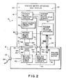
- An electronic postage meter 10 is removably mounted on a postage meter base 12.
- the meter is locked into place by operation lever 14 associated with the base.
- the base 12 is engaged in a manner to provide mechanical drive energy to the printing mechanism of the meter 10, to provide a communications channel via fiber optic links between the computing circuits of the base 12 and the meter 10, and finally, to provide electrical power to the postage meter unit to energize the postage meter computing circuits, keyboard, display and the value selection mechanism of the postage printing mechanism.
- the printing mechanism may either be a mechanical printing mechanism, an ink jet printing mechanism, a matrix pin printing mechanism, or any other suitable printing mechanism.
- the critical circuits within the meter 10 are shielded by a tamper proof housing 16.
- the housing 16 is of the type which prevents electromagnetic radiation, except as is coupled through a predetermined location in the bottom of the meter as shown in Figure 2, from entering the electronic postage meter.
- a slot 18 is provided between the postage meter 10 and the base 12 at the forward edge thereof, for receiving envelopes or the like and printing postage thereon.
- the postage meter is provided with a display panel 20, preferably an electronic display device, as well as a control panel or keyboard 22.
- the postage meter 10 is detachably mounted on the postage meter mailing machine base 12.
- the mailing machine base provides mechanical energy to postage meter printing mechanism 32 via a drive train including drive gear 34 in the postage meter 10 via a mating gear 36 in the mailing machine base.
- the gear 36 is energized to rotate by a motor 38 which is electrically powered from a power supply 40.
- the gearing arrangement may be similar to that shown in U.S. Patent No.
- the mailing machine base 12 includes computing circuits 42 adapted to control the operation of the mailing machine and to provide bi-directional communications with the postage meter computer circuits 44, and if desired, with the postage meter printing mechanism 32.
- the communications may be in accordance with the serial communication echoplex techniques described in U.S. Patent No. 4,301,507 for Electronic Postage Meter Having Plural Computing Systems.
- the communication between the various components is achieved by the utilization of fiber optic cables 46, 48, 50, and 52. Fiber optic cables 50 and 46 are connected by a plug arrangement 54. In a like manner fiber optic cables 48 and 52 are connected by a plug arrangement 56. It should be noted that these plugs can be of the type which are self-engaging when the postage meter 10 is mounted onto the mailing machine base 12 and the locking lever 14 operated.
- the mailing machine is energized when the power switch 26 on the mailing machine base is turned on, allowing the AC line voltage to be coupled to the power supply 40.
- the power supply 40 provides electrical power to the computing circuits 42 and to the motor 38. Additionally, the power supply 40 energizes the primary winding 58 of a portion of a transformer 59.
- a first portion 60 of the transformer 59 is located within the mailing machine base 12.
- a second portion 61 of the transformer 59 is located within the postage meter 10.
- the portions of the transformer in each section cooperate to form a single operative transformer unit having a primary winding, a secondary winding and a two-part core.
- the portion 60 of the transformer 59 in the mailing machine base includes the primary winding 58 energized by the mailing machine power supply 40, a first section 62 of an iron coupling core and a magnetic window 64 in the mailing machine base casing 65.
- the casing 65 for the mailing machine base 12 can be made of a non-magnetizable medium while window 64 is made of a magnetizable medium and in conjunction with the iron core section 62 provides a magnetic path which cooperates with a corresponding magnetic path in the postage meter unit 10.
- the portion 61 of the transformer 59 in the postage meter unit 10 includes a secondary winding 66 which is coupled via saturable core section 68, to a mating magnetic window 70 in the case 16 of the postage meter 10.
- the magnetic window 70 functions in a manner similar to the magnetic window 64.
- the windows 64 and 70 can be nonmagnetic as well as electrically non-conductive, an insulating material or a poor conductor.
- the window can be fabricated from a magnetizable medium with poor conductivity such as certain ferrite material.
- the windows 64 and 70 can be fabricated from non-magnetizable insulating material such as glass or plastics.
- the primary winding 58 With the meter 10 mounted on the mailing machine base 12, and energy applied to the power supply 40, the primary winding 58 is energized. The magnetic flux generated by the primary winding 58 is coupled via the core section 62, the window 64, the window 70 and the core section 68 to the secondary winding 66. This energizes the postage meter power supply 72. If the postage meter power switch 30 is turned on, the postage meter power supply 72, when thus energized, will likewise energize the postage meter printing mechanism 32 and, via an over-voltage protection circuit 74, the postage meter computing circuits 44. When this occurs, and the postage meter keyboard and display are actuated, data stored in the postage meter non-volatile memory 76 is loaded into the postage meter computing circuit 44, and the meter 10 is in condition for operation.
- the postage meter over-voltage protection circuit 74 may also include a detection circuit to detect when power from the postage meter power supply 72 is falling. When power fails or is turned off, the detection circuit triggers the postage meter computing circuits 44 to go into a power down routine and transfer the postage meter accounting information back to the postage meter non-volatile memory 76.
- a storage capacitor is provided in the postage meter power supply 72 to provide a sufficient time to complete the information transfer.
- magnetic energy can enter the meter 10 via the magnetic window 70 and, if sufficient in duration and magnitude, cause the postage meter power supply 72 to be energized.
- magnetic energy can enter the meter 10 via the magnetic window 70 and, if sufficient in duration and magnitude, cause the postage meter power supply 72 to be energized.
- excess amounts of magnetic energy cannot be coupled into the meter, because increasing magnetic energy will not increase the magnetic flux flowing through the saturable core 68. This protects the meter against damage from excessive magnetic energy intentionally or inadvertently being directed against the magnetic window 70 in the postage meter casing 16. It should be recognized that other forms of protection can be provided to avoid coupling excessive energy into the meter, such as the utilization of a very high impedance electrical resistance, and the suitable design of the magnetic circuit.
- protection can be included in the postage meter computing circuit program such that if the postage meter power supply is energized and de-energized more than a predetermined number of times within a predetermined time period the meter can be caused to become inoperative. Additionally, it can be provided that a code to enable the meter for operation and known only to authorized users is required to be input via the postage meter keyboard 22 only when the meter 10 is on the base 12 and an enabling command issued by the mailing machine base computing circuits 42.
- the size of the magnetic circuit can be reduced by utilizing a higher frequency than the 60 or 50 Hertz rate commonly associated with AC line power.
- the frequency at which the primary winding 58 is energized to as high as 100 kilohertz, which is commonly associated with circuit switching power supplies, the size and cost of the magnetic circuit can be reduced.
- the particular operating frequency is a matter of design choice in accordance with the particular design of the mailing machine base power supply 40 and the particular design of the postage meter power supply 72 as well as the transformer 59.
- the non-volatile memory 76 of the postage meter provides for the storage of critical accounting information when the postage meter 10 is not energized.
- This data which for the purposes of the present application is considered to be critical accounting information is written into predetermined physical locations of memory.
- the locations are desirably surface locations easily physically accessed by, for example, the removal of a detachable cover 84. There are a plurality of such locations 78, 80 and 82.
- locations are selected to be both physically accessible and physically locatable areas of the non-volatile memory 76.
- the first location for the critical accounting data 78 is located at one corner of the non-volatile memory while the second location 80 is at another corner of the non-volatile memory.
- the third location 82 is shown as being intermediate to corners of the memory.
- the meter memory should electrically fail for any reason, by having a plurality of predefined physically accessible memory locations storing the critical accounting information, the information can be reconstructed even though the memory is electrically inoperative. Accordingly, an inoperative non-volatile memory 76 is physically removed from the postage meter unit 10 and the predetermined locations 78, 80 and 82 are examined with a scanning microscope to determine the orientation of predetermined memory areas to reconstruct the bit pattern for the critical accounting data. In this way, by reading one location, the data can be reconstructed. By comparing the reconstructed data from the other of the plurality of locations, the level of assurance as to the accuracy as to the reconstructed data is greatly increased.
- an electronic postage meter can be energized by utilizing magnetic energy generated in the postage meter base and magnetically coupled into a sealed meter unit.
- the magnetic circuit designed to energize the postage meter unit is designed to limit the amount of energy which can be coupled from the base of the meter into the meter unit.
- the meter may be powered by magnetic energy which alternates at a rate significantly higher than typical A C line rates of 60 and 50 Hertz. The utilization of high frequency electromagnetic energy allows a reduction in the size of the magnetic circuitry.
- the postage meter may be of the type which includes a non-volatile memory coupled to the postage meter computer and including a plurality of locations for storing accounting data when said postage meter computer is not energized.
- the plurality of locations are in predetermined physical locations which are physically accessible when the memory is removed from the meter so that the locations can be scanned by a scanning device to determine the orientation of bit patterns therein without energizing the non-volatile memory and without physically altering the non-volatile memory structure.
Landscapes
- Physics & Mathematics (AREA)
- Engineering & Computer Science (AREA)
- General Physics & Mathematics (AREA)
- Computer Hardware Design (AREA)
- General Engineering & Computer Science (AREA)
- Mathematical Physics (AREA)
- Theoretical Computer Science (AREA)
- Devices For Checking Fares Or Tickets At Control Points (AREA)
- Indication And Recording Devices For Special Purposes And Tariff Metering Devices (AREA)
Applications Claiming Priority (2)
| Application Number | Priority Date | Filing Date | Title |
|---|---|---|---|
| US06/344,651 US4471440A (en) | 1982-02-01 | 1982-02-01 | Electronic postage meter having power magnetically coupled to the meter from the meter base |
| US344651 | 1982-02-01 |
Publications (4)
| Publication Number | Publication Date |
|---|---|
| EP0086396A2 true EP0086396A2 (de) | 1983-08-24 |
| EP0086396A3 EP0086396A3 (en) | 1985-03-06 |
| EP0086396B1 EP0086396B1 (de) | 1989-02-01 |
| EP0086396B2 EP0086396B2 (de) | 1991-09-11 |
Family
ID=23351403
Family Applications (1)
| Application Number | Title | Priority Date | Filing Date |
|---|---|---|---|
| EP83100932A Expired EP0086396B2 (de) | 1982-02-01 | 1983-02-01 | Frankiermaschinensystem |
Country Status (5)
| Country | Link |
|---|---|
| US (1) | US4471440A (de) |
| EP (1) | EP0086396B2 (de) |
| JP (1) | JPS58169691A (de) |
| CA (1) | CA1197013A (de) |
| DE (1) | DE3379125D1 (de) |
Cited By (2)
| Publication number | Priority date | Publication date | Assignee | Title |
|---|---|---|---|---|
| EP0621562A1 (de) * | 1993-04-21 | 1994-10-26 | Secap | Zweiteilige Frankiermaschine |
| EP0645740A1 (de) * | 1993-09-24 | 1995-03-29 | Neopost Industrie | Frankiermaschine mit einer Schaltung zur Sicherheitsverriegelung |
Families Citing this family (9)
| Publication number | Priority date | Publication date | Assignee | Title |
|---|---|---|---|---|
| US4524426A (en) * | 1983-04-19 | 1985-06-18 | Pitney Bowes Inc. | Electronic postage meter controllable by mailing machine |
| US4578758A (en) * | 1983-06-23 | 1986-03-25 | Pitney Bowes Inc. | Electronic postage meter having a regulated power supply system responsive to a voltage developed in a transformer primary winding circuit |
| EP0165386B1 (de) * | 1984-04-26 | 1989-11-29 | Heidelberger Druckmaschinen Aktiengesellschaft | Verfahren und Speichersystem zum Speichern von Einstellwerten für Stellvorrichtungen an Druckmaschinen |
| US4817002A (en) * | 1984-12-24 | 1989-03-28 | Pitney Bowes Inc. | Electronic postage meter non-volatile memory systems having human visually readable and machine stored data |
| US4876956A (en) * | 1987-10-27 | 1989-10-31 | Pitney Bowes Inc. | Removable postage meter having an indicia cover |
| JP2621414B2 (ja) * | 1988-09-17 | 1997-06-18 | 株式会社日立製作所 | コードレスキーボードを有する情報処理装置 |
| US5109354A (en) * | 1989-03-31 | 1992-04-28 | Kyocera Corporation | Electronic system pocketbook apparatus |
| FR2688930B1 (fr) * | 1992-03-23 | 1995-06-16 | Alcatel Satmam | Dispositif de connexion sans contact electrique. |
| GB2377822A (en) * | 2001-06-15 | 2003-01-22 | Marconi Applied Technologies | Transformer arrangement for delivering low voltage power to a high voltage device |
Family Cites Families (15)
| Publication number | Priority date | Publication date | Assignee | Title |
|---|---|---|---|---|
| US2934009A (en) * | 1956-10-22 | 1960-04-26 | Pitney Bowes Inc | Sheet feeding and treating |
| JPS432922Y1 (de) * | 1964-07-10 | 1968-02-07 | ||
| GB1180168A (en) * | 1967-12-04 | 1970-02-04 | Gen Electric | Battery Charging Arrangement |
| US3764971A (en) * | 1971-08-19 | 1973-10-09 | G Brobeck | Electric alarm device |
| US3938095A (en) * | 1971-11-04 | 1976-02-10 | Pitney-Bowes, Inc. | Computer responsive postage meter |
| US3978457A (en) * | 1974-12-23 | 1976-08-31 | Pitney-Bowes, Inc. | Microcomputerized electronic postage meter system |
| US4004251A (en) * | 1975-11-03 | 1977-01-18 | General Electric Company | Inverter transformer |
| US4310754A (en) * | 1976-07-14 | 1982-01-12 | Pitney Bowes Inc. | Communication means with transducer physically spaced from interior wall of secure housing |
| DE2752783C2 (de) * | 1977-11-25 | 1979-08-30 | Siemens Ag, 1000 Berlin Und 8000 Muenchen | Gerät zum Erfassen und Verarbeiten von elektrischen Signalen |
| FR2420832A1 (fr) * | 1978-03-23 | 1979-10-19 | Roland Emballages | Procede et dispositif pour la transmission d'energie electrique a travers une paroi |
| US4285050A (en) * | 1979-10-30 | 1981-08-18 | Pitney Bowes Inc. | Electronic postage meter operating voltage variation sensing system |
| GB2063160B (en) * | 1979-10-30 | 1984-01-11 | Pitney Bowes Inc | Electronic postage meter |
| US4301507A (en) * | 1979-10-30 | 1981-11-17 | Pitney Bowes Inc. | Electronic postage meter having plural computing systems |
| US4310755A (en) * | 1979-12-26 | 1982-01-12 | Pitney Bowes Inc. | Electronic postage meter radiant energy device circuit |
| JPS56147380A (en) * | 1980-04-15 | 1981-11-16 | Matsushita Electric Works Ltd | Illuminator |
-
1982
- 1982-02-01 US US06/344,651 patent/US4471440A/en not_active Expired - Lifetime
-
1983
- 1983-01-31 CA CA000420626A patent/CA1197013A/en not_active Expired
- 1983-02-01 EP EP83100932A patent/EP0086396B2/de not_active Expired
- 1983-02-01 DE DE8383100932T patent/DE3379125D1/de not_active Expired
- 1983-02-01 JP JP58015376A patent/JPS58169691A/ja active Pending
Cited By (6)
| Publication number | Priority date | Publication date | Assignee | Title |
|---|---|---|---|---|
| EP0621562A1 (de) * | 1993-04-21 | 1994-10-26 | Secap | Zweiteilige Frankiermaschine |
| FR2704343A1 (fr) * | 1993-04-21 | 1994-10-28 | Secap | Machine à affranchir en deux parties. |
| US5586035A (en) * | 1993-04-21 | 1996-12-17 | Secap | Franking machine in two portions |
| EP0645740A1 (de) * | 1993-09-24 | 1995-03-29 | Neopost Industrie | Frankiermaschine mit einer Schaltung zur Sicherheitsverriegelung |
| FR2710435A1 (fr) * | 1993-09-24 | 1995-03-31 | Neopost Ind | Machine à affranchir comportant un circuit de verrouillage de sécurité. |
| US5486973A (en) * | 1993-09-24 | 1996-01-23 | Neopost Industrie | Postage meter including a safety locking circuit |
Also Published As
| Publication number | Publication date |
|---|---|
| CA1197013A (en) | 1985-11-19 |
| EP0086396B1 (de) | 1989-02-01 |
| EP0086396A3 (en) | 1985-03-06 |
| EP0086396B2 (de) | 1991-09-11 |
| US4471440A (en) | 1984-09-11 |
| JPS58169691A (ja) | 1983-10-06 |
| DE3379125D1 (de) | 1989-03-09 |
Similar Documents
| Publication | Publication Date | Title |
|---|---|---|
| US4809185A (en) | Secure metering device storage vault for a value printing system | |
| US4240030A (en) | Intelligent electric utility meter | |
| US4471440A (en) | Electronic postage meter having power magnetically coupled to the meter from the meter base | |
| JP2795988B2 (ja) | 郵便料金を印刷するためのプリンタの制御方法 | |
| EP0075825B1 (de) | Elektronisches Postgebührenfeststellsystem | |
| CA1149957A (en) | Electronic postage meter operating voltage variation sensing system | |
| CA1273109A (en) | Secured printer for a value printing system | |
| US3938095A (en) | Computer responsive postage meter | |
| DE3613007B4 (de) | System zur Ermittlung von nicht-abgerechneten Drucken | |
| EP0099571B1 (de) | Gehäuse für eine elektronische Vorrichtung wie zum Beispiel eine Frankiermaschine | |
| US4421977A (en) | Security system for electronic device | |
| CA1223361A (en) | Electronic postage meter controllable by mailing machine | |
| CA2071839C (en) | Postage-meter-strip printing machine | |
| USRE31875E (en) | Computer responsive postage meter | |
| US4472781A (en) | Power supply system | |
| CA1210510A (en) | Electronic postage meter having a one time actuable operating program to enable setting of critical accounting registers to predetermined values | |
| US4578758A (en) | Electronic postage meter having a regulated power supply system responsive to a voltage developed in a transformer primary winding circuit | |
| CA1147468A (en) | Electronic postage meter having keyboard entered combination for recharging | |
| US4862375A (en) | Magnetic power coupler for a vault cartridge | |
| CA1211790A (en) | Power supply system | |
| EP0788077A2 (de) | Apparat zum Frankieren von Poststücken | |
| CA1061466A (en) | Computer responsive postage meter | |
| EP0430646B1 (de) | Frankiermaschine | |
| GB1581680A (en) | Postal franking machine | |
| CA1061904A (en) | Computer responsive postage meter |
Legal Events
| Date | Code | Title | Description |
|---|---|---|---|
| PUAI | Public reference made under article 153(3) epc to a published international application that has entered the european phase |
Free format text: ORIGINAL CODE: 0009012 |
|
| PUAI | Public reference made under article 153(3) epc to a published international application that has entered the european phase |
Free format text: ORIGINAL CODE: 0009012 |
|
| AK | Designated contracting states |
Designated state(s): BE CH DE FR GB LI NL |
|
| PUAL | Search report despatched |
Free format text: ORIGINAL CODE: 0009013 |
|
| AK | Designated contracting states |
Designated state(s): BE CH DE FR GB LI NL |
|
| 17P | Request for examination filed |
Effective date: 19850806 |
|
| 17Q | First examination report despatched |
Effective date: 19860520 |
|
| RAP1 | Party data changed (applicant data changed or rights of an application transferred) |
Owner name: PITNEY BOWES INC. |
|
| R17C | First examination report despatched (corrected) |
Effective date: 19870127 |
|
| GRAA | (expected) grant |
Free format text: ORIGINAL CODE: 0009210 |
|
| AK | Designated contracting states |
Kind code of ref document: B1 Designated state(s): BE CH DE FR GB LI NL |
|
| REF | Corresponds to: |
Ref document number: 3379125 Country of ref document: DE Date of ref document: 19890309 |
|
| ET | Fr: translation filed | ||
| PLBI | Opposition filed |
Free format text: ORIGINAL CODE: 0009260 |
|
| 26 | Opposition filed |
Opponent name: FRANCOTYP- POSTALIA GMBH Effective date: 19891102 |
|
| NLR1 | Nl: opposition has been filed with the epo |
Opponent name: FRANCOTYP- POSTALIA GMBH |
|
| PUAH | Patent maintained in amended form |
Free format text: ORIGINAL CODE: 0009272 |
|
| STAA | Information on the status of an ep patent application or granted ep patent |
Free format text: STATUS: PATENT MAINTAINED AS AMENDED |
|
| 27A | Patent maintained in amended form |
Effective date: 19910911 |
|
| AK | Designated contracting states |
Kind code of ref document: B2 Designated state(s): BE CH DE FR GB LI NL |
|
| NLR2 | Nl: decision of opposition | ||
| NLR3 | Nl: receipt of modified translations in the netherlands language after an opposition procedure | ||
| ET3 | Fr: translation filed ** decision concerning opposition | ||
| PGFP | Annual fee paid to national office [announced via postgrant information from national office to epo] |
Ref country code: BE Payment date: 19930105 Year of fee payment: 11 |
|
| PGFP | Annual fee paid to national office [announced via postgrant information from national office to epo] |
Ref country code: NL Payment date: 19930228 Year of fee payment: 11 |
|
| PG25 | Lapsed in a contracting state [announced via postgrant information from national office to epo] |
Ref country code: BE Effective date: 19940228 |
|
| BERE | Be: lapsed |
Owner name: PITNEY BOWES INC. Effective date: 19940228 |
|
| PG25 | Lapsed in a contracting state [announced via postgrant information from national office to epo] |
Ref country code: NL Effective date: 19940901 |
|
| NLV4 | Nl: lapsed or anulled due to non-payment of the annual fee | ||
| REG | Reference to a national code |
Ref country code: GB Ref legal event code: IF02 |
|
| PGFP | Annual fee paid to national office [announced via postgrant information from national office to epo] |
Ref country code: FR Payment date: 20020117 Year of fee payment: 20 |
|
| PGFP | Annual fee paid to national office [announced via postgrant information from national office to epo] |
Ref country code: DE Payment date: 20020118 Year of fee payment: 20 |
|
| PGFP | Annual fee paid to national office [announced via postgrant information from national office to epo] |
Ref country code: GB Payment date: 20020121 Year of fee payment: 20 Ref country code: CH Payment date: 20020121 Year of fee payment: 20 |
|
| PG25 | Lapsed in a contracting state [announced via postgrant information from national office to epo] |
Ref country code: LI Free format text: LAPSE BECAUSE OF EXPIRATION OF PROTECTION Effective date: 20030131 Ref country code: GB Free format text: LAPSE BECAUSE OF EXPIRATION OF PROTECTION Effective date: 20030131 Ref country code: CH Free format text: LAPSE BECAUSE OF EXPIRATION OF PROTECTION Effective date: 20030131 |
|
| REG | Reference to a national code |
Ref country code: GB Ref legal event code: PE20 Effective date: 20030131 |
|
| REG | Reference to a national code |
Ref country code: CH Ref legal event code: PL |
|
| PLAB | Opposition data, opponent's data or that of the opponent's representative modified |
Free format text: ORIGINAL CODE: 0009299OPPO |