EP0086414B1 - Accessoire pour ceintures de sécurité de véhicules à enrouleur automotique - Google Patents
Accessoire pour ceintures de sécurité de véhicules à enrouleur automotique Download PDFInfo
- Publication number
- EP0086414B1 EP0086414B1 EP83101062A EP83101062A EP0086414B1 EP 0086414 B1 EP0086414 B1 EP 0086414B1 EP 83101062 A EP83101062 A EP 83101062A EP 83101062 A EP83101062 A EP 83101062A EP 0086414 B1 EP0086414 B1 EP 0086414B1
- Authority
- EP
- European Patent Office
- Prior art keywords
- base plate
- belt
- auxiliary device
- belts
- additional
- Prior art date
- Legal status (The legal status is an assumption and is not a legal conclusion. Google has not performed a legal analysis and makes no representation as to the accuracy of the status listed.)
- Expired
Links
- 230000000452 restraining effect Effects 0.000 description 4
- 206010040007 Sense of oppression Diseases 0.000 description 1
- 229910000639 Spring steel Inorganic materials 0.000 description 1
- 229910000831 Steel Inorganic materials 0.000 description 1
- 230000001133 acceleration Effects 0.000 description 1
- 239000013013 elastic material Substances 0.000 description 1
- 230000014759 maintenance of location Effects 0.000 description 1
- 210000000056 organ Anatomy 0.000 description 1
- 239000010959 steel Substances 0.000 description 1
Images
Classifications
-
- B—PERFORMING OPERATIONS; TRANSPORTING
- B60—VEHICLES IN GENERAL
- B60R—VEHICLES, VEHICLE FITTINGS, OR VEHICLE PARTS, NOT OTHERWISE PROVIDED FOR
- B60R22/00—Safety belts or body harnesses in vehicles
- B60R22/18—Anchoring devices
- B60R22/19—Anchoring devices with means for reducing belt tension during use under normal conditions
Definitions
- the present invention relates to an additional device for motor vehicle seat belts with an automatic rewinding device, with a base plate and a movable clamping part arranged thereon, and at least one belt deflector as a fastening point for the base plate.
- Such short belt channels are still used by certain automobile manufacturers. Mandiese also finds relatively long free distances of 10 and more cm with belts that have been installed subsequently.
- automobile types have also become known in which the free distance between the upper outlet from the belt channel and the deflection point is only a few cm.
- the deflection device is arranged directly concealed in bodywork shafts, the belts being guided to the outside only through a relatively narrow gap.
- the known additional devices are not suitable for attachment to long guide channels or closed guide channels, as are provided in particular in more expensive automobiles.
- the present invention aims to create a universally usable additional device which can be easily adapted to all belt systems that have become known.
- Such an additional device is characterized in that a hook-shaped additional organ, for. B. an additional clamp is provided, which makes it possible to connect the base plate with the belt deflector.
- the system for motor vehicle seat belts with an automatic rewind device comprises a spring-loaded roller 1 in a housing 2, which is fastened to a body 3 of a vehicle.
- the spring-loaded roller 1 serves to accommodate a restraint belt 40, the behavior of which will be explained in detail later.
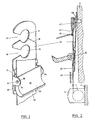
- the additional device which allows the restraint belts 40 to be passed over the chest of the driver to be belted in a loose state, has a base plate 10 with two openings 11 and 12 lying one above the other.
- the openings 11 and 12 are open via an extension 13 and 14 on one side. These openings 11 and 12 serve to hold the base plate 10 to a body part.
- the web lying between the two openings 11 and 12 is so flexible that the corresponding extension 13 or 14 can be stretched for pushing on the plate 10 without this leading to the plate 10 breaking.
- the base plate 10 is also provided with a parting line 16, which allows the upper part to be broken away when the lower opening 12 is used, so that it does not interfere with the attachment of the remaining additional device. According to FIGS.
- FIG. 2 shows part of a car interior, a relatively long belt channel 43 being provided, but which does not extend as far as a fastening screw 46 provided in the body.
- a fastening screw 46 provided in the body.
- the screw 46 can be covered by means of a plastic cover 47 for a better appearance.
- the additional device can be fastened to the upper opening 11. If the belt channel is guided all the way to the fastening screw 46, the additional device must be attached to the belt deflection 42 with the additional clamp, as described subsequently.
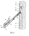
- a vehicle-side belt channel 44 is provided in the sense of FIG. 7.
- the channel 44 has a slot 45 at the usual height for leading the belts 40 out.
- the fastening screw 46 is fastened here in the interior of the belt channel 44.
- an additional clip 50 which has a flanged, preferably segmented edge 51 and an upper hook 53 in the form of a hook.
- the edge 51 and the hanger 53 form two clamping elements.
- the attachment of such a clip 50 is indicated in FIGS. 3 and 6.
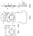
- This clip 50 can be made of an elastic material, e.g. B. sheet steel, plastic or the like. It allows the front part of the base plate 10 with the clamp 50 mounted thereon and this structure to be suspended by means of the upper hanger 53 around the deflector 42. The restraint belts 40 are then passed over the upper hanger 53 and the clamps 50 and then get between the clamping part 30 and the base plate 10.
- the clamping part 30 in the bearing blocks 24 is pivoted by 180 ° with respect to the position according to FIG. 2, such that a train on the restraining belts 40 in the direction of the arrow pivots the clamping part 30 and the clamping surface 35 except Engagement with the straps 40 brings.
- the restraining belts 40 are in turn freely movable. It is in turn under the tension of the spring-loaded roller 1.
- This version of the additional device with the spring steel sheet can be attached to all previously known motor vehicle seat belt systems.
- the base plate In the case of very short belt channels, the base plate is hung in the upper opening 11, in the case of longer ones in the opening 12, the upper part of the base plate 10 being broken off at the parting line 16, and in the case of belts which are completely installed on the vehicle, with belt channels 44, as shown in FIG. 7 shows, the additional device is arranged by hanging in the manner shown in Fig. In any case, a pull on the restraining belts 40 against the spring force of the roll 1 is sufficient to free it from the retention by means of the clamping part 30 and in turn place it under the pull of the automatic rewinding device.
- the analogous arrangement takes place when the deflection carrier 41 with deflector 42 above, for. B. on the roof, or when the slot 45 is in the roof.
Landscapes
- Engineering & Computer Science (AREA)
- Mechanical Engineering (AREA)
- Automotive Seat Belt Assembly (AREA)
- Massaging Devices (AREA)
- Pens And Brushes (AREA)
- Finger-Pressure Massage (AREA)
Claims (5)
Priority Applications (1)
| Application Number | Priority Date | Filing Date | Title |
|---|---|---|---|
| AT83101062T ATE21228T1 (de) | 1982-02-12 | 1983-02-04 | Zusatzvorrichtung fuer kraftfahrzeugsicherheitsgurte mit automatischer rueckspulvorrichtung. |
Applications Claiming Priority (2)
| Application Number | Priority Date | Filing Date | Title |
|---|---|---|---|
| CH87382 | 1982-02-12 | ||
| CH873/82 | 1982-02-12 |
Publications (2)
| Publication Number | Publication Date |
|---|---|
| EP0086414A1 EP0086414A1 (fr) | 1983-08-24 |
| EP0086414B1 true EP0086414B1 (fr) | 1986-08-06 |
Family
ID=4197159
Family Applications (1)
| Application Number | Title | Priority Date | Filing Date |
|---|---|---|---|
| EP83101062A Expired EP0086414B1 (fr) | 1982-02-12 | 1983-02-04 | Accessoire pour ceintures de sécurité de véhicules à enrouleur automotique |
Country Status (7)
| Country | Link |
|---|---|
| US (1) | US4484766A (fr) |
| EP (1) | EP0086414B1 (fr) |
| JP (1) | JPS5977869A (fr) |
| AT (1) | ATE21228T1 (fr) |
| AU (1) | AU1093483A (fr) |
| CA (1) | CA1194460A (fr) |
| DE (1) | DE3365044D1 (fr) |
Families Citing this family (16)
| Publication number | Priority date | Publication date | Assignee | Title |
|---|---|---|---|---|
| US5286057A (en) * | 1982-09-08 | 1994-02-15 | Forster Lloyd M | Comfort feature |
| GB8400444D0 (en) * | 1984-01-09 | 1984-02-08 | Pz Prod Ltd | Control device for inertia reel seat belt |
| DE3429005A1 (de) * | 1984-08-07 | 1986-04-10 | Peter Prof. Dr.-Ing. 8208 Kolbermoor Herberholz | Kraftfahrzeug - insassen - sicherheitsgurtsystem |
| JPS6222168U (fr) * | 1985-07-25 | 1987-02-10 | ||
| US4726625A (en) * | 1986-07-07 | 1988-02-23 | Indiana Mills & Manufacturing, Inc. | Belt retraction cam lock |
| JPS63100354U (fr) * | 1986-11-28 | 1988-06-29 | ||
| FR2627731A1 (fr) * | 1988-02-29 | 1989-09-01 | Mottin Nicole | Dispositif de reglage d'une ceinture de securite |
| US5139282A (en) * | 1991-05-06 | 1992-08-18 | General Motors Corporation | Shoulder belt comfort spring |
| US5730500A (en) * | 1996-12-11 | 1998-03-24 | Kinedyne Corporation | Shoulder belt height adjuster |
| DE19721229B4 (de) * | 1997-05-21 | 2005-05-04 | Dr.Ing.H.C. F. Porsche Ag | Verschluß für ein Verdeck eines Fahrzeuges, insbesondere eines Personenkraftwagens |
| US6260884B1 (en) * | 1999-03-05 | 2001-07-17 | Indiana Mills & Manufacturing, Inc. | D-loop web belt gripper |
| GB2373762B (en) * | 2001-03-28 | 2004-02-11 | Martin Baker Aircraft Co Ltd | A harness arrangement for a seat and an inertia reel arrangement |
| WO2005051731A1 (fr) * | 2003-11-25 | 2005-06-09 | Patricio Orozco Loza | Amelioration apportee a une ceinture de securite pour vehicules |
| US20060157967A1 (en) * | 2005-01-14 | 2006-07-20 | Edwards Paul R | Seat belt system for automobile |
| US20130127230A1 (en) * | 2011-11-21 | 2013-05-23 | Anthony Fini | Vehicle shoulder belt extension |
| AU2013202975B2 (en) * | 2012-05-09 | 2015-07-16 | Britax Childcare Pty Ltd | Seat belt lock-off for a safety seat |
Family Cites Families (11)
| Publication number | Priority date | Publication date | Assignee | Title |
|---|---|---|---|---|
| DE2047706C3 (de) * | 1970-09-28 | 1979-01-25 | Wolf-Dieter 7071 Lindach Klink | Sicherheitsgurt für Insassen von Kraftfahrzeugen |
| US3695697A (en) * | 1970-10-08 | 1972-10-03 | Allied Chem | Controlled memory keeper |
| US4209142A (en) * | 1975-05-02 | 1980-06-24 | Allied Chemical Corporation | Remote tension-relieving apparatus for safety belt retractor |
| US3981052A (en) * | 1975-07-23 | 1976-09-21 | The Firestone Tire & Rubber Company | Low friction guide loop |
| JPS5236943U (fr) * | 1975-09-08 | 1977-03-16 | ||
| CH600900A5 (en) * | 1976-08-24 | 1978-06-30 | Ernst Flueck | Vehicle seat belt tensioning system |
| US4136422A (en) * | 1977-04-22 | 1979-01-30 | Ivanov Jury N | Tensioning and locking strap device |
| GB2005130B (en) * | 1977-09-26 | 1982-05-12 | Oxley D A J | Control device for an inertia-type seat belt |
| JPS54143524U (fr) * | 1978-03-28 | 1979-10-05 | ||
| FR2427103A1 (fr) * | 1978-05-30 | 1979-12-28 | Duperray Jacques | Appareil accessoire limitant la course des ceintures de securite a enrouleur |
| FR2475905B1 (fr) * | 1980-01-11 | 1987-02-13 | Alix Maurice | Butee de tension pour ceinture de securite du type a enrouleur |
-
1983
- 1983-01-19 JP JP58007194A patent/JPS5977869A/ja active Pending
- 1983-01-24 CA CA000420089A patent/CA1194460A/fr not_active Expired
- 1983-01-27 US US06/461,355 patent/US4484766A/en not_active Expired - Fee Related
- 1983-02-02 AU AU10934/83A patent/AU1093483A/en not_active Abandoned
- 1983-02-04 EP EP83101062A patent/EP0086414B1/fr not_active Expired
- 1983-02-04 AT AT83101062T patent/ATE21228T1/de not_active IP Right Cessation
- 1983-02-04 DE DE8383101062T patent/DE3365044D1/de not_active Expired
Also Published As
| Publication number | Publication date |
|---|---|
| US4484766A (en) | 1984-11-27 |
| AU1093483A (en) | 1983-08-18 |
| EP0086414A1 (fr) | 1983-08-24 |
| JPS5977869A (ja) | 1984-05-04 |
| DE3365044D1 (en) | 1986-09-11 |
| ATE21228T1 (de) | 1986-08-15 |
| CA1194460A (fr) | 1985-10-01 |
Similar Documents
| Publication | Publication Date | Title |
|---|---|---|
| EP0086414B1 (fr) | Accessoire pour ceintures de sécurité de véhicules à enrouleur automotique | |
| DE69805568T2 (de) | Luftsack-Gehäuseeinrichtung | |
| DE4341119A1 (de) | Vormontierte Trägereinheit für die Funktionsteile eines Sicherheitsgurtsystems | |
| DE4122372A1 (de) | Freifallende gurtzunge | |
| DE3032170A1 (de) | Umlenkbeschlag mit klemmvorrichtung fuer einen sicherheitsgurt in kraftfahrzeugen | |
| EP0743229B1 (fr) | Couvercle de sac gonflable pour un système de retenue d'un occupant de véhicule | |
| DE3242783A1 (de) | Einziehvorrichtung fuer sicherheitsgurte mit einer zugkraft ansprechenden sperreinrichtung | |
| DE4139010B4 (de) | Verfahren zur Montage einer Schnapp- bzw. Klipsverbindung | |
| DE2634218C3 (de) | Vorrichtung zur Befestigung eines Sicherheitsgurtes | |
| DE3325988A1 (de) | Klemmvorrichtung zum klemmen eines sitzgurtes | |
| DE4343531C2 (de) | Sicherheitsgurtvorrichtung | |
| DE69101985T2 (de) | Sicherheitsgurtaufroller. | |
| EP0582107B1 (fr) | Colonne de direction d'un véhicule à moteur avec dispositif de rétractation pour la zone terminale du côté du volant | |
| EP0300470A1 (fr) | Dispositif de couplage d'un support muni d'un dispositif d'accrochage pour ceinture de sécurité sur une pièce d'attache fixée au véhicule | |
| DE2819018C2 (de) | Schloßbefestigung für Sicherheitsgurte in Fahrzeugen | |
| DE69509481T2 (de) | Vorrichtung zum Verankern eines Kraftfahrzeug-Sicherheitsgurtendes | |
| DE2360702A1 (de) | Sicherheitsgurtanordnung fuer fahrzeuge, insbesondere personenkraftfahrzeuge | |
| DE2752860A1 (de) | Klemmvorrichtung fuer einen sicherheitsgurt und rueckhaltesystem | |
| DE202023107128U1 (de) | Sicherheitssystem für ein Fahrzeug | |
| DE2954062C2 (de) | Passive Sicherheitsgurtvorrichtung für ein Fahrzeug | |
| DE60302871T2 (de) | Eine Sicherheitsgurtvorrichtung | |
| DE2935842C2 (de) | Passives Sicherheitsgurtsystem | |
| DE2613654A1 (de) | Vorrichtung zur hoehenverstellbaren halterung eines befestigungs- oder umlenkbeschlages eines sicherheitsgutes | |
| DE2850758A1 (de) | Automatischer gurtbandaufroller fuer sicherheitsgurte, insbesondere in kraftfahrzeugen | |
| DE2601171C2 (de) | Sicherheitsgurtanordnung, insbesondere für Kraftfahrzeuge |
Legal Events
| Date | Code | Title | Description |
|---|---|---|---|
| PUAI | Public reference made under article 153(3) epc to a published international application that has entered the european phase |
Free format text: ORIGINAL CODE: 0009012 |
|
| PUAI | Public reference made under article 153(3) epc to a published international application that has entered the european phase |
Free format text: ORIGINAL CODE: 0009012 |
|
| AK | Designated contracting states |
Designated state(s): AT BE CH DE FR GB IT LI LU NL SE |
|
| 17P | Request for examination filed |
Effective date: 19840204 |
|
| GRAA | (expected) grant |
Free format text: ORIGINAL CODE: 0009210 |
|
| AK | Designated contracting states |
Kind code of ref document: B1 Designated state(s): AT BE CH DE FR GB IT LI LU NL SE |
|
| REF | Corresponds to: |
Ref document number: 21228 Country of ref document: AT Date of ref document: 19860815 Kind code of ref document: T |
|
| REF | Corresponds to: |
Ref document number: 3365044 Country of ref document: DE Date of ref document: 19860911 |
|
| ET | Fr: translation filed | ||
| ITF | It: translation for a ep patent filed | ||
| PG25 | Lapsed in a contracting state [announced via postgrant information from national office to epo] |
Ref country code: LU Free format text: LAPSE BECAUSE OF NON-PAYMENT OF DUE FEES Effective date: 19870228 |
|
| PLBE | No opposition filed within time limit |
Free format text: ORIGINAL CODE: 0009261 |
|
| STAA | Information on the status of an ep patent application or granted ep patent |
Free format text: STATUS: NO OPPOSITION FILED WITHIN TIME LIMIT |
|
| 26N | No opposition filed | ||
| PGFP | Annual fee paid to national office [announced via postgrant information from national office to epo] |
Ref country code: SE Payment date: 19900205 Year of fee payment: 8 |
|
| PGFP | Annual fee paid to national office [announced via postgrant information from national office to epo] |
Ref country code: FR Payment date: 19900221 Year of fee payment: 8 |
|
| PGFP | Annual fee paid to national office [announced via postgrant information from national office to epo] |
Ref country code: LU Payment date: 19900222 Year of fee payment: 8 Ref country code: DE Payment date: 19900222 Year of fee payment: 8 |
|
| PGFP | Annual fee paid to national office [announced via postgrant information from national office to epo] |
Ref country code: BE Payment date: 19900223 Year of fee payment: 8 |
|
| PGFP | Annual fee paid to national office [announced via postgrant information from national office to epo] |
Ref country code: AT Payment date: 19900226 Year of fee payment: 8 |
|
| ITTA | It: last paid annual fee | ||
| PGFP | Annual fee paid to national office [announced via postgrant information from national office to epo] |
Ref country code: NL Payment date: 19900228 Year of fee payment: 8 Ref country code: GB Payment date: 19900228 Year of fee payment: 8 |
|
| PGFP | Annual fee paid to national office [announced via postgrant information from national office to epo] |
Ref country code: CH Payment date: 19900430 Year of fee payment: 8 |
|
| PG25 | Lapsed in a contracting state [announced via postgrant information from national office to epo] |
Ref country code: GB Effective date: 19910204 Ref country code: AT Effective date: 19910204 |
|
| PG25 | Lapsed in a contracting state [announced via postgrant information from national office to epo] |
Ref country code: SE Effective date: 19910205 |
|
| PG25 | Lapsed in a contracting state [announced via postgrant information from national office to epo] |
Ref country code: LI Effective date: 19910228 Ref country code: CH Effective date: 19910228 Ref country code: BE Effective date: 19910228 |
|
| PG25 | Lapsed in a contracting state [announced via postgrant information from national office to epo] |
Ref country code: NL Effective date: 19910901 |
|
| GBPC | Gb: european patent ceased through non-payment of renewal fee | ||
| NLV4 | Nl: lapsed or anulled due to non-payment of the annual fee | ||
| PG25 | Lapsed in a contracting state [announced via postgrant information from national office to epo] |
Ref country code: FR Effective date: 19911031 |
|
| REG | Reference to a national code |
Ref country code: CH Ref legal event code: PL |
|
| PG25 | Lapsed in a contracting state [announced via postgrant information from national office to epo] |
Ref country code: DE Effective date: 19911101 |
|
| REG | Reference to a national code |
Ref country code: FR Ref legal event code: ST |
|
| EUG | Se: european patent has lapsed |
Ref document number: 83101062.4 Effective date: 19911008 |