EP0086429A2 - Procédé de cardiogoniométrie et cardiogoniomètre correspondant - Google Patents
Procédé de cardiogoniométrie et cardiogoniomètre correspondant Download PDFInfo
- Publication number
- EP0086429A2 EP0086429A2 EP83101139A EP83101139A EP0086429A2 EP 0086429 A2 EP0086429 A2 EP 0086429A2 EP 83101139 A EP83101139 A EP 83101139A EP 83101139 A EP83101139 A EP 83101139A EP 0086429 A2 EP0086429 A2 EP 0086429A2
- Authority
- EP
- European Patent Office
- Prior art keywords
- electrode
- vector
- electrodes
- cardiogoniometer
- distance
- Prior art date
- Legal status (The legal status is an assumption and is not a legal conclusion. Google has not performed a legal analysis and makes no representation as to the accuracy of the status listed.)
- Granted
Links
Images


Classifications
-
- A—HUMAN NECESSITIES
- A61—MEDICAL OR VETERINARY SCIENCE; HYGIENE
- A61B—DIAGNOSIS; SURGERY; IDENTIFICATION
- A61B5/00—Measuring for diagnostic purposes; Identification of persons
- A61B5/24—Detecting, measuring or recording bioelectric or biomagnetic signals of the body or parts thereof
- A61B5/316—Modalities, i.e. specific diagnostic methods
- A61B5/318—Heart-related electrical modalities, e.g. electrocardiography [ECG]
- A61B5/339—Displays specially adapted therefor
- A61B5/341—Vectorcardiography [VCG]
-
- A—HUMAN NECESSITIES
- A61—MEDICAL OR VETERINARY SCIENCE; HYGIENE
- A61B—DIAGNOSIS; SURGERY; IDENTIFICATION
- A61B5/00—Measuring for diagnostic purposes; Identification of persons
- A61B5/24—Detecting, measuring or recording bioelectric or biomagnetic signals of the body or parts thereof
- A61B5/316—Modalities, i.e. specific diagnostic methods
- A61B5/318—Heart-related electrical modalities, e.g. electrocardiography [ECG]
- A61B5/327—Generation of artificial ECG signals based on measured signals, e.g. to compensate for missing leads
Definitions
- the invention is in the field of cardiography, in particular vector cardiography, and relates to a method for cardiogoniometry, the spatial vector representation of electrical variables of the heart and a cardiogoniometer for processing these electrical variables and for representing parameters derived therefrom for the diagnosis of heart diseases.
- the evaluation of an EKG also includes the determination of the maximum vector of the electrical QRS size in the frontal plane. It finds its expression in the terms left position, steep position, etc. Also the Direction of the repolarization vector, ie the behavior of the electrically detectable T-wave is observed, especially with regard to the direction of the QRS vector (concordant or discordant behavior of the T-wave). The behavior of R and T in the course of a myocardial infarction and its repair serve as an example.
- these assessments are only possible in rough quality and, moreover, are often falsified by errors due to projection, because they are based only on the projection of these vectors onto a plane, but do not take into account the deviation thereof perpendicular to this plane.
- a conclusive assessment is therefore not possible without knowing the behavior of the two associated vectors in space.
- a three-dimensional or orthogonal derivation system must therefore be used for more precise information and for the quantitative detection of changes in the maximum vectors of QRS and T.
- Every bipolar derivative represents the direct projection of the dipole moment of the heart. This cannot be right, because each derivative is just a potential difference measurement, i.e. an undirected variable ⁇ .h. represents a scalar quantity, whereas the dipole moment, in addition to its magnitude, also has a defined direction, i.e. has a vector character (Irnich 1976).
- the path to a new model of the dipole moment opens when one turns away from the individual derivative and takes the electrical conditions into account as a whole in a plane formed by three derivation points. If one uses the term closed mesh in the EKG, for example in the form of Nehb's leads D, A, J, and considers the electrical conditions in this triangle, the size of the excursions of the electrocardiograph can be approximated to a relative measure for the size of the dipole moment are closed. Of course, the simultaneous swings, whether large or small, will always add up to zero, according to the Kirchhoff mesh rule indicated above. But if you now consider the potential differences given by the three derivatives as sub-vectors and add them all together according to the rules ........................7-8 .................
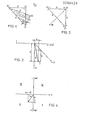
- Figure 1 shows the four-point derivation system according to the invention.
- the tetrahedral lead system to be understood in the spatial sense shows the four electrode attachment points E1, E2, E3 and E4.
- These derivation points are connected as follows: (E1, E2) as an inferior pair I, where E1 corresponds to point V4 according to Wilson, namely 5 ICR (intercostal space) and MCL (medioclavicular line), and point E2 lying sagittal to E1 corresponds to point V8 according to Wilson.
- Perpendicular to point E1 is at a distance of times E1 E2 the derivation point E3; this derivative is the vertical one, labeled V.
- the horizontal pair of leads labeled H (E3, E4) is horizontal to the right side of the patient at a distance of 1 / times E1: E2 arranged. Then there is the dorsal lead (D2, E4) and the anterior lead (A1), the distance between which is determined by the above-mentioned proportions.
- An additional solder from the derivation point E3 to the anterior is designated z o .
- a / I forms the oblique-sagittal x, y plane, Z / A the frontal y, z plane and Z / I the z, x plane.
- the pairing of the derivation points (E2, E3) is not considered to belong to an unused level nor to be considered as a redundant pair. However, this does not mean that diagnostically relevant information cannot be derived from this derivation.
- Two derivation points namely E3 and E2 are relatively uncritical in their relative position to the patient's heart, ie manipulation scatter within certain limits when the electrodes are applied each lead to the same end result.
- the derivation point with the electrode comes perpendicular to the tip of the heart electrode E1 - the position of which has to be determined quite precisely, by the way - on relatively displaceable tissue E3 to lie.
- this derivation point E3 is shifted to a different position relative to the geometry applied and thus also to the heart.
- this does not lead to incorrect measurements, so that the electrode E3 which is most exposed to the positional shifts can be regarded as an electrically adaptive electrode.
- Electrodes on the patient This is a preferred procedure for creating the. Electrodes on the patient. It should also be pointed out that for cardiac diagnosis in animals, only the geometric electrode configuration for the specific animal, which is applicable to the derivation, must be used, and only the coordinate transformation level must be provided with adequate parameters for the determination of the orthogonal derivations. The invention is therefore equally suitable for the heart diagnosis of humans and animals.
- the vector loop in healthy people runs from the top right to the front bottom left and after turning backwards back to the front top right, i.e. the vector loop lies more or less in or parallel to a plane inclined to the sagittal (according to FIG. 1, the area between the three derivation points El, E2 and E4).
- ECG recordings in this level must therefore react very sensitively to changes in the vector loop, which has been confirmed on far more than 2000 ECG measurements.
- This plane becomes perpendicular to the construction of two other projections x and y and the frontal plane are used to construct the projection z o which is perpendicular to the Nehb plane.
- the third axis in the orthogonal system requires an additional vector projection that is perpendicular to these two axes.
- This projection z o is obtained by the derivative in the frontal triangle of the points E1, E3, E4, the points E1 and E4 representing the front derivative points of the oblique-sagittal triangle.
- Point E3 becomes chosen so that its distance from the points E1 and E4 is the same and there is a right angle between these two lines, as shown in FIG. This gives you a right-angled, isosceles triangle.
- the following derivatives apply in this triangle:, the horizontal derivative H from point E4 to point E3, the vertical derivative V from point E3 to point E1 and the anterior derivative A from point E1 to point E4, which is inclined-sagittal with derivative A.
- Triangle D, A, I is identical.
- a vector can be constructed according to the same process, by lining up the simultaneous deflections of the three derivatives in a sign-correct and axis-correct manner for the vector summation.
- What is interested in this sum vector is its projection onto the z o axis shown in FIG. 3.
- This z o axis is nothing more than the perpendicular from point E3 to derivative A and thus to Nehb's level. Since this perpendicular represents the bisector of the right angle at point E3, this projection z o of the vector can be represented trigonometrically as (V - H).
- the z o axis is thus downward posi tiv, upward negative and always perpendicular to the oblique-sagittal plane, ie perpendicular to the axes x and y.
- the three orthogonal projections x, y and z are:
- the scalar product is obtained in the numerator and the product of the absolute values of the two vectors in the denominator.
- the length of the vector is 1: the length of the vector 2 is:
- the maximum vector of the depolarization is therefore the point of the vector loop of QRS whose sum is the largest of the squares of the three projections x, y and z, that is:
- the position of the maximum vectors of QRS and T in space is also of interest, which is why the projections of the vectors into the oblique-sagittal plane on the one hand and into the frontal plane on the other must be determined.
- the spatial coordinate axes are denoted in a mathematically unusual sense;
- the x, y and z axes are relatively assigned to the human body, the origin of the coordinates being located approximately centrally in the torso.
- the axis running down and up in body length is the y-axis; the negative y-axis points upwards towards the head and the positive y-axis points downwards.
- the horizontal axis is the x-axis, with the positive x-axis extending to the right and vice versa the negative x-axis.
- the z-axis runs across the body from front to back, namely the positive z-axis from the center of the body to the front and the negative z-axis emerging from the back. This corresponds to the usual convention; the orthogonal system used for the invention corresponds to the x, y, z system shown in FIG. 1, it is inclined at 45 ° to the sagittal.
- the oblique-sagittal plane - determined by the axes x and y - is divided into 360 °, whereby 0 ° are determined horizontally backwards, 90 ° downwards left, 180 ° forwards and minus 90 ° upwards right; this fact is shown in FIG. 4.
- the conversion of the rectangular coordinates x and y into the polar coordinates is carried out according to the following formulas, the polar angle in the oblique-sagittal plane being denoted by a.
- the process for converting the right-angled coordinates z and y in the frontal plane is exactly the same by choosing the y-axis of the oblique-sagittal plane as the basis. Zero degrees is therefore at the bottom left, 180 degrees at the top right.
- the base in the frontal plane is thus 45 ° to the body axis, i.e. obliquely sagittal, and not horizontal as in the Frankian derivatives.
- the polar angle in the frontal plane is denoted by ⁇ . This angle ⁇ gives the exact projection of the vector on the frontal plane; if ⁇ is positive, the vector runs below the oblique-sagittal plane, if it is negative, above it.
- the task of the cardiogoniometer according to the invention is to determine the maximum vectors of QRS and T on the basis of the derivatives D, A, I and H, A and V, ie the utilization of the electrical derivative signals.
- the five derivative signals D (dorsal), A (anterior), I (inferior), H (horizontal) and V (vertical) are formed from the four measuring points E1, E2, E3, E4 (FIG. 1) and according to the formulas mentioned above 1, 2 and 3 converted to the three projections x, y and z.
- the three resulting, time-dependent, electrical signals form three curves corresponding to the projections, which are at intervals of example three milliseconds are measured, squared and summed and finally these values are stored in a memory for further use; In this example, this then relates on the one hand to the values QRS and on the other hand to the values T. After the value T, the zero line is determined between the T wave and the following P wave of the next stroke and corresponding corrections are made if necessary all the stored values refer to the determined zero value. The maximum sum square of x 1 , y 1 and z 1 on the one hand and of x 2 , y 2 and z 2 on the other hand is determined.
- the cardiogoniometer calculates the cos ⁇ according to formula 4 and uses it to determine the arccos ⁇ .
- the angle ⁇ of a determined single heartbeat is thus provided almost immediately.
- the angles aR, aT, ⁇ R and ßT are then also calculated in the cardiogoniometer on the basis of formulas 7 to 10 and these data, including the basic data x 1 , y 1 , z 1 , x 2 , y 2 and z 2, are stored. Eleven parameters can be provided from the same heartbeat, and the beat interval is still available as the twelfth parameter. Alternatively, the problem of the slowly fluctuating zero line can also be solved with a digital or analog high-pass filter.
- the projections x, y and z can, for example, be recorded simultaneously on a three-channel electrocardiograph (FIG. 9). Those signal complexes that the cardiogoniometer has calculated are marked on the strip containing the curves.
- a display that is based on the usual display of the EKG and, on the other hand, also contains a graphic representation of some calculated data or actual projections of the leads.
- ⁇ R, ⁇ R, ⁇ T, ßT and the stroke interval are printed out continuously on a printer (FIG. 5). In this way, approximately every third heartbeat is measured. Series measurements can thus be carried out on the patient in a short time, which allow statistical values such as mean value and standard deviation to be determined.
- a deviation of the vectors from this electrical center (indicated by a longer vector arrow according to FIG. 6 ') to the front, back, up and down and finally also to the rear surface (this means the representation on the spherical surface according to FIG. 6') means one pathological finding. So find it typical displacements of the R vector, e.g. B. with the block diagrams, LSB or RSB, LAFB or BFB as well as with R losses after infarcts. On the other hand, any repolarization disorder will manifest itself in the deviation of the T vector in the opposite direction to the lesion focus.
- the heart In the left side position, the heart usually shifts backwards by approximately 10 0 .
- the standard values therefore shift backwards by 10 ° as far as the angle a is concerned:
- FIG. 7A shows a simplified representation of the device for performing the method.
- the information acquisition from the human body up to digitization is divided into four apparatus stages 10, 20, 30 and 40.
- the first stage, labeled 10 shows the derivatives as they are also shown in FIG. 1.
- These leads are obtained using the lead method according to the invention with the aid of four thorax electrodes E1 to E4 and a ground electrode, which is preferably attached to the right arm.
- thorax electrodes E1 to E4 and a ground electrode, which is preferably attached to the right arm.
- the five leads used are designated H for horizontal, D for dorsal, V for vertical, I for inferior and A for anterior.
- the electrical signals of these five derivations obtained are led from the derivation stage 10 to the coordinate transformation stage 20, in which the projections sought are made in an orthogonal system. This is carried out by a preferably analog network 22, wherein three linearly independent derivatives can also be processed directly in a digitizing coordinate transformation stage 20.
- the projections x, y, z now obtained pass from the coordinate transformation stage 20 into a scanning stage 30, where they are scanned by a scanning circuit 32 (sample-and-hold circuit).
- the scanning stage 30 also includes a multiplex circuit 34 for parallel-to-series conversion of the projections obtained.
- Figure 7B now shows in a very simplified illustration of the main part 50 of the Kardiogoniometers according to the invention in which the digitized projections (X y, z,) are converted into the corresponding dig meaningful sizes.
- these are the angle Phi, this is the true angle in the space between the QRS and T maximum vectors, then that on the underlying coordinate system, which is not orthogonal in the method according to the invention - the derivatives are not orthogonal, but the data xR, ⁇ T, ⁇ R and ⁇ T, the projections x, y, z - calculated as data and derived from the derivatives, as well as the heart beat interval derived, for example, between two QRS edges.
- the cardiogonary part 50 is represented by a memory 52 with random access that stores the current heartbeat data, one the memory 54 containing the processing program, the microprocessor 56 required for data management, which can be of the Motorola type 6800, for example, as is also the case in the cardiogoniometer described, and a switching network 58, for example a bus system, to provide the data of interest in a symbolic representation a buffer, not shown, which of course can also be led out serially from the cardiogoniometer.
- a memory 52 with random access that stores the current heartbeat data
- the microprocessor 56 required for data management which can be of the Motorola type 6800, for example, as is also the case in the cardiogoniometer described
- a switching network 58 for example a bus system
- FIG. 8 serves to illustrate the time-dependent process steps of a heartbeat interval.
- the typical image of an ECG curve is shown in sections, namely in the time period from a fully recorded QRS complex to a partially recorded QRS +1 complex.
- FIG. 9 now shows the cardiogoniometer device according to the invention in detail.
- the electrical measured values of the five derivatives D , A, I, V, H, pass through individual input amplifiers 24 to an analog computer network 25, which essentially represents the circuit for coordinate transformation 22, in which computer network the projections x, y, z according to the formulas given determined and the signals of the projection variables to be provided.
- These signals are then amplified in output amplifiers 26 in such a way that they can be recorded in a cardiograph or its writer running in parallel.
- a manifold 29 is provided for this.
- the x, y, z signals are fed via respective amplifiers 31 to the sample-and-hold circuits 32, the sample times of which are determined via the line 35 by a control program via the control circuit 53.
- Synchronism must be of Multiplexer 34 is controlled to scan the upcoming signals to what euerungsnetztechnik via the line 36 by the same St happens 53rd
- This described circuit part comprises the analog signal processing, the analog signals occurring in the analog / digital converter 42 being converted to digital data. In the specified embodiment, as already mentioned, an 8-bit resolution was chosen, which, however, can be expanded to 16-bit without much additional effort.
- the digital data processing then comprises an input circuit 51, a data memory 52 and a control program memory 54 as well as an associated microprocessor 56 A random access memory is used for data storage; an EPROM type memory is preferably used for storing the control program.
- the stored data relate to the digitized cardiac rhythm curves according to FIG. 8, while the control program is shown in principle in the structure diagram of the method in FIG. 11.
- This network is shown in FIG. 10 and comprises the components of the x, y, z input amplifiers 31, the outputs of which are connected to the respective sample and hold circuits 32, which in turn are connected from the input circuit 51 to the microcomputer via the here Control network 53, not shown, and the feed line 35 are synchronized.
- the multiplexer receives channel selection commands 0.1 and a multiplexer trigger command 0.1 from the digital input circuit 51, and the input amplifiers 31 and an intermediate amplifier 38 are also deactivated the same Circuit controlled with respect to the gain.
- the cardiac rhythm signals to be digitized from the multiplexer 34 are amplified in the amplifier 38 and brought to the analog / digital converter 42.
- the analog / digital converter is ingangsschal- with the E. device 51 in addition to the data bus also via a line for the status indication in connection; the input circuit 51 starts the analog / digital converter by means of a converter signal via another line.
- the input circuit 51 is connected to the microcomputer, as usual, three B us- systems, the data bus, the address bus and the control bus.
- FIG. 11 finally shows a Jackson structure diagram of the method in a greatly simplified form.
- M. Jackson's structograms are read from top to bottom and left to right. Following this structure chart, it is seen to the left in the figure, in a first step, a learning phase, which is the adaptation of the device to the patient, from which parameters for the amplification, sampling and suppression g intervals result. Three to six cycles according to FIG. 8 are used for this.
- the time interval between two heartbeats and the respective patient-specific adaptation of the different time windows shown in FIG. 8 are obtained from the beat interval. This is followed by data acquisition, from which the trigger points, the detection of the heartbeat and the offset correction primarily result.
- the heartbeat signals are continuously sampled, for example at 3 ms intervals.
- the measured values of a heartbeat period are only saved and evaluated after detection of the trigger point. This trigger point is determined by exceeding a predetermined slope of the QR flank.
- Trigger point search and heartbeat detection are repeated now and later, which is indicated in the form of a small star in the top right of the function block. With the data conversion speed of the discussed embodiment, every third heartbeat can be easily detected. With the necessary additional effort, every heartbeat can also be recorded.
- the processing of the signals relates to the calculation of the maximum vectors R and T, calculation of the quantities Phi, ⁇ R, ⁇ T, ⁇ R, pT, etc. and the data conversion and processing.
- the calculated sizes are used for evaluation in so-called online advertisements, ie. Measured value displays for diagnosis during measurement on the patient, often referred to as the bedside method. This includes the measurement data output on a digital display, the output of the same and further data on a printer for registration and for archiving purposes, as well as the output on a screen for tracking a graphic representation.
- so-called offline evaluations that is to say away from the patient, stored signals from the memory 52 are made available for further data processing, for example statistics, etc., which can be transferred to mass storage and further evaluated with correspondingly complex programs in larger computers.
- the QRS vector corresponds to the so-called electrical heart axis.
- Their position in space is characterized qualitatively today with the terms transverse position, steep position, horizontal position, over-rotated link type, etc.
- cardiogoniometry KGM provides a direction that is clearly defined in space. Even small changes in this direction can be demonstrated over time, e.g. B. increases or decreases in cardiac dilatation, increases or decreases in cardiac hypertrophies, development of a left anterior, fascicular block, etc .; all of this before any significant change is noticed in the standard electrocardiogram, that is to say in measurements according to the prior art.
- Changes in the QRS vector in the acute experiment such as, for example, changing the position of the QRS vector in the left side position or after exercise or after administration of medicaments, e.g. Nitroglycerin, local, small circulation disorders in the septal branches of the coronary arteries can be demonstrated.
- medicaments e.g. Nitroglycerin
- latent coronary insufficiency can be manifested by reducing the coronary flow, e.g. B. after administration of nitroglycerin - nitroglycerin leads on the one hand to a lowering of the preload and the stroke volume, thus also to a reduction in blood pressure, on the other hand to an increase in heart rate. Both effects lead to a reduction in the coronary flow, which is particularly evident in already slightly stenosed coronaries. This causes the T vector to migrate away from the ischemic myocardial site. This effect is so clear that ergometry is not necessary for coronary patients.
- the T vector can migrate in one more or less limited area come.
- This previously mentioned effect referred to as floating, can be found with cardiogoniometric series measurements according to the invention. This effect is extremely sensitive and can e.g. B. even after short cardiac arrests, e.g. B. after Karptis sinus pressure, demonstrated.
- cardiogoniometry should also serve well for monitoring cardiac patients in the monitoring stations and for patients after myocardial infarction or cardiac operations.
- Cardiogoniometry as a non-invasive, completely side effect-free examination method is also suitable for regular, annual heart monitoring for early detection of latent coronary insufficiency in patients at risk of myocardial infarction, such as smokers, diabetics, managers and hypercholesterolemics. Since the method is very sensitive to coronary artery circulatory disorders, it should also be suitable for checking cardiac drugs.
Landscapes
- Health & Medical Sciences (AREA)
- Life Sciences & Earth Sciences (AREA)
- Cardiology (AREA)
- Animal Behavior & Ethology (AREA)
- Public Health (AREA)
- Pathology (AREA)
- Engineering & Computer Science (AREA)
- Biomedical Technology (AREA)
- Heart & Thoracic Surgery (AREA)
- Medical Informatics (AREA)
- Molecular Biology (AREA)
- Surgery (AREA)
- Physics & Mathematics (AREA)
- General Health & Medical Sciences (AREA)
- Biophysics (AREA)
- Veterinary Medicine (AREA)
- Measurement And Recording Of Electrical Phenomena And Electrical Characteristics Of The Living Body (AREA)
- Electrotherapy Devices (AREA)
- Measuring Pulse, Heart Rate, Blood Pressure Or Blood Flow (AREA)
- Automatic Analysis And Handling Materials Therefor (AREA)
- Medicines Containing Material From Animals Or Micro-Organisms (AREA)
- Liquid Crystal Substances (AREA)
- Optical Record Carriers And Manufacture Thereof (AREA)
- Investigating Or Analysing Materials By Optical Means (AREA)
- Preparation Of Compounds By Using Micro-Organisms (AREA)
- Peptides Or Proteins (AREA)
Priority Applications (1)
| Application Number | Priority Date | Filing Date | Title |
|---|---|---|---|
| AT83101139T ATE45279T1 (de) | 1982-02-12 | 1983-02-07 | Verfahren zur kardiogoniometrie und kardiogoniometer dazu. |
Applications Claiming Priority (2)
| Application Number | Priority Date | Filing Date | Title |
|---|---|---|---|
| CH898/82 | 1982-02-12 | ||
| CH89882 | 1982-02-12 |
Publications (3)
| Publication Number | Publication Date |
|---|---|
| EP0086429A2 true EP0086429A2 (fr) | 1983-08-24 |
| EP0086429A3 EP0086429A3 (en) | 1984-10-17 |
| EP0086429B1 EP0086429B1 (fr) | 1989-08-09 |
Family
ID=4197748
Family Applications (1)
| Application Number | Title | Priority Date | Filing Date |
|---|---|---|---|
| EP83101139A Expired EP0086429B1 (fr) | 1982-02-12 | 1983-02-07 | Procédé de cardiogoniométrie et cardiogoniomètre correspondant |
Country Status (9)
| Country | Link |
|---|---|
| US (2) | US4569357A (fr) |
| EP (1) | EP0086429B1 (fr) |
| JP (1) | JPS58212431A (fr) |
| AT (1) | ATE45279T1 (fr) |
| AU (1) | AU570402B2 (fr) |
| CA (1) | CA1228647A (fr) |
| DE (1) | DE3380343D1 (fr) |
| IL (1) | IL67815A (fr) |
| ZA (1) | ZA83791B (fr) |
Cited By (9)
| Publication number | Priority date | Publication date | Assignee | Title |
|---|---|---|---|---|
| EP0150352A3 (en) * | 1984-01-25 | 1985-09-04 | Willi Studer Ag, Fabrik Fur Elektronische Apparate | Method of determining the beginning and the end of a physiological signal displayed as a closed loop |
| EP0278215A1 (fr) * | 1987-01-22 | 1988-08-17 | Studer Revox Ag | Méthode et dispositif de traitement de signaux d'un champ électrique généré physiologiquement |
| US4890148A (en) * | 1984-08-31 | 1989-12-26 | Hitachi, Ltd. | Semiconductor memory cell device with thick insulative layer |
| US5127401A (en) * | 1990-11-09 | 1992-07-07 | Medtronic, Inc. | Method of and apparatus for multi-vector pacing artifact detection |
| US6584352B2 (en) | 2000-12-27 | 2003-06-24 | Medtronic, Inc. | Leadless fully automatic pacemaker follow-up |
| WO2003057031A1 (fr) | 2002-01-07 | 2003-07-17 | Ernst Sanz | Procede pour realiser des parametres cardiometriques destines notamment a l'etablissement de diagnostics |
| KR101247049B1 (ko) * | 2011-08-03 | 2013-04-01 | 엘지전자 주식회사 | 식기 세척기 및 그의 에어 브레이크 |
| EP3110316A4 (fr) * | 2014-02-27 | 2017-10-25 | Zoll Medical Corporation | Bifurcation de boucle de vecteur vcg |
| WO2020052713A2 (fr) | 2018-09-10 | 2020-03-19 | Cardisio Gmbh | Procédé et dispositif de surveillance cardiaque |
Families Citing this family (46)
| Publication number | Priority date | Publication date | Assignee | Title |
|---|---|---|---|---|
| DE3536658A1 (de) * | 1985-10-15 | 1987-04-16 | Kessler Manfred | Verfahren zur darstellung elektrokardiografischer werte |
| CN1009330B (zh) * | 1987-03-30 | 1990-08-29 | 创建基立有限公司 | 一种电脑电信号检测处理装置 |
| US4850370A (en) * | 1987-07-22 | 1989-07-25 | Dower Gordon E | Method and apparatus for sensing and analyzing electrical activity of the human heart |
| US5218969A (en) * | 1988-02-04 | 1993-06-15 | Blood Line Technology, Inc. | Intelligent stethoscope |
| US5010889A (en) * | 1988-02-04 | 1991-04-30 | Bloodline Technology | Intelligent stethoscope |
| US4961428A (en) * | 1988-05-02 | 1990-10-09 | Northeastern University | Non-invasive method and apparatus for describing the electrical activity of the surface of an interior organ |
| US4949725A (en) * | 1988-07-01 | 1990-08-21 | Bio-Logic Systems Corporation | Apparatus and method for displaying electrical activity generated within a living body |
| US4934374A (en) * | 1988-12-29 | 1990-06-19 | Trustees Of The University Of Pennsylvania | Method of analyzing cardiac data using correlation plots |
| US5046504A (en) * | 1989-02-01 | 1991-09-10 | Corazonix Corporation | Method and apparatus for analyzing and interpreting electrocardiograms using spectro-temporal mapping |
| US4947857A (en) * | 1989-02-01 | 1990-08-14 | Corazonix Corporation | Method and apparatus for analyzing and interpreting electrocardiograms using spectro-temporal mapping |
| US5012815A (en) * | 1989-02-02 | 1991-05-07 | Yale University | Dynamic spectral phonocardiograph |
| EP0443120A1 (fr) * | 1990-01-22 | 1991-08-28 | Studer Revox Ag | Méthode de détermination des valeurs de mesure d'un corps humain ou animal |
| US5058598A (en) * | 1990-08-03 | 1991-10-22 | Nicklas John M | Method and apparatus for synthesizing leads of an electrocardiogram |
| US5231990A (en) * | 1992-07-09 | 1993-08-03 | Spacelabs, Medical, Inc. | Application specific integrated circuit for physiological monitoring |
| US5803084A (en) * | 1996-12-05 | 1998-09-08 | Olson; Charles | Three dimensional vector cardiographic display and method for displaying same |
| US20020029001A1 (en) * | 1997-03-12 | 2002-03-07 | Anderson John Mccune | Apparatus for body surface mapping |
| US5987348A (en) * | 1997-07-23 | 1999-11-16 | Philips Electronics North America Corporation | ECG triggered MR imaging method and apparatus |
| US6193668B1 (en) | 1997-11-10 | 2001-02-27 | Medacoustics, Inc. | Acoustic sensor array for non-invasive detection of coronary artery disease |
| US6278890B1 (en) | 1998-11-09 | 2001-08-21 | Medacoustics, Inc. | Non-invasive turbulent blood flow imaging system |
| US6052615A (en) * | 1998-08-17 | 2000-04-18 | Zymed Medical Instrumentation, Inc. | Method and apparatus for sensing and analyzing electrical activity of the human heart using a four electrode arrangement |
| US6358214B1 (en) * | 1998-08-19 | 2002-03-19 | Misha Tereschouk | ECG scanner |
| US6261237B1 (en) | 1998-08-20 | 2001-07-17 | Medacoustics, Inc. | Thin film piezoelectric polymer sensor |
| EP1156891B1 (fr) * | 1999-03-01 | 2005-11-30 | MedAcoustics, Inc. | Reseau de detecteurs acoustiques en boitier extra-plat et detecteurs dotes de lignes de transmission plissees et procedes correspondants |
| US7037268B1 (en) | 1999-03-01 | 2006-05-02 | Medacoustics, Inc. | Low profile acoustic sensor arry and sensors with pleated transmission lines and related methods |
| US6438409B1 (en) * | 1999-03-25 | 2002-08-20 | Medtronic, Inc. | Methods of characterizing ventricular operations and applications thereof |
| US6804550B1 (en) * | 1999-09-29 | 2004-10-12 | Draeger Medical Systems, Inc. | Method and apparatus for frank lead reconstruction from derived chest leads |
| US6496720B1 (en) | 2000-01-28 | 2002-12-17 | Koninklijke Philips Electronics N.V. | Process for sensing and analyzing electrical activity of the human heart utilizing one lead system with an egg monitor designed for use with another lead system |
| AU4599801A (en) * | 2000-03-22 | 2001-10-03 | Bosko Bojovic | Method and system for ecg recording via telephone |
| US6505067B1 (en) * | 2000-11-22 | 2003-01-07 | Medtronic, Inc. | System and method for deriving a virtual ECG or EGM signal |
| US6754523B2 (en) * | 2000-11-28 | 2004-06-22 | J. Gerald Toole | Method of analysis of the electrocardiogram |
| US6766190B2 (en) | 2001-10-31 | 2004-07-20 | Medtronic, Inc. | Method and apparatus for developing a vectorcardiograph in an implantable medical device |
| US6760615B2 (en) | 2001-10-31 | 2004-07-06 | Medtronic, Inc. | Method and apparatus for discriminating between tachyarrhythmias |
| US6884218B2 (en) | 2002-12-09 | 2005-04-26 | Charles W. Olson | Three dimensional vector cardiograph and method for detecting and monitoring ischemic events |
| US7107093B2 (en) * | 2003-04-29 | 2006-09-12 | Medtronic, Inc. | Use of activation and recovery times and dispersions to monitor heart failure status and arrhythmia risk |
| GB0317947D0 (en) * | 2003-07-31 | 2003-09-03 | Mar Reynolds Medical Del Ltd | Reduced electrode electrocardiography system |
| WO2005036096A2 (fr) * | 2003-10-07 | 2005-04-21 | Quantum Applied Science And Research, Inc. | Systeme de capteurs pour mesurer une ou plusieurs composantes de vecteur d'un champ electrique |
| US7751874B2 (en) | 2005-04-25 | 2010-07-06 | Charles Olson | Display for ECG diagnostics |
| US8412314B2 (en) * | 2005-04-25 | 2013-04-02 | Charles Olson | Location and displaying an ischemic region for ECG diagnostics |
| US7542795B2 (en) * | 2005-08-01 | 2009-06-02 | The General Electric Company | Vector superimposition and graphical display of physiological data without or before analysis |
| US8363048B2 (en) * | 2006-11-16 | 2013-01-29 | General Electric Company | Methods and apparatus for visualizing data |
| US8725255B2 (en) * | 2006-11-17 | 2014-05-13 | Cardiac Pacemakers, Inc. | Cardiac resynchronization therapy optimization using cardiac activation sequence information |
| US9895079B2 (en) * | 2012-09-26 | 2018-02-20 | Biosense Webster (Israel) Ltd. | Electropotential mapping |
| US20210121082A1 (en) * | 2014-11-11 | 2021-04-29 | Well Universal Pty Ltd | Method and a processor for determining health of an individual |
| US11523766B2 (en) | 2020-06-25 | 2022-12-13 | Spacelabs Healthcare L.L.C. | Systems and methods of analyzing and displaying ambulatory ECG data |
| WO2023036447A1 (fr) | 2021-09-13 | 2023-03-16 | Mycor Gmbh | Procédé et dispositif de détermination de potentiels d'excitation du cœur humain |
| CN116035590B (zh) * | 2022-12-30 | 2025-07-08 | 河南善仁医疗科技有限公司 | 一种矢状面心电图实时监控装置 |
Family Cites Families (17)
| Publication number | Priority date | Publication date | Assignee | Title |
|---|---|---|---|---|
| CH274612A (de) * | 1949-06-13 | 1951-04-15 | Felix Dr Schennetten | Elektrodenanordnung an Elektrokardiographen. |
| FR1237702A (fr) * | 1953-07-11 | 1960-08-05 | Perfectionnements aux appareils électro-médicaux | |
| US3186403A (en) * | 1962-11-13 | 1965-06-01 | Itt | Perspective vectorcardioscope |
| US3534727A (en) * | 1967-03-24 | 1970-10-20 | Nasa | Biomedical electrode arrangement |
| DE1933185A1 (de) * | 1968-07-11 | 1970-03-12 | Mueszeripari Ki | Verfahren zur unmittelbaren Bestimmung von Groesse und Richtung raeumlicher Herzvektoren und Anlage zur Durchfuehrung des Verfahrens |
| US3884221A (en) * | 1969-06-10 | 1975-05-20 | George Eastman | Method for the construction and diagnosis of three dimensional ectocariagrams |
| US3822696A (en) * | 1971-09-29 | 1974-07-09 | Battelle Development Corp | Electrocardiography st analyzer and method |
| US3991747A (en) * | 1972-06-23 | 1976-11-16 | Albert L. Stanly | Portable cardiac monitoring system and method |
| DE2348241A1 (de) * | 1972-09-25 | 1974-04-04 | Freyer Richard | Einrichtung zum untersuchen der elektrischen aktivitaet des menschlichen herzens |
| US4085407A (en) * | 1976-04-28 | 1978-04-18 | Health Technology Laboratories, Inc. | Data plotter |
| US4106495A (en) * | 1977-04-11 | 1978-08-15 | Del Mar Avionics | Vectorcardiographic method for ambulatory patients |
| FR2393370B1 (fr) * | 1977-05-31 | 1980-09-19 | Inst Nat Sante Rech Med | Appareil d'acquisition et de pretraitement de donnees electrocardiographiques ou vectocardiographiques |
| CH632403A5 (de) * | 1977-09-08 | 1982-10-15 | Avl Ag | Verfahren und einrichtung zum ermitteln von systolischen zeitintervallen. |
| US4136690A (en) * | 1977-10-31 | 1979-01-30 | Del Mar Avionics | Method and apparatus for vector analysis of ECG arrhythmias |
| DE2908424C2 (de) * | 1978-05-08 | 1980-12-18 | Dr.-Ing. J.F. Toennies Erben Kg, 7800 Freiburg | Verfahren und Anordnung zur Darstellung von elektrischen Raumkurven |
| DE2819999C2 (de) * | 1978-05-08 | 1980-03-27 | Dr.-Ing. J.F. Toennies Erben Kg, 7800 Freiburg | Verfahren und Anordnung zur Darstellung von elektrischen Raumkurven und Raumbildern |
| JPS5558154A (en) * | 1978-10-24 | 1980-04-30 | Toshimitsu Mushiya | Electronic diagnosis device |
-
1983
- 1983-02-01 IL IL67815A patent/IL67815A/xx unknown
- 1983-02-02 AU AU10927/83A patent/AU570402B2/en not_active Ceased
- 1983-02-07 ZA ZA83791A patent/ZA83791B/xx unknown
- 1983-02-07 US US06/464,765 patent/US4569357A/en not_active Expired - Fee Related
- 1983-02-07 AT AT83101139T patent/ATE45279T1/de active
- 1983-02-07 DE DE8383101139T patent/DE3380343D1/de not_active Expired
- 1983-02-07 EP EP83101139A patent/EP0086429B1/fr not_active Expired
- 1983-02-11 CA CA000421431A patent/CA1228647A/fr not_active Expired
- 1983-02-12 JP JP58020569A patent/JPS58212431A/ja active Granted
-
1985
- 1985-12-04 US US06/804,454 patent/US4697597A/en not_active Expired - Fee Related
Cited By (16)
| Publication number | Priority date | Publication date | Assignee | Title |
|---|---|---|---|---|
| EP0150352A3 (en) * | 1984-01-25 | 1985-09-04 | Willi Studer Ag, Fabrik Fur Elektronische Apparate | Method of determining the beginning and the end of a physiological signal displayed as a closed loop |
| US4587976A (en) * | 1984-01-25 | 1986-05-13 | Willi Studer Ag, Fabrik Fur Elektronische Apparate | Method of, and apparatus for, determining the starting point and the end point of closed signal patterns |
| US4890148A (en) * | 1984-08-31 | 1989-12-26 | Hitachi, Ltd. | Semiconductor memory cell device with thick insulative layer |
| EP0278215A1 (fr) * | 1987-01-22 | 1988-08-17 | Studer Revox Ag | Méthode et dispositif de traitement de signaux d'un champ électrique généré physiologiquement |
| US5127401A (en) * | 1990-11-09 | 1992-07-07 | Medtronic, Inc. | Method of and apparatus for multi-vector pacing artifact detection |
| US6584352B2 (en) | 2000-12-27 | 2003-06-24 | Medtronic, Inc. | Leadless fully automatic pacemaker follow-up |
| WO2003057031A1 (fr) | 2002-01-07 | 2003-07-17 | Ernst Sanz | Procede pour realiser des parametres cardiometriques destines notamment a l'etablissement de diagnostics |
| KR101247049B1 (ko) * | 2011-08-03 | 2013-04-01 | 엘지전자 주식회사 | 식기 세척기 및 그의 에어 브레이크 |
| EP3110316A4 (fr) * | 2014-02-27 | 2017-10-25 | Zoll Medical Corporation | Bifurcation de boucle de vecteur vcg |
| US10143392B2 (en) | 2014-02-27 | 2018-12-04 | Zoll Medical Corporation | VCG vector loop bifurcation |
| EP3721794A1 (fr) * | 2014-02-27 | 2020-10-14 | Zoll Medical Corporation | Bifurcation de boucle de vecteur vcg |
| US10918294B2 (en) | 2014-02-27 | 2021-02-16 | Zoll Medical Corporation | VCG vector loop bifurcation |
| WO2020052713A2 (fr) | 2018-09-10 | 2020-03-19 | Cardisio Gmbh | Procédé et dispositif de surveillance cardiaque |
| WO2020052713A3 (fr) * | 2018-09-10 | 2020-06-11 | Cardisio Gmbh | Procédé et dispositif de surveillance cardiaque |
| EP4239648A3 (fr) * | 2018-09-10 | 2023-11-08 | Cardisio GmbH | Procédé de surveillance cardiaque |
| US12144633B2 (en) | 2018-09-10 | 2024-11-19 | Cardisio Gmbh | Method and device for cardiac monitoring |
Also Published As
| Publication number | Publication date |
|---|---|
| IL67815A0 (en) | 1983-06-15 |
| ZA83791B (en) | 1983-10-26 |
| DE3380343D1 (en) | 1989-09-14 |
| US4697597A (en) | 1987-10-06 |
| AU1092783A (en) | 1983-08-18 |
| EP0086429A3 (en) | 1984-10-17 |
| CA1228647A (fr) | 1987-10-27 |
| JPS58212431A (ja) | 1983-12-10 |
| IL67815A (en) | 1988-01-31 |
| EP0086429B1 (fr) | 1989-08-09 |
| JPH0347092B2 (fr) | 1991-07-18 |
| US4569357A (en) | 1986-02-11 |
| AU570402B2 (en) | 1988-03-17 |
| ATE45279T1 (de) | 1989-08-15 |
Similar Documents
| Publication | Publication Date | Title |
|---|---|---|
| EP0086429B1 (fr) | Procédé de cardiogoniométrie et cardiogoniomètre correspondant | |
| DE69729960T2 (de) | Gerät zur kartierenden erfassung von körperoberflächenpotentialen | |
| EP0223049B1 (fr) | Procédé et dispositif de représentation de grandeurs électrocardiographiques | |
| DE19808985B4 (de) | Verfahren und Vorrichtung zur Biomagnetfeld-Messung | |
| DE60035733T2 (de) | Einrichtung und Verfahren zur quantitativen Bestimmung der Aenderung in einem Elektrokardiogrammsignal | |
| DE102007046259B4 (de) | Vorrichtung mit reduziertem Elektrodensystem und spezifischer EKG-Interpretation | |
| EP0000504B1 (fr) | Circuit de commutation électrique pour la détection et l'enregistrement de l'activité de la matrice | |
| DE69533124T2 (de) | Vorrichtung zur Analyse und Überwachung von Infarkten und der Ischämie des Myokards | |
| EP1047987B1 (fr) | Procede et dispositif de representation et de surveillance de parametres fonctions d'un systeme physiologique | |
| DE60127354T2 (de) | Vorrichtung zur Erfassung akuter kardiologischer Syndrome in spezifischen Gruppen von Patienten mittels EKG | |
| EP4239648B1 (fr) | Procédé de surveillance cardiaque | |
| DE10221642B4 (de) | Verfahren und Steuereinrichtung zur Steuerung einer Schichtbildaufnahmeeinrichtung | |
| EP1059875B1 (fr) | Systeme d'evaluation pour l'acquisition d'informations diagnostiques a partir de signaux et de donnees de systemes detecteurs a usage medical | |
| DE602005002326T2 (de) | Biomagnetisches Messgerät | |
| EP0582885A2 (fr) | Procédé pour la classification de modèles de champ | |
| DE4304269A1 (fr) | ||
| DE102007017953A1 (de) | Multi-tier-Vorrichtung für die kardiologische und die Patienten-Monitoring-Datenanalyse | |
| EP3518757B1 (fr) | Surveillance de signaux biologiques, en particulier d'électrocardiogrammes | |
| DE69825254T2 (de) | Verfahren zur darstellung der signale von einer körperoberfläche | |
| DE60037261T2 (de) | Verfahren und gerät zur rekonstruktion von frank-brustableitungen | |
| DE2801612A1 (de) | Verfahren zur erstellung eines horizontal-vektorkardiogramms fuer ambulant behandelte patienten | |
| DE69125041T2 (de) | Verfahren und Gerät zur Spektralanalyse von elektrokardiographischen Signalen | |
| DE102009012352B4 (de) | Verfahren und Vorrichtung zum Aufnehmen eines Elektrokardiogramms | |
| DE69616653T2 (de) | Verfahren und Gerät zur Gewinnung und Verarbeitung von elektrokardiographischen Signalen | |
| EP1212693A2 (fr) | Procede informatise de traitement automatique de donnees de champs biomagnetiques, en particulier de donnees magnetocardiographiques |
Legal Events
| Date | Code | Title | Description |
|---|---|---|---|
| PUAI | Public reference made under article 153(3) epc to a published international application that has entered the european phase |
Free format text: ORIGINAL CODE: 0009012 |
|
| PUAI | Public reference made under article 153(3) epc to a published international application that has entered the european phase |
Free format text: ORIGINAL CODE: 0009012 |
|
| AK | Designated contracting states |
Designated state(s): AT BE CH DE FR GB IT LI LU NL SE |
|
| PUAL | Search report despatched |
Free format text: ORIGINAL CODE: 0009013 |
|
| AK | Designated contracting states |
Designated state(s): AT BE CH DE FR GB IT LI LU NL SE |
|
| 17P | Request for examination filed |
Effective date: 19850319 |
|
| 17Q | First examination report despatched |
Effective date: 19860630 |
|
| R17C | First examination report despatched (corrected) |
Effective date: 19870210 |
|
| ITF | It: translation for a ep patent filed | ||
| GRAA | (expected) grant |
Free format text: ORIGINAL CODE: 0009210 |
|
| AK | Designated contracting states |
Kind code of ref document: B1 Designated state(s): AT BE CH DE FR GB IT LI LU NL SE |
|
| REF | Corresponds to: |
Ref document number: 45279 Country of ref document: AT Date of ref document: 19890815 Kind code of ref document: T |
|
| REF | Corresponds to: |
Ref document number: 3380343 Country of ref document: DE Date of ref document: 19890914 |
|
| GBT | Gb: translation of ep patent filed (gb section 77(6)(a)/1977) | ||
| ET | Fr: translation filed | ||
| PLBE | No opposition filed within time limit |
Free format text: ORIGINAL CODE: 0009261 |
|
| STAA | Information on the status of an ep patent application or granted ep patent |
Free format text: STATUS: NO OPPOSITION FILED WITHIN TIME LIMIT |
|
| 26N | No opposition filed | ||
| ITTA | It: last paid annual fee | ||
| PGFP | Annual fee paid to national office [announced via postgrant information from national office to epo] |
Ref country code: GB Payment date: 19920113 Year of fee payment: 10 |
|
| PGFP | Annual fee paid to national office [announced via postgrant information from national office to epo] |
Ref country code: AT Payment date: 19920123 Year of fee payment: 10 |
|
| PGFP | Annual fee paid to national office [announced via postgrant information from national office to epo] |
Ref country code: LU Payment date: 19920130 Year of fee payment: 10 |
|
| PGFP | Annual fee paid to national office [announced via postgrant information from national office to epo] |
Ref country code: SE Payment date: 19920224 Year of fee payment: 10 |
|
| PGFP | Annual fee paid to national office [announced via postgrant information from national office to epo] |
Ref country code: DE Payment date: 19920226 Year of fee payment: 10 |
|
| PGFP | Annual fee paid to national office [announced via postgrant information from national office to epo] |
Ref country code: FR Payment date: 19920227 Year of fee payment: 10 |
|
| PGFP | Annual fee paid to national office [announced via postgrant information from national office to epo] |
Ref country code: NL Payment date: 19920229 Year of fee payment: 10 |
|
| PGFP | Annual fee paid to national office [announced via postgrant information from national office to epo] |
Ref country code: CH Payment date: 19920507 Year of fee payment: 10 |
|
| EPTA | Lu: last paid annual fee | ||
| PGFP | Annual fee paid to national office [announced via postgrant information from national office to epo] |
Ref country code: BE Payment date: 19930201 Year of fee payment: 11 |
|
| PG25 | Lapsed in a contracting state [announced via postgrant information from national office to epo] |
Ref country code: LU Free format text: LAPSE BECAUSE OF NON-PAYMENT OF DUE FEES Effective date: 19930207 Ref country code: GB Effective date: 19930207 Ref country code: AT Effective date: 19930207 |
|
| PG25 | Lapsed in a contracting state [announced via postgrant information from national office to epo] |
Ref country code: SE Effective date: 19930208 |
|
| PG25 | Lapsed in a contracting state [announced via postgrant information from national office to epo] |
Ref country code: LI Effective date: 19930228 Ref country code: CH Effective date: 19930228 |
|
| PG25 | Lapsed in a contracting state [announced via postgrant information from national office to epo] |
Ref country code: NL Effective date: 19930901 |
|
| GBPC | Gb: european patent ceased through non-payment of renewal fee |
Effective date: 19930207 |
|
| NLV4 | Nl: lapsed or anulled due to non-payment of the annual fee | ||
| PG25 | Lapsed in a contracting state [announced via postgrant information from national office to epo] |
Ref country code: FR Effective date: 19931029 |
|
| REG | Reference to a national code |
Ref country code: CH Ref legal event code: PL |
|
| PG25 | Lapsed in a contracting state [announced via postgrant information from national office to epo] |
Ref country code: DE Effective date: 19931103 |
|
| REG | Reference to a national code |
Ref country code: FR Ref legal event code: ST |
|
| PG25 | Lapsed in a contracting state [announced via postgrant information from national office to epo] |
Ref country code: BE Effective date: 19940228 |
|
| BERE | Be: lapsed |
Owner name: SANZ ERNST Effective date: 19940228 |
|
| EUG | Se: european patent has lapsed |
Ref document number: 83101139.0 Effective date: 19930912 |