EP0086440A2 - Conduite de service repliable - Google Patents
Conduite de service repliable Download PDFInfo
- Publication number
- EP0086440A2 EP0086440A2 EP83101175A EP83101175A EP0086440A2 EP 0086440 A2 EP0086440 A2 EP 0086440A2 EP 83101175 A EP83101175 A EP 83101175A EP 83101175 A EP83101175 A EP 83101175A EP 0086440 A2 EP0086440 A2 EP 0086440A2
- Authority
- EP
- European Patent Office
- Prior art keywords
- boom
- service line
- sections
- pipe
- service
- Prior art date
- Legal status (The legal status is an assumption and is not a legal conclusion. Google has not performed a legal analysis and makes no representation as to the accuracy of the status listed.)
- Withdrawn
Links
Images


Classifications
-
- E—FIXED CONSTRUCTIONS
- E21—EARTH OR ROCK DRILLING; MINING
- E21B—EARTH OR ROCK DRILLING; OBTAINING OIL, GAS, WATER, SOLUBLE OR MELTABLE MATERIALS OR A SLURRY OF MINERALS FROM WELLS
- E21B43/00—Methods or apparatus for obtaining oil, gas, water, soluble or meltable materials or a slurry of minerals from wells
- E21B43/25—Methods for stimulating production
- E21B43/26—Methods for stimulating production by forming crevices or fractures
- E21B43/2607—Surface equipment specially adapted for fracturing operations
-
- F—MECHANICAL ENGINEERING; LIGHTING; HEATING; WEAPONS; BLASTING
- F16—ENGINEERING ELEMENTS AND UNITS; GENERAL MEASURES FOR PRODUCING AND MAINTAINING EFFECTIVE FUNCTIONING OF MACHINES OR INSTALLATIONS; THERMAL INSULATION IN GENERAL
- F16L—PIPES; JOINTS OR FITTINGS FOR PIPES; SUPPORTS FOR PIPES, CABLES OR PROTECTIVE TUBING; MEANS FOR THERMAL INSULATION IN GENERAL
- F16L27/00—Adjustable joints; Joints allowing movement
- F16L27/08—Adjustable joints; Joints allowing movement allowing adjustment or movement only about the axis of one pipe
- F16L27/0861—Arrangements of joints with one another and with pipes or hoses
-
- Y—GENERAL TAGGING OF NEW TECHNOLOGICAL DEVELOPMENTS; GENERAL TAGGING OF CROSS-SECTIONAL TECHNOLOGIES SPANNING OVER SEVERAL SECTIONS OF THE IPC; TECHNICAL SUBJECTS COVERED BY FORMER USPC CROSS-REFERENCE ART COLLECTIONS [XRACs] AND DIGESTS
- Y10—TECHNICAL SUBJECTS COVERED BY FORMER USPC
- Y10T—TECHNICAL SUBJECTS COVERED BY FORMER US CLASSIFICATION
- Y10T137/00—Fluid handling
- Y10T137/6851—With casing, support, protector or static constructional installations
- Y10T137/6855—Vehicle
- Y10T137/691—With retractable or nonuse-positionable support wheel
-
- Y—GENERAL TAGGING OF NEW TECHNOLOGICAL DEVELOPMENTS; GENERAL TAGGING OF CROSS-SECTIONAL TECHNOLOGIES SPANNING OVER SEVERAL SECTIONS OF THE IPC; TECHNICAL SUBJECTS COVERED BY FORMER USPC CROSS-REFERENCE ART COLLECTIONS [XRACs] AND DIGESTS
- Y10—TECHNICAL SUBJECTS COVERED BY FORMER USPC
- Y10T—TECHNICAL SUBJECTS COVERED BY FORMER US CLASSIFICATION
- Y10T137/00—Fluid handling
- Y10T137/8593—Systems
- Y10T137/8807—Articulated or swinging flow conduit
Definitions
- This invention relates to well servicing equipment, and more particularly, to apparatus for conducting pressurized fluids from a service vehicle to a wellhead.
- a treatment procedure in order to stimulate its fluid production.
- This procedure usually involves the injection of fluids under high pressure, such as 20,000 psi, to facture the producing earth formation, or the injection of an acid solution to dissolve or otherwise remove flow obstructing material, thereby increasing the flow of petroleum from the formation into the well.
- an articulated pipe assembly called a service line
- Such a service line usually comprises a plurality of straight links of rigid pipe interconnected end-to-end by pipe swivel joints, and sufficient pipe unions to facilitate disassembly into sections that can be handled manually.
- an articulated well service pipeline mounted on and supported at all times by a mobile telescoping boom assembly that can be extended from its transport base to carry the service line to a wellhead for connection thereto and for retracting the service pipeline for transport from one location to another.
- This articulated pipeline may include a relatively large number of fairly short sections of pipe interconnected by a plurality of elbows and swivel joints that extend from and retract into their rest or stowed position in an accordion- like manner.
- Such accordion-type service lines are relatively expensive to build and it is difficult to drain fluid from these lines because of the elbows and pipe joints are below other portions of the service line.
- the present invention eliminates some of the disadvantages of the prior art by using a folding boom assembly to support an articulated service pipeline.
- the boom assembly includes a plurality of boom sections pivotally connected in an end-to-end manner with boom supports each connected to the outer end of a corresponding one of the boom sections and with the inner end of the boom assembly connected to a transport vehicle.
- the articulated service line includes a plurality of pipe sections each supportively connected to a corresponding one of the boom sections.
- the boom supports hold the boom sections above ground and allow the boom sections to be made of lighter and less expensive material than would be required if the boom assembly were supported only at the inner end.
- a plurality of hydraulic cylinders move the boom assembly and the service line between a stowed position and an extended position.
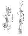
- the folding service line disclosed in Figures 1 and 2 includes an articulated boom assembly 10 having a plurality of boom sections 11 - 13 pivotally interconnected in and end-to-end manner.
- the inboard end of the inner boom section 11 is pivotally connected to a turret 17 for movement about a horizontal axis A.
- the turret 17 is rotatably mounted on a pedestal 18 for movement about a vertical axis B and the pedestal 18 is secured to a transportable chassis 19 for transportation to and from a work site.
- the inboard end of the intermediate boom section 12 is pivotally connected to the outboard end of the inner boom section 11 for pivotal movement about a horizontal axis C and the inboard end of the outer boom section 13 is connected to the boom section 12 for pivotal movement about a horizontal axis D.
- a support pod 24 and a foot 25 support the outer end of the inner boom 11 so the boom 10 can be unfolded into the work position shown in the dashed lines of Figure 1 with an outer support 29 resting on the ground G to support the outer end of the boom section 13.
- Each of the boom sections 11-13 comprises a pair of generally parallel boom members lla. llb; 12a. 12b: 13a, 13b (Fig. 2) pivotally interconnected by a pair of boom joints 30. 31 (Figs. 1 - 3).
- the boom joints (Fig. 3) each includes an inner cylindrical sleeve 35 having a pair of radially inward flanges 36. 37 at the end thereof and with the sleeve 35 of joint 31 (Figs. 2. 3) connected to the boom members 12a. 12b by a plurality of capscrews 40 each extending through a bore 41 in one of the boom members 12a. 12b into the threaded bore 42 in one of the flanges 36, 37.
- An outer cylindrical sleeve 46 of joint 31 is rotatably mounted around the inner sleeve 35 by a plurality of bearings 47 - 50 and the sleeve 46 is welded or otherwise connected to the outer boom members 13a, 13b.
- the boom joint 30 is similarly constructed to interconnect the boom sections 11, 12.
- the outer boom section 13 is moved from the folded position shown in the solid lines in Figure 1 into the extended position shown in the dashed lines of Figure 1 by power apparatus 57 comprising a hydraulic cylinder 58 pivotally connected to an ear 59 on the boom section 13 and having a cylinder rod 60 connected to a L-shaped lever 64 which in turn is pivotally connected to an ear 65 on the intermediate boom section 12.
- a lever arm 66 is pivotally connected between the boom sections 12, 13.
- Similar apparatus for folding an extending boom sections is shown in more detail in the embodiment of the invention shown in Figures 6, 7 and this apparatus will be described in more detail hereinafter.
- Another power apparatus 69 comprising a hydraulic cylinder 70 pivotally connected to an ear 71 on the inner boom section 11 and having a hydraulic rod 72 pivotally connected to an L-shaped lever 76 folds and extends the intermediate boom section 12 relative to the inner boom section 11.
- the L-shaped lever 76 is pivotally connected to an ear 77 on the intermediate boom 12 and the lever arm 78 is connected between the inner boom section 11 and the L-shaped lever 76.
- An articulated service line 82 (Figs. 1. 2) having a plurality of pipe sections 83 - 85 is supported by the boom assembly 11 and folds and extends along with the boom assembly.
- Each of the pipe sections 83 - 85 is mounted for support to a corresponding one of the boom sections 11 - 13 by one or more mounting brackets 86.
- the pipe sections 83 - 85 are connected by a plurality of pipe swivel joints 89, 90 and are connected to an input swivel joint 91 and to an output swivel joint 92.
- Each of the swivel joints 98 - 92 (Figs. 2, 3) includes an inner joint member 96 and an outer joint member 97 rotatably surrounding the inner joint member.
- Each of the pipe swivel joints 89, 90 is mounted inside a corresponding one of the boom joints 30, 31 with the pipe joint "floating" inside the corresponding boom joint to accommodate any expansion or contraction of the pipe sections relative to the boom sections.
- the outer pipe swivel joint 92 is similarly mounted in a boom joint 32 at an outboard end of the boom section 13.
- the inner and outer joints are each connected to at least one of the pipe sections 83 - 85 by one or more pipe elbows 98.
- a connector pipe 101 is connected to the outer pipe swivel joint 92 by a pipe elbow 98 and the inner pipe swivel joint 91 is connected to a vertical inlet pipe 102 (Figs. 1, 2) by another pipe elbow 98.
- FIG. 4 Another embodiment of the folding service line disclosed in Figures 4 and 5 includes an articulated boom assembly 110 having a plurality of boom sections 111 - 113 pivotally interconnected in an end-to-end manner.
- Each of the boom sections 111 - 113 includes a single boom member llla - 113a rather than the parallel pair of boom members disclosed in Figures 1 - 3.
- the inward end of the intermediate member 112a is fixed to a sheave 106 for pivotal movement about the horizontal axis C and the boom member l12a is raised and lowered by a pair of hydraulic cylinders 107, 108.
- the cylinders 107, 108 are mounted on the inner boom member llla and a hydraulic rod 117 of the cylinder 107 in connected to the sheave 106 by a cable 118.
- a cable 119 is connected between the sheave 106 and a hydraulic rod 123 of the cylinder 108. Contraction of the rod 117 into the cylinder 107 and extension of the rod 123 from the cylinder 108 causes the sheave 106 and the boom section 112 (Fig. 4) to rotate counterclockwise about the horizontal axis C.
- the inboard end of the outer boom member 113 is fixed to a cam 124 for pivotal movement of the outer boom member about the horizontal axis D.
- a cable 125 is connected between the cam 124 and the hydraulic cylinder 126.
- the cylinder 126 is pivotally connected to an ear 130 on the inner boom section 112.
- the cam 124 and the outer boom member 113 rotate counterclockwise from the solid line position in Figure 4 into a horizontal position shown in the dashed lines in Figure 4.
- the intermediate boom section 112 is rotated clockwise the boom is moved into the dashed line position shown in Figure 4 with the outer end of the boom section 111 supported above ground by a pod 131 and a foot 132.
- the outer end of the boom section 112 is supported by a pod 136 and a foot 137. and the outer end of the section 113 is supported by an outer support 129.
- the service line of figures 4 and 5 can be connected to a wellhead and operated with the outer support 129 at any one of a plurality of positions between the solid line position shown in Figure 4 and the dashed line position shown in Figure 4.
- the distance between the truck chassis 19 and the wellhead is not critical and the truck chassis 19 can be readily positioned in a working position adjacent a wellhead and the boom assembly extended to reach the wellhead.
- a third embodiment of the present invention disclosed in Figures 6 and 7 is similar to the embodiment disclosed in Figures 1 and 2 except the outer boom section 213 is folded into a position between the inner boom section 211 and the intermediate boom section 212 when the boom assembly 210 is in the stowed position shown in Figure 6.
- the power apparatus 57 is mounted on the underside of the extended boom section 212 (Fig. 7) as opposed to the mounting disclosed in the dashed lines of Figure 1.
- the power apparatus 69 for folding and extending the intermediate boom section 212 is mounted in the manner described in the embodiment of Figures 1 and 2.
- the rod 72 causes the L-shaped lever 76 to pivot about a horizontal axis E and causes the lever 78 to pivot about a horizontal axis F to extend the intermediate boom section 212 from the stowed position of Figure 6 toward the extended position of Figure 7.
- the outer ends of the boom sections 211. 212, 213 are each supported at the outer end by the pods 24, 142. 144 and the corresponding feet 25. 143 and 145.
- the present invention includes a folding boom assembly which supports an articulated well service pipeline having a plurality of long straight pipe sections interconnected by pipe elbows and swivel joints. Each of the pipe sections is supported by a corresponding boom section.
- the boom assembly and the service pipeline are folded onto a service vehicle for transportation and are extended for connection to a wellhead. Supports between the ground and the boom sections reduce the loads transmitted to the service vehicle so lighter boom assemblies can be used.
Landscapes
- Engineering & Computer Science (AREA)
- General Engineering & Computer Science (AREA)
- Geology (AREA)
- Life Sciences & Earth Sciences (AREA)
- Mining & Mineral Resources (AREA)
- Geochemistry & Mineralogy (AREA)
- Fluid Mechanics (AREA)
- General Life Sciences & Earth Sciences (AREA)
- Environmental & Geological Engineering (AREA)
- Physics & Mathematics (AREA)
- Mechanical Engineering (AREA)
- Supports For Pipes And Cables (AREA)
- Jib Cranes (AREA)
- Joints Allowing Movement (AREA)
- Aerials With Secondary Devices (AREA)
Applications Claiming Priority (2)
| Application Number | Priority Date | Filing Date | Title |
|---|---|---|---|
| US346448 | 1982-02-08 | ||
| US06/346,448 US4474213A (en) | 1982-02-08 | 1982-02-08 | Folding service line |
Publications (2)
| Publication Number | Publication Date |
|---|---|
| EP0086440A2 true EP0086440A2 (fr) | 1983-08-24 |
| EP0086440A3 EP0086440A3 (fr) | 1985-12-04 |
Family
ID=23359444
Family Applications (1)
| Application Number | Title | Priority Date | Filing Date |
|---|---|---|---|
| EP83101175A Withdrawn EP0086440A3 (fr) | 1982-02-08 | 1983-02-08 | Conduite de service repliable |
Country Status (6)
| Country | Link |
|---|---|
| US (1) | US4474213A (fr) |
| EP (1) | EP0086440A3 (fr) |
| JP (1) | JPS58176392A (fr) |
| BR (1) | BR8300597A (fr) |
| CA (1) | CA1200175A (fr) |
| MX (1) | MX154861A (fr) |
Cited By (3)
| Publication number | Priority date | Publication date | Assignee | Title |
|---|---|---|---|---|
| US5057309A (en) * | 1986-11-06 | 1991-10-15 | Hill Ira D | Oral hygiene preparations |
| US5057308A (en) * | 1986-11-06 | 1991-10-15 | Hill Ira D | Method of treating the oral cavity with oral hygiene preparations containing active SnF2 |
| US5098711A (en) * | 1988-11-14 | 1992-03-24 | Ira Hill | Method of treating the oral cavity with dental floss containing chemotherapeutic agents |
Families Citing this family (15)
| Publication number | Priority date | Publication date | Assignee | Title |
|---|---|---|---|---|
| US4898211A (en) * | 1988-11-21 | 1990-02-06 | Aeroquip Corporation | Counterbalanced refueling arm assembly |
| US5125857A (en) * | 1991-02-13 | 1992-06-30 | Nabors Industries, Inc. | Harness method for use in cold weather oil field operations and apparatus |
| US8590556B2 (en) * | 2011-03-07 | 2013-11-26 | Halliburton Energy Services, Inc. | Plug and pump system for routing pressurized fluid |
| MX355029B (es) * | 2012-05-25 | 2018-03-28 | Schlumberger Technology Bv | Transporte de líneas de servicio y sistema de despliegue. |
| US20140103698A1 (en) * | 2012-10-17 | 2014-04-17 | Bo Feng | Horizontally rotatable multi-knuckle boom |
| US9617796B2 (en) * | 2013-10-04 | 2017-04-11 | Electro Mechanical Industries, Inc. | Cable management system |
| US10190710B2 (en) | 2013-12-27 | 2019-01-29 | ClearCove Systems, Inc. | Foldable drain pipe for a decanter in a water treatment system |
| US9744482B2 (en) | 2013-12-27 | 2017-08-29 | ClearCove Systems, Inc. | Screen decanter for screening solids from waste water |
| US9782696B2 (en) | 2013-12-27 | 2017-10-10 | ClearCove Systems, Inc. | Method for maximizing uniform effluent flow through a waste water treatment system |
| US9643106B2 (en) | 2013-12-27 | 2017-05-09 | ClearCove Systems, Inc. | Screen decanter for removing solids from wastewater |
| US9855518B2 (en) | 2013-12-27 | 2018-01-02 | ClearCove Systems, Inc. | Method and apparatus for a vertical lift decanter system in a water treatment system |
| US9908067B2 (en) | 2013-12-27 | 2018-03-06 | ClearCove Systems, Inc. | Floatables and scum removal apparatus for a waste water treatment system |
| US10466719B2 (en) | 2018-03-28 | 2019-11-05 | Fhe Usa Llc | Articulated fluid delivery system with remote-controlled spatial positioning |
| CN214247295U (zh) * | 2020-11-17 | 2021-09-21 | 烟台杰瑞石油装备技术有限公司 | 用于压裂设备的软管快接装置 |
| US11557887B2 (en) * | 2020-12-08 | 2023-01-17 | Yantai Jereh Petroleum Equipment & Technologies Co., Ltd. | Cable laying device |
Family Cites Families (19)
| Publication number | Priority date | Publication date | Assignee | Title |
|---|---|---|---|---|
| US3053320A (en) * | 1960-03-28 | 1962-09-11 | Shell Oil Co | Fluid injection apparatus wells |
| US3217748A (en) * | 1963-06-26 | 1965-11-16 | John D Harper | Flexible insulated fluid transfer apparatus |
| US3281080A (en) * | 1963-11-14 | 1966-10-25 | J B Knight Co Inc | Irrigation system |
| US3399909A (en) * | 1966-02-17 | 1968-09-03 | Honeywell Inc | Transmitting apparatus |
| US3459222A (en) * | 1966-09-16 | 1969-08-05 | Philip W Mcelroy | Concrete conveying apparatus |
| US3498325A (en) * | 1967-09-14 | 1970-03-03 | Youngstown Sheet And Tube Co | Loading arm and quick release coupler |
| DE1923602A1 (de) * | 1969-05-08 | 1970-11-12 | Mcelroy Philip W | Betonfoerdervorrichtung |
| US3721260A (en) * | 1971-12-16 | 1973-03-20 | B Stahmer | Pleated extensible carriage for conveying flowable energy therealong |
| US3730228A (en) * | 1972-01-05 | 1973-05-01 | P Gibbs | Hose-case assembly |
| JPS5830465B2 (ja) * | 1973-07-28 | 1983-06-29 | キヨクトウカイハツコウギヨウ カブシキガイシヤ | 3 ダンイジヨウノクツセツシキブ−ムソウチ |
| US3942554A (en) * | 1974-04-19 | 1976-03-09 | Werner Corporation | Extendable crane with folding conduit |
| JPS5146729A (ja) * | 1974-10-18 | 1976-04-21 | Kyokuto Kaihatsu Kogyo Co | Konkuriitohonpu nyoru konkuriitosuiheidasetsusochi |
| US4050585A (en) * | 1975-11-07 | 1977-09-27 | Ameron, Inc. | Hydraulically balanced marine loading arm |
| GB1538867A (en) * | 1975-12-18 | 1979-01-24 | Nat Supply Co Ltd | Articulated arms |
| JPS5335525A (en) * | 1976-09-14 | 1978-04-03 | West Electric Co | Selffdeveloping film camera |
| US4130134A (en) * | 1976-12-13 | 1978-12-19 | Morgen Manufacturing Company | Material conveying apparatus |
| US4269239A (en) * | 1978-10-10 | 1981-05-26 | Fmc Corporation | Traveling loading arm for marine tankers |
| DE3013450A1 (de) * | 1980-04-05 | 1981-10-08 | Stetter Gmbh, 8940 Memmingen | Verteilermast einer betonpumpe |
| US4391297A (en) * | 1980-11-20 | 1983-07-05 | Fmc Corporation | Mono-rail boom supported articulated service line |
-
1982
- 1982-02-08 US US06/346,448 patent/US4474213A/en not_active Expired - Lifetime
-
1983
- 1983-02-04 MX MX196154A patent/MX154861A/es unknown
- 1983-02-07 BR BR8300597A patent/BR8300597A/pt unknown
- 1983-02-07 CA CA000421012A patent/CA1200175A/fr not_active Expired
- 1983-02-08 JP JP58020545A patent/JPS58176392A/ja active Pending
- 1983-02-08 EP EP83101175A patent/EP0086440A3/fr not_active Withdrawn
Cited By (3)
| Publication number | Priority date | Publication date | Assignee | Title |
|---|---|---|---|---|
| US5057309A (en) * | 1986-11-06 | 1991-10-15 | Hill Ira D | Oral hygiene preparations |
| US5057308A (en) * | 1986-11-06 | 1991-10-15 | Hill Ira D | Method of treating the oral cavity with oral hygiene preparations containing active SnF2 |
| US5098711A (en) * | 1988-11-14 | 1992-03-24 | Ira Hill | Method of treating the oral cavity with dental floss containing chemotherapeutic agents |
Also Published As
| Publication number | Publication date |
|---|---|
| US4474213A (en) | 1984-10-02 |
| BR8300597A (pt) | 1983-11-08 |
| CA1200175A (fr) | 1986-02-04 |
| JPS58176392A (ja) | 1983-10-15 |
| EP0086440A3 (fr) | 1985-12-04 |
| MX154861A (es) | 1987-12-22 |
Similar Documents
| Publication | Publication Date | Title |
|---|---|---|
| US4474213A (en) | Folding service line | |
| CA1203144A (fr) | Canalisations de service groupees sur fleche telescopique | |
| US8899268B2 (en) | Discharge arm assembly for pumping units | |
| US4391297A (en) | Mono-rail boom supported articulated service line | |
| CA2886153C (fr) | Dispositif de prise en charge d'un dispositif de bloc obturateur de puits | |
| US4828033A (en) | Apparatus and method for treatment of wells | |
| US4290495A (en) | Portable workover rig with extendable mast substructure, platform mounted drawworks and adjustable wellhead anchor | |
| US10302079B2 (en) | Methods and systems for routing pressurized fluid utilizing articulating arms | |
| RU2609041C1 (ru) | Манипулятор инжектора гибких труб | |
| CA2644271C (fr) | Systeme permettant d'effectuer des travaux au tube d'intervention et au tuyau raccorde | |
| US2993570A (en) | Portable trailer-mounted derrick | |
| CN112912587B (zh) | 管道处理器装置 | |
| US4468166A (en) | Apparatus for extending and retracting telescoping booms and pipelines | |
| US4457338A (en) | Telescoping boom supported flip-flop service line | |
| US4625760A (en) | Mobile concrete handling apparatus | |
| US2662797A (en) | Platform for portable drilling masts | |
| US9962630B2 (en) | Craneless MGS vessel and swivel joint U-tube mud line and method of installation | |
| EP0082377A1 (fr) | Soutien allongé pour structure télescopique | |
| EP0061070B1 (fr) | Flèche téléscopique de soutien pour un conduit de service basculant | |
| EP0060507A1 (fr) | Installation ajustable pour un conduit de service téléscopique | |
| US4420916A (en) | Method and apparatus for aligning and securing auxiliary equipment with respect to a well drilling platform | |
| SU1155204A1 (ru) | Устройство дл подсоединени дождевальных машин к гидрантам закрытой сети | |
| US20180051547A1 (en) | Transport and assembly rigging | |
| US20160168925A1 (en) | Method for installing an external line on a deployed drilling riser |
Legal Events
| Date | Code | Title | Description |
|---|---|---|---|
| PUAI | Public reference made under article 153(3) epc to a published international application that has entered the european phase |
Free format text: ORIGINAL CODE: 0009012 |
|
| AK | Designated contracting states |
Designated state(s): DE FR GB IT NL |
|
| 17P | Request for examination filed |
Effective date: 19840216 |
|
| PUAL | Search report despatched |
Free format text: ORIGINAL CODE: 0009013 |
|
| AK | Designated contracting states |
Designated state(s): DE FR GB IT NL |
|
| STAA | Information on the status of an ep patent application or granted ep patent |
Free format text: STATUS: THE APPLICATION HAS BEEN WITHDRAWN |
|
| 17Q | First examination report despatched |
Effective date: 19870202 |
|
| 18W | Application withdrawn |
Withdrawal date: 19870122 |
|
| RIN1 | Information on inventor provided before grant (corrected) |
Inventor name: JAMESON, NEAL E. |