EP0086461A1 - Procédé pour réduire le dépot de coke au cours du craquage catalytique et inhibiteur d'encrassement - Google Patents
Procédé pour réduire le dépot de coke au cours du craquage catalytique et inhibiteur d'encrassement Download PDFInfo
- Publication number
- EP0086461A1 EP0086461A1 EP83101277A EP83101277A EP0086461A1 EP 0086461 A1 EP0086461 A1 EP 0086461A1 EP 83101277 A EP83101277 A EP 83101277A EP 83101277 A EP83101277 A EP 83101277A EP 0086461 A1 EP0086461 A1 EP 0086461A1
- Authority
- EP
- European Patent Office
- Prior art keywords
- antifoulant
- antimony
- tin
- germanium
- metals
- Prior art date
- Legal status (The legal status is an assumption and is not a legal conclusion. Google has not performed a legal analysis and makes no representation as to the accuracy of the status listed.)
- Granted
Links
Images


Classifications
-
- C—CHEMISTRY; METALLURGY
- C10—PETROLEUM, GAS OR COKE INDUSTRIES; TECHNICAL GASES CONTAINING CARBON MONOXIDE; FUELS; LUBRICANTS; PEAT
- C10G—CRACKING HYDROCARBON OILS; PRODUCTION OF LIQUID HYDROCARBON MIXTURES, e.g. BY DESTRUCTIVE HYDROGENATION, OLIGOMERISATION, POLYMERISATION; RECOVERY OF HYDROCARBON OILS FROM OIL-SHALE, OIL-SAND, OR GASES; REFINING MIXTURES MAINLY CONSISTING OF HYDROCARBONS; REFORMING OF NAPHTHA; MINERAL WAXES
- C10G9/00—Thermal non-catalytic cracking, in the absence of hydrogen, of hydrocarbon oils
- C10G9/14—Thermal non-catalytic cracking, in the absence of hydrogen, of hydrocarbon oils in pipes or coils with or without auxiliary means, e.g. digesters, soaking drums, expansion means
- C10G9/16—Preventing or removing incrustation
-
- C—CHEMISTRY; METALLURGY
- C07—ORGANIC CHEMISTRY
- C07C—ACYCLIC OR CARBOCYCLIC COMPOUNDS
- C07C4/00—Preparation of hydrocarbons from hydrocarbons containing a larger number of carbon atoms
- C07C4/02—Preparation of hydrocarbons from hydrocarbons containing a larger number of carbon atoms by cracking a single hydrocarbon or a mixture of individually defined hydrocarbons or a normally gaseous hydrocarbon fraction
- C07C4/04—Thermal processes
-
- Y—GENERAL TAGGING OF NEW TECHNOLOGICAL DEVELOPMENTS; GENERAL TAGGING OF CROSS-SECTIONAL TECHNOLOGIES SPANNING OVER SEVERAL SECTIONS OF THE IPC; TECHNICAL SUBJECTS COVERED BY FORMER USPC CROSS-REFERENCE ART COLLECTIONS [XRACs] AND DIGESTS
- Y10—TECHNICAL SUBJECTS COVERED BY FORMER USPC
- Y10S—TECHNICAL SUBJECTS COVERED BY FORMER USPC CROSS-REFERENCE ART COLLECTIONS [XRACs] AND DIGESTS
- Y10S585/00—Chemistry of hydrocarbon compounds
- Y10S585/949—Miscellaneous considerations
- Y10S585/95—Prevention or removal of corrosion or solid deposits
Definitions
- This invention relates to processes for the thermal cracking of a gaseous stream containing hydrocarbons.
- this invention relates to a method for reducing the formation of carbon on the cracking tubes in furnaces used for the thermal cracking of a gaseous stream containing hydrocarbons and in any heat exchangers used to cool the effluent flowing from the furnaces.
- this invention relates to particular antifoulants which are useful for reducing the rate of formation of carbon on the walls of such cracking tubes and in such heat exchangers.
- the cracking furnace forms the heart of many chemical manufacturing processes. Often, the performance of the cracking furnace will carry the burden of the major profit potential of the entire manufacturing process. Thus, it is extremely desirable to maximize the performance of the cracking furnace.
- feed gas such as ethane and/or propane and/or naphtha is fed into the cracking furnace.
- a diluent fluid such as steam is usually combined with the feed material being provided to the cracking furnace.
- the feed stream which has been combined with the diluent fluid is converted to a gaseous mixture which primarily contains hydrogen, methane, ethylene, propylene, butadiene, and small amounts of heavier gases.
- this mixture is cooled, which allows removal of most of the heavier gases, and compressed.
- the compressed mixture is routed through various distillation columns where the individual components such as ethylene are purified and separated.
- the separated products of which ethylene is the major product, then leave the ethylene plant to be used in numerous other processes for the manufacture of a wide variety of secondary products.
- the primary function of the cracking furnace is to convert the feed stream to ethylene and/or propylene.
- a semi-pure carbon which is termed "coke” is formed in the cracking furnace as a result of the furnace cracking operation. Coke is also formed in the heat exchangers used to cool the gaseous_mixture flowing from the cracking furnace. Coke formation generally results from a combination of a homogeneous thermal reaction in the gas phase (thermal coking) and a heterogeneous catalytic reaction between the hydrocarbon in the gas phase and the metals in the walls of the cracking tubes or heat exchangers (catalytic coking).
- Coke is generally referred to as forming on the metal surfaces of the cracking tubes which are contacted with the feed stream and on the metal surfaces of the heat exchangers which are contacted with the gaseous effluent from the cracking furnace.
- coke may form on connecting conduits and other metal surfaces which are exposed to hydrocarbons at high temperatures.
- Metal will be used hereinafter to refer to all metal surfaces in a cracking process which are exposed to hydrocarbons and which are subject to coke deposition.
- a normal operating procedure for a cracking furnace is to periodically shut down the furnace in order to burn out the deposits of coke. This downtime results in a substantial loss of production.
- coke is an excellent thermal insulator.
- higher furnace temperatures are required to maintain the gas temperature in the cracking zone at a desired level. Such higher temperatures increase fuel consumption and will eventually result in shorter tube life.
- an antifoulant selected from the group consisting of tin, a combination of tin and antimony, a combination of germanium and antimony, a combination of tin and germanium and a combination of tin, antimony and germanium is contacted with the Metals either by pretreating the Metals with the antifoulant, adding the antifoulant to the hydrocarbon feedstock flowing to the cracking furnace or both.
- the use of the antifoulant substantially reduces the formation of coke on the Metals which substantially reduces the adverse consequences which attend such coke formation.
- the invention is described in terms of a cracking furnace used in a process for the manufacture of ethylene.
- the applicability of the invention described herein extends to other processes wherein a cracking furnace is utilized to crack a feed material into some desired components and the formation of coke on the walls of the cracking tubes in the cracking furnace or other metal surfaces associated with the cracking process is a problem.
- germanium Any suitable form of germanium may be utilized in the combination of germanium and antimony antifoulant, in the combination of tin and germanium antifoulant or in the combination of tin, antimony and germanium antifoulant. Elemental germanium, inorganic compounds and organic germanium compounds as well as mixtures of any two or more thereof are suitable sources of germanium. The term “germanium” generally refers to any one of these germanium sources.
- organic germanium compounds examples include compounds of the formula wherein R 1' R 2 , R 3 , and R 4 are selected independently from the group consisting of hydrogen, halogen, hydrocarbyl, and oxyhydrocarbyl.
- the hydrocarbyl and oxyhydrocarbyl radicals can have from 1-20 carbon atoms which may be substituted with halogen, nitrogen, phosphorus, or sulfur.
- Exemplary hydrocarbyl radicals are alkyl, alkenyl, cycloalkyl, aryl, and combinations thereof, such as alkylaryl or alkycycloalkyl.
- Germanium compounds such as tetrabutylgermanium, germanium tetraethoxide, tetraphenylgermanium, germanium tetraphenoxide, and diphenyldibromogermanium can be employed. At present germanium tetraethoxide is preferred.
- antimony Any suitable form of antimony may be utilized in the combination of tin and antimony antifoulant, in the combination of germanium and antimony antifoulant or in the combination of tin, antimony and germanium antifoulant. Elemental antimony, inorganic antimony compounds and organic antimony compounds as well as mixtures of any two or more thereof are suitable sources of antimony.
- the term "antimony” generally refers to any one of these antimony sources.
- organic antimony compounds which can be used include antimony carboxylates such as antimony triformate, antimony trioctoate, antimony triacetate, antimony tridodecanoate, antimony trioctadecanoate, antimony tribenzoate, and antimony tris(cyclohexenecarboxylate); antimony thiocarboxylates such as antimony tris(thioacetate), antimony tris(dithioacetate) and antimony tris(dithiopentanoate); antimony thiocarbonates such as antimony tris(0-propyl dithiocarbonate); antimony carbonates such as antimony tris(ethyl carbonates); trihydrocarbylantimony compounds such as triphenylantimony; trihydrocarbylantimony oxides such as triphenylantimony oxide; antimony salts of phenolic compounds such as antimony triphenoxide; antimony salts of thiophenolic compounds such as antimony tris(-thiophenoxide);
- tin antifoulant any suitable form of tin may be utilized as the tin antifoulant, in the combination of tin and antimony antifoulant, in the combination of tin and germanium antifoulant or in the-combination of tin, antimony and germanium antifoulant.
- Elemental tin, inorganic tin compounds, and organic tin compounds as well as mixtures of any two or more thereof are suitable sources of tin.
- the term "tin" generally refers to any one of these tin sources.
- examples of some inorganic tin compounds which can be used include tin oxides such as stannous oxide and stannic oxide; tin sulfides such as stannous sulfide and stannic sulfide; tin sulfates such as stannous sulfate and stannic sulfate; stannic acids such as metastannic acid and thiostannic acid; tin halides such as stannous fluoride, stannous chloride, stannous bromide, stannous iodide, stannic fluoride, stannic chloride, stannic bromide and stannic iodide; tin phosphates such as stannic phosphate; tin oxyhalides such as stannous oxychloride and stannic oxychloride; and the like. Of the inorganic tin compounds those which do not contain halogen are preferred as the source of tin.
- organic tin compounds which can be used include tin carboxylates such as stannous formate, stannous acetate, stannous butyrate, stannous octoate, stannous decanoate, stannous oxalate, stannous benzoate, and stannous cyclohexanecarboxylate; tin thiocarboxylates such as stannous thioacetate and stannous dithioacetate; dihydrocarbyltin bis(hydrocarbyl mercaptoalkanoates) such as dibutyltin bis(isooctyl mercaptoacetate) and dipropyltin bis(butyl mercaptoacetate); tin thiocarbonates such as stannous 0-ethyl dithiocarbonate; tin carbonates such as stannous propyl carbonate; tetrahydrocarbyltin compounds such as tetrabutyltin,
- any of the listed sources of tin may be combined with any of the listed sources of antimony or germanium to form the combination of tin and antimony antifoulant, the combination of tin and germanium antifoulant or the combination of tin, antimony and germanium antifoulant.
- any of the listed sources of germanium may be combined with any of the listed sources of antimony to form the combination of germanium and antimony antifoulant.
- any suitable concentration of antimony in the combination of tin and antimony antifoulant may be utilized.
- a concentration of antimony in the range of about 10 mole percent to about 75 mole percent is presently preferred because the effect of the combination of tin and antimony antifoulant is reduced outside of this range.
- any suitable concentration of antimony may be utilized in the combination of germanium and antimony antifoulant.
- a concentration of antimony in the range of about 10 mole percent to about 75 mole percent is presently preferred because the effect of the combination of germanium and antimony antifoulant is reduced outside of this range.
- germanium may be utilized in the combination of tin and germanium antifoulant.
- a concentration of germanium in the range of about 10 mole percent to about 75 mole percent is presently preferred because it is believed that the effect of the combination of tin and germanium antifoulant would be reduced outside this range.
- any suitable concentration of antimony in the combination of tin, antimony and germanium may be utilized.
- a concentration in the range of about 10 mole percent to about 65 mole percent is presently preferred.
- a concentration of germanium in the range of about 10 mole percent to about 65 mole percent is presently preferred.
- the combination antifoulants of the present invention are effective to reduce the buildup of coke on any of the high temperature steels.
- the tin antifoulant is considered to be effective to reduce the buildup of coke on any of the high temperature steels other than steels having an iron content of about 98 weight percent or higher.
- Commonly used steels in cracking tubes are Incoloy 800, Inconel 600, HK40, 11 ⁇ 4 chromium-1 ⁇ 2 molybdenum steel, and Type 304 Stainless Steel. The composition of these steels in weight percent is as follows:
- the antifoulants of the present invention may be contacted with the Metals either by pretreating the Metals with the antifoulant, adding the antifoulant to the hydrocarbon containing feedstock or preferably both.
- Suitable solvents include water, oxygen-containing organic liquids such as alcohols, ketones and esters and aliphatic and aromatic hydrocarbons and their derivatives.
- the presently preferred solvents are normal hexane and toluene although kerosene would be a typically used solvent in a commercial operation.
- any suitable concentration of the antifoulant in the solution may be utilized. It is desirable to use a concentration of at least 0.1 molar and concentrations may be 1 molar or higher with the strength of the concentrations being limited by metallurgical and economic considerations.
- the presently preferred concentration of antifoulant in the solution is in the range of about 0.2 molar to about 0.5 molar.
- Solutions of antifoulants can also be applied to the surfaces of the cracking tube by spraying or brushing when the surfaces are accessible but application in this manner has been found to provide less protection against coke deposition than immersion.
- the cracking tubes can also be treated with finely divided powders of the antifoulants but, again, this method is not considered to be particularly effective.
- any suitable concentration of the antifoulant may be added to the feed stream flowing through the cracking tube.
- a concentration of antifoulant in the feed stream of at least ten parts per million by weight of the metal(s) contained in the antifoulant based on the weight of the hydrocarbon portion of the feed stream should be used.
- Presently preferred concentrations of antifoulant metals in the feed stream are in the range of about 20 parts per million to about 100 parts per million based on the weight of the hydrocarbon portion of the feed stream. Higher concentrations of the antifoulant may be added to the feed stream but the effectiveness of the antifoulant does not substantially increase and economic considerations generally preclude the use of higher concentrations.
- Steam is generally utilized as a diluent for the hydrocarbon containing feedstock flowing to the cracking furnace.
- the steam/hydrocarbon molar ratio should not be allowed to exceed 2:1 when the tin antifoulant of the present invention is being used since the effectiveness of the tin antifoulant is substantially reduced at steam/hydrocarbon molar ratios above 2:1.
- the preferred steam/hydrocarbon molar ratio is in the range of about 0.25:1 to about 0.75:1 to enhance the effectiveness of the tin antifoulant.
- the steam/hydrocarbon molar ratio is considered to have very little effect on the use of the combination of tin and antimony antifoulant, the combination of germanium and antimony antifoulant, the combination of germanium and tin antifoulant or the combination of tin, antimony and germanium antifoulant. It is believed that the steam/hydrocarbon molar ratio is critical for tin alone because the tin antifoulant is volatile at high steam/hydrocarbon molar ratios. The combination antifoulants do not seem to exhibit this same volatility.
- the cracking furnace may be operated at any suitable temperature and pressure.
- the temperature of the fluid flowing through the cracking tubes increases during its transit through the tubes and will attain a maximum temperature at the exit of the cracking furnace of about 850°C.
- the wall temperature of the cracking tubes will be higher and may be substantially higher as an insulating layer of coke accumulates within the tubes.
- Furnace temperatures of nearly 2000°C may be employed.
- Typical pressures for a cracking operation will generally be in the range of about 10 to about 20 psig at the outlet of the cracking tube.
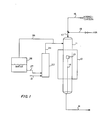
- FIGURE 1 Before referring specifically to the examples which will be utilized to further illustrate the present invention, the laboratory apparatus will be described by referring to FIGURE 1 in which a 9 millimeter quartz reactor 11 is illustrated. A part of the quartz reactor 11 is located inside the electric furnace 12. A metal coupon 13 is supported inside the reactor 11 on a two millimeter quartz rod 14 so as to provide only a minimal restriction to the flow of gases through the reactor 11. A hydrocarbon feed stream (ethylene) is provided to the reactor 11 through the combination of conduit means 16 and 17. Air is provided to the reactor 11 through the combination of conduit means 18 and 17.
- ethylene hydrocarbon feed stream
- Nitrogen flowing through conduit means 21 is passed through a heated saturator 22 and is provided through conduit means 24 to the reactor 11. Water is provided to the saturator 22 from the tank 26 through conduit means 27. Conduit means 28 is utilized for pressure equalization.
- Steam is generated by saturating the nitrogen carrier gas flowing through the saturator 22.
- the steam/nitrogen ratio is varied by adjusting the temperature of the electrically heated saturator 22.
- the selectivity of the converted ethylene to carbon monoxide was calculated according to equation 1 in which nitrogen was used as an internal standard.
- the conversion was calculated according to equation 2.
- the C0 level for the entire cycle was calculated as a weighted average of all the analyses taken during a cycle according to equation 3.
- the percent selectivity is directly related to the quantity of carbon monoxide in the effluent flowing from the reactor.
- Incoloy 800 coupons 1" x 1/4" x 1/16", were employed in this example. Prior to the application of a coating, each Incoloy 800 coupon was thoroughly cleaned with acetone. Each antifoulant was then applied by immersing the coupon in a minimum of 4mL of the antifoulant/solvent solution for 1 minute. A new coupon was used for each antifoulant. The coating was then followed by heat treatment in air at 700°C for 1 minute to decompose the antifoulant to its oxide and to remove any residual solvent. A blank coupon, used for comparisons, was prepared by washing the coupon in acetone and heat treating in air at 700°C for 1 minute without any coating. The preparation of the various coatings are given below.
- the temperature of the quartz reactor was maintained so that the hottest zone was 900 ⁇ 5°C.
- a coupon was placed in the reactor while the reactor was at reaction temperature.
- a typical run consisted of three 20 hour coking cycles (ethylene, nitrogen and steam), each of which was followed by a 5 minute nitrogen purge and a 50 minute decoking cycle (nitrogen, steam and air).
- ethylene, nitrogen and steam ethylene, nitrogen and steam
- a gas mixture consisting of 73mL per minute ethylene, 145mL per minute nitrogen and 73mL per minute steam passed downflow through the reactor.
- snap samples of the reactor effluent were analyzed in a gas chromatograph. The steam/hydrocarbon molar ratio was 1:1.
- Table I summarizes results of cyclic runs (with either 2 or 3 cycles) made with Incoloy 800 coupons that had been immersed in the test solutions A-H previously described.
- Runs 8 and 9 show an improvement over tin alone that is unexpected in view of the effect of germanium alone.
- the combination of tin and germanium antifoulant does not show the dramatic improvement exhibited by the combination of tin and antimony antifoulant and the combination of germanium and antimony antifoulant and thus this antifoulant is not the preferred antifoulant among the combination antifoulants.
- runs 8 and 9 are considered to be more exemplary of the effect of the combination of tin and germanium antifoulant and it is believed that this antifoulant is more effective than tin alone.
- Example 2 Using the process conditions of Example 1, a plurality of three cycle runs were made using antifoulants which contained different ratios of tin and antimony and different ratios of germanium and antimony. Each run employed a new Incoloy 800 coupon which had been cleaned and treated as described in Example 1. The antifoulant solutions were prepared as described in Example 1 with the exception that the ratio of the elements was varied. The results of these tests are illustrated in FIGURES 2 and 3.
- the combination of tin and antimony was particularly effective when the concentration of antimony ranged from about 10 mole percent to about 75 mole percent. Outside of this range, the effectiveness of the combination of tin and antimony was reduced particularly in the second and third cycles.
- the combination of germanium and antimony was effective when the concentration of antimony was in the range of about 10 mole percent to about 75 mole percent. Again, the effectiveness of the combination of germanium and antimony is reduced outside of this range. Also, it can be noted that the effectiveness of the combination of germanium and antimony is reduced more each cycle than was seen in the combination of tin and antimony.
- tin and germanium antifoulant would act essentially the same as the combination of tin and antimony antifoulant with respect to effectiveness as a function of concentration and thus a concentration of germanium in the combination of tin and germanium antifoulant is preferably in the range of about 10 mole percent to about 75 mole percent.
- Example 2 Coupons of 11 ⁇ 4 chromium-%molybdenum steel alloy, which is the alloy commonly used in transfer line heat exchangers in commercial ethylene cracking units, were cleaned in the manner described in Example 1. Separate coupons were then treated with solutions A, C or D of Example 1. Each coupon, including a control coupon, was then subjected to cyclic runs under the conditions set forth in Example 1. The results are summarized in Table II. Because of experimental difficulties associated with analysis of effluent gases, the reported observations are at different times but are nevertheless considered to provide a comparison of the effectiveness of the antifoulants.
- Example III Coupons of Type 304 Stainless Steel were cleaned in the manner described in Example 1. A coupon was then treated with solution C of Example 1. The treated coupon and a control coupon were then subjected to a cyclic run under the conditions set forth in Example 1. The results are summarized in Table III.
- the tin antifoulant of the present invention was used in tests on a commercial ethylene cracking furnace.
- the feedstock for the cracking furnace was ethane with the exception of a few relatively short intervals when propane was used.
- the cracking tubes were separated from the downstream transfer line heat exchanger and a solution containing stannous octoate was pumped into the cracking tubes to fill the tubes.
- the treating solution was prepared by diluting stannous octoate, catalyst T-9 from M & T Chemicals, Inc., with ten volumes of kerosene.
- the undiluted compound is reported by the manufacturer to contain typically 28 weight percent tin.
- the solution of stannous octoate was drained from the cracking tubes.
- the solution of stannous octoate was also applied by spraying to the transfer line heat exchanger.
- Operation of a cracking furnace is terminated when the inlet pressure to the cracking tubes exceeds a predetermined limit.
- the cracking furnace is shut down for oxidative burn-out to remove the coke obstruction.
- the tubes had operated without antifoulant from ten to thirty-one days and had been then subjected to an oxidative burn-out to remove coke.
- operation was maintained for 40, 49 and 47 days which is a substantial improvement over the 31-day maximum seen without the antifoulant treatment.
- Example 1 Using the procedure of Example 1 and solution C of Example 1, three separate runs were made at a steam/hydrocarbon molar ratio of 1:1, 2:1 and 2.5:1 respectively. The results of these tests are illustrated in FIGURE 4.
Landscapes
- Chemical & Material Sciences (AREA)
- Organic Chemistry (AREA)
- Oil, Petroleum & Natural Gas (AREA)
- Physics & Mathematics (AREA)
- Thermal Sciences (AREA)
- Engineering & Computer Science (AREA)
- Chemical Kinetics & Catalysis (AREA)
- General Chemical & Material Sciences (AREA)
- Production Of Liquid Hydrocarbon Mixture For Refining Petroleum (AREA)
- Cold Cathode And The Manufacture (AREA)
- Cell Electrode Carriers And Collectors (AREA)
Priority Applications (1)
| Application Number | Priority Date | Filing Date | Title |
|---|---|---|---|
| AT83101277T ATE19097T1 (de) | 1982-02-12 | 1983-02-10 | Prozess fuer die reduzierung der koksbildung in einem thermischen crackverfahren und zusammensetzung zur verhinderung von ablagerungen. |
Applications Claiming Priority (4)
| Application Number | Priority Date | Filing Date | Title |
|---|---|---|---|
| US34861482A | 1982-02-12 | 1982-02-12 | |
| US348614 | 1982-02-12 | ||
| US424889 | 1982-09-30 | ||
| US06/424,889 US4404087A (en) | 1982-02-12 | 1982-09-30 | Antifoulants for thermal cracking processes |
Publications (2)
| Publication Number | Publication Date |
|---|---|
| EP0086461A1 true EP0086461A1 (fr) | 1983-08-24 |
| EP0086461B1 EP0086461B1 (fr) | 1986-04-09 |
Family
ID=26995804
Family Applications (1)
| Application Number | Title | Priority Date | Filing Date |
|---|---|---|---|
| EP83101277A Expired EP0086461B1 (fr) | 1982-02-12 | 1983-02-10 | Procédé pour réduire le dépot de coke au cours du craquage catalytique et inhibiteur d'encrassement |
Country Status (7)
| Country | Link |
|---|---|
| US (1) | US4404087A (fr) |
| EP (1) | EP0086461B1 (fr) |
| CA (1) | CA1196030A (fr) |
| DE (1) | DE3362864D1 (fr) |
| ES (1) | ES8407109A1 (fr) |
| MX (1) | MX161243A (fr) |
| NO (1) | NO171923C (fr) |
Cited By (4)
| Publication number | Priority date | Publication date | Assignee | Title |
|---|---|---|---|---|
| EP0158968A3 (en) * | 1984-04-16 | 1986-09-10 | Phillips Petroleum Company | Antifoulants for thermal cracking processes |
| EP0241020A1 (fr) * | 1986-04-09 | 1987-10-14 | Phillips Petroleum Company | Agents prévenant l'encrassement dans des procédés de craquage thermique |
| EP0241845A1 (fr) * | 1986-04-09 | 1987-10-21 | Phillips Petroleum Company | Agents prévenant l'encrassement dans des procédés de craquage thermique |
| EP0242693A1 (fr) * | 1986-04-09 | 1987-10-28 | Phillips Petroleum Company | Agents prévenant l'encrassement dans des procédés de craquage thermique |
Families Citing this family (35)
| Publication number | Priority date | Publication date | Assignee | Title |
|---|---|---|---|---|
| US4507196A (en) * | 1983-08-16 | 1985-03-26 | Phillips Petroleum Co | Antifoulants for thermal cracking processes |
| US4863892A (en) * | 1983-08-16 | 1989-09-05 | Phillips Petroleum Company | Antifoulants comprising tin, antimony and aluminum for thermal cracking processes |
| US4724064A (en) * | 1983-11-17 | 1988-02-09 | Betz Laboratories, Inc. | Composition and method for coke retardant during hydrocarbon processing |
| US4545893A (en) * | 1984-07-20 | 1985-10-08 | Phillips Petroleum Company | Antifoulants for thermal cracking processes |
| JPS6162594A (ja) * | 1984-09-03 | 1986-03-31 | Giichi Ueki | 石油系燃料油の燃焼促進剤の製造法 |
| US4613372A (en) * | 1985-01-22 | 1986-09-23 | Phillips Petroleum | Antifoulants for thermal cracking processes |
| US4804487A (en) * | 1986-04-09 | 1989-02-14 | Phillips Petroleum Company | Antifoulants for thermal cracking processes |
| US5000836A (en) * | 1989-09-26 | 1991-03-19 | Betz Laboratories, Inc. | Method and composition for retarding coke formation during pyrolytic hydrocarbon processing |
| US5015358A (en) * | 1990-08-30 | 1991-05-14 | Phillips Petroleum Company | Antifoulants comprising titanium for thermal cracking processes |
| SA05260056B1 (ar) * | 1991-03-08 | 2008-03-26 | شيفرون فيليبس كيميكال كمبني ال بي | جهاز لمعالجة الهيدروكربون hydrocarbon |
| SA94150056B1 (ar) * | 1993-01-04 | 2005-10-15 | شيفرون ريسيرتش أند تكنولوجي كمبني | عمليات لإزالة الألكلة الهيدروجينية hydrodealkylation |
| CN1037765C (zh) * | 1993-01-04 | 1998-03-18 | 切夫里昂化学公司 | 脱氢方法 |
| US5405525A (en) * | 1993-01-04 | 1995-04-11 | Chevron Research And Technology Company | Treating and desulfiding sulfided steels in low-sulfur reforming processes |
| US5413700A (en) * | 1993-01-04 | 1995-05-09 | Chevron Research And Technology Company | Treating oxidized steels in low-sulfur reforming processes |
| USRE38532E1 (en) | 1993-01-04 | 2004-06-08 | Chevron Phillips Chemical Company Lp | Hydrodealkylation processes |
| US5284994A (en) * | 1993-01-13 | 1994-02-08 | Phillips Petroleum Company | Injection of antifoulants into thermal cracking reactors |
| US5575902A (en) * | 1994-01-04 | 1996-11-19 | Chevron Chemical Company | Cracking processes |
| US6274113B1 (en) | 1994-01-04 | 2001-08-14 | Chevron Phillips Chemical Company Lp | Increasing production in hydrocarbon conversion processes |
| US5658452A (en) * | 1994-01-04 | 1997-08-19 | Chevron Chemical Company | Increasing production in hydrocarbon conversion processes |
| US6258256B1 (en) | 1994-01-04 | 2001-07-10 | Chevron Phillips Chemical Company Lp | Cracking processes |
| US5516421A (en) * | 1994-08-17 | 1996-05-14 | Brown; Warren E. | Sulfur removal |
| US6464858B1 (en) | 1994-08-25 | 2002-10-15 | Phillips Petroleum Company | Method for improving the yield of heavy hydrocarbons in a thermal cracking process |
| CA2155044A1 (fr) * | 1994-08-25 | 1996-02-26 | Larry E. Reed | Methode pour faciliter l'ecaillage du coke resultant du craquage thermique des hydrocarbures |
| US5656150A (en) * | 1994-08-25 | 1997-08-12 | Phillips Petroleum Company | Method for treating the radiant tubes of a fired heater in a thermal cracking process |
| US6056870A (en) * | 1994-08-25 | 2000-05-02 | Reed; Larry E. | Method of promoting the decomposition of silicon compounds in a process for depositing silicon upon a metal surface |
| CA2196273C (fr) * | 1995-06-07 | 2004-11-30 | Daniel P. Hagewiesche | Utilisation de courants d'hydrocarbure pour la production d'une couche de protection metallique |
| US6497809B1 (en) * | 1995-10-25 | 2002-12-24 | Phillips Petroleum Company | Method for prolonging the effectiveness of a pyrolytic cracking tube treated for the inhibition of coke formation during cracking |
| US5853565A (en) * | 1996-04-01 | 1998-12-29 | Amoco Corporation | Controlling thermal coking |
| US5777188A (en) * | 1996-05-31 | 1998-07-07 | Phillips Petroleum Company | Thermal cracking process |
| US6419986B1 (en) | 1997-01-10 | 2002-07-16 | Chevron Phillips Chemical Company Ip | Method for removing reactive metal from a reactor system |
| WO2006125177A2 (fr) * | 2005-05-19 | 2006-11-23 | Massachusetts Institute Of Technology | Electrode et matieres catalytiques |
| US20090166259A1 (en) * | 2007-12-28 | 2009-07-02 | Steven Bradley | Metal-based coatings for inhibiting metal catalyzed coke formation in hydrocarbon conversion processes |
| US8057707B2 (en) * | 2008-03-17 | 2011-11-15 | Arkems Inc. | Compositions to mitigate coke formation in steam cracking of hydrocarbons |
| US8128887B2 (en) * | 2008-09-05 | 2012-03-06 | Uop Llc | Metal-based coatings for inhibiting metal catalyzed coke formation in hydrocarbon conversion processes |
| CN102260519B (zh) | 2010-05-31 | 2017-03-01 | 通用电气公司 | 烃类裂解方法和反应装置 |
Citations (3)
| Publication number | Priority date | Publication date | Assignee | Title |
|---|---|---|---|---|
| DE2026319B2 (de) * | 1970-05-29 | 1979-02-01 | Exxon Research And Engineering Co., Linden, N.J. (V.St.A.) | Verfahren zum thermischen Kracken einer Erdölfraktion |
| GB1602098A (en) * | 1978-05-25 | 1981-11-04 | Atomic Energy Authority Uk | Cracking of hydrocarbons |
| US4370220A (en) * | 1979-12-31 | 1983-01-25 | Exxon Research And Engineering Co. | Process for reducing coke formation in heavy feed catalytic cracking |
Family Cites Families (6)
| Publication number | Priority date | Publication date | Assignee | Title |
|---|---|---|---|---|
| US1847095A (en) * | 1927-03-11 | 1932-03-01 | Ig Farbenindustrie Ag | Prevention of the formation of carbon in operations carried out with hydrocarbons at an elevated temperature |
| US2063596A (en) * | 1932-02-19 | 1936-12-08 | Ig Farbenindustrie Ag | Thermal treatment of carbon compounds |
| US2901419A (en) * | 1954-02-18 | 1959-08-25 | Phillips Petroleum Co | Catalytic conversion with the addition of a metal or metallic compound |
| US3531394A (en) * | 1968-04-25 | 1970-09-29 | Exxon Research Engineering Co | Antifoulant additive for steam-cracking process |
| US3923921A (en) * | 1971-03-01 | 1975-12-02 | Exxon Research Engineering Co | Naphtha steam-cracking quench process |
| US4321129A (en) * | 1978-09-12 | 1982-03-23 | Phillips Petroleum Company | Cracking process employing catalyst having combination of antimony and tin |
-
1982
- 1982-09-30 US US06/424,889 patent/US4404087A/en not_active Expired - Lifetime
-
1983
- 1983-02-01 MX MX196104A patent/MX161243A/es unknown
- 1983-02-03 CA CA000420876A patent/CA1196030A/fr not_active Expired
- 1983-02-10 EP EP83101277A patent/EP0086461B1/fr not_active Expired
- 1983-02-10 DE DE8383101277T patent/DE3362864D1/de not_active Expired
- 1983-02-11 NO NO830457A patent/NO171923C/no not_active IP Right Cessation
- 1983-02-11 ES ES519750A patent/ES8407109A1/es not_active Expired
Patent Citations (3)
| Publication number | Priority date | Publication date | Assignee | Title |
|---|---|---|---|---|
| DE2026319B2 (de) * | 1970-05-29 | 1979-02-01 | Exxon Research And Engineering Co., Linden, N.J. (V.St.A.) | Verfahren zum thermischen Kracken einer Erdölfraktion |
| GB1602098A (en) * | 1978-05-25 | 1981-11-04 | Atomic Energy Authority Uk | Cracking of hydrocarbons |
| US4370220A (en) * | 1979-12-31 | 1983-01-25 | Exxon Research And Engineering Co. | Process for reducing coke formation in heavy feed catalytic cracking |
Cited By (4)
| Publication number | Priority date | Publication date | Assignee | Title |
|---|---|---|---|---|
| EP0158968A3 (en) * | 1984-04-16 | 1986-09-10 | Phillips Petroleum Company | Antifoulants for thermal cracking processes |
| EP0241020A1 (fr) * | 1986-04-09 | 1987-10-14 | Phillips Petroleum Company | Agents prévenant l'encrassement dans des procédés de craquage thermique |
| EP0241845A1 (fr) * | 1986-04-09 | 1987-10-21 | Phillips Petroleum Company | Agents prévenant l'encrassement dans des procédés de craquage thermique |
| EP0242693A1 (fr) * | 1986-04-09 | 1987-10-28 | Phillips Petroleum Company | Agents prévenant l'encrassement dans des procédés de craquage thermique |
Also Published As
| Publication number | Publication date |
|---|---|
| EP0086461B1 (fr) | 1986-04-09 |
| ES519750A0 (es) | 1984-08-16 |
| US4404087A (en) | 1983-09-13 |
| CA1196030A (fr) | 1985-10-29 |
| NO830457L (no) | 1983-08-15 |
| NO171923C (no) | 1993-05-19 |
| NO171923B (no) | 1993-02-08 |
| DE3362864D1 (en) | 1986-05-15 |
| ES8407109A1 (es) | 1984-08-16 |
| MX161243A (es) | 1990-08-24 |
Similar Documents
| Publication | Publication Date | Title |
|---|---|---|
| EP0086461B1 (fr) | Procédé pour réduire le dépot de coke au cours du craquage catalytique et inhibiteur d'encrassement | |
| EP0241020B1 (fr) | Agents prévenant l'encrassement dans des procédés de craquage thermique | |
| US4551227A (en) | Antifoulants for thermal cracking processes | |
| EP0134555B1 (fr) | Agents prévenant l'encrassement pour procédés de cracking thermique | |
| US5015358A (en) | Antifoulants comprising titanium for thermal cracking processes | |
| US4511405A (en) | Antifoulants for thermal cracking processes | |
| EP0189810B1 (fr) | Agents empêchant les encrassements pour procédés de craquage thermique | |
| EP0168824B1 (fr) | Préservatifs pour procédés de craquages thermiques | |
| EP0241845B1 (fr) | Agents prévenant l'encrassement dans des procédés de craquage thermique | |
| US4613372A (en) | Antifoulants for thermal cracking processes | |
| US4686201A (en) | Antifoulants comprising tin antimony and aluminum for thermal cracking processes | |
| US4863892A (en) | Antifoulants comprising tin, antimony and aluminum for thermal cracking processes | |
| EP0242693B1 (fr) | Agents prévenant l'encrassement dans des procédés de craquage thermique | |
| US4804487A (en) | Antifoulants for thermal cracking processes | |
| JPS6350399B2 (fr) |
Legal Events
| Date | Code | Title | Description |
|---|---|---|---|
| PUAI | Public reference made under article 153(3) epc to a published international application that has entered the european phase |
Free format text: ORIGINAL CODE: 0009012 |
|
| AK | Designated contracting states |
Designated state(s): AT BE CH DE FR GB IT LI LU NL SE |
|
| 17P | Request for examination filed |
Effective date: 19840127 |
|
| GRAA | (expected) grant |
Free format text: ORIGINAL CODE: 0009210 |
|
| AK | Designated contracting states |
Kind code of ref document: B1 Designated state(s): AT BE CH DE FR GB IT LI LU NL SE |
|
| REF | Corresponds to: |
Ref document number: 19097 Country of ref document: AT Date of ref document: 19860415 Kind code of ref document: T |
|
| ITF | It: translation for a ep patent filed | ||
| REF | Corresponds to: |
Ref document number: 3362864 Country of ref document: DE Date of ref document: 19860515 |
|
| ET | Fr: translation filed | ||
| PLBE | No opposition filed within time limit |
Free format text: ORIGINAL CODE: 0009261 |
|
| STAA | Information on the status of an ep patent application or granted ep patent |
Free format text: STATUS: NO OPPOSITION FILED WITHIN TIME LIMIT |
|
| 26N | No opposition filed | ||
| ITTA | It: last paid annual fee | ||
| EPTA | Lu: last paid annual fee | ||
| EAL | Se: european patent in force in sweden |
Ref document number: 83101277.8 |
|
| PGFP | Annual fee paid to national office [announced via postgrant information from national office to epo] |
Ref country code: NL Payment date: 20011214 Year of fee payment: 20 |
|
| PGFP | Annual fee paid to national office [announced via postgrant information from national office to epo] |
Ref country code: LU Payment date: 20011221 Year of fee payment: 20 |
|
| REG | Reference to a national code |
Ref country code: GB Ref legal event code: IF02 |
|
| PGFP | Annual fee paid to national office [announced via postgrant information from national office to epo] |
Ref country code: AT Payment date: 20020107 Year of fee payment: 20 |
|
| PGFP | Annual fee paid to national office [announced via postgrant information from national office to epo] |
Ref country code: GB Payment date: 20020108 Year of fee payment: 20 |
|
| PGFP | Annual fee paid to national office [announced via postgrant information from national office to epo] |
Ref country code: FR Payment date: 20020131 Year of fee payment: 20 |
|
| PGFP | Annual fee paid to national office [announced via postgrant information from national office to epo] |
Ref country code: SE Payment date: 20020201 Year of fee payment: 20 |
|
| PGFP | Annual fee paid to national office [announced via postgrant information from national office to epo] |
Ref country code: DE Payment date: 20020228 Year of fee payment: 20 |
|
| PGFP | Annual fee paid to national office [announced via postgrant information from national office to epo] |
Ref country code: BE Payment date: 20020318 Year of fee payment: 20 |
|
| PGFP | Annual fee paid to national office [announced via postgrant information from national office to epo] |
Ref country code: CH Payment date: 20020325 Year of fee payment: 20 |
|
| PG25 | Lapsed in a contracting state [announced via postgrant information from national office to epo] |
Ref country code: LI Free format text: LAPSE BECAUSE OF EXPIRATION OF PROTECTION Effective date: 20030209 Ref country code: GB Free format text: LAPSE BECAUSE OF EXPIRATION OF PROTECTION Effective date: 20030209 Ref country code: CH Free format text: LAPSE BECAUSE OF EXPIRATION OF PROTECTION Effective date: 20030209 |
|
| PG25 | Lapsed in a contracting state [announced via postgrant information from national office to epo] |
Ref country code: NL Free format text: LAPSE BECAUSE OF EXPIRATION OF PROTECTION Effective date: 20030210 Ref country code: LU Free format text: LAPSE BECAUSE OF EXPIRATION OF PROTECTION Effective date: 20030210 Ref country code: AT Free format text: LAPSE BECAUSE OF EXPIRATION OF PROTECTION Effective date: 20030210 |
|
| BE20 | Be: patent expired |
Owner name: *PHILLIPS PETROLEUM CY Effective date: 20030210 |
|
| REG | Reference to a national code |
Ref country code: GB Ref legal event code: PE20 Effective date: 20030209 |
|
| REG | Reference to a national code |
Ref country code: CH Ref legal event code: PL |
|
| EUG | Se: european patent has lapsed | ||
| NLV7 | Nl: ceased due to reaching the maximum lifetime of a patent |
Effective date: 20030210 |