EP0086524A2 - Pressrollen für Folienmaterial - Google Patents
Pressrollen für Folienmaterial Download PDFInfo
- Publication number
- EP0086524A2 EP0086524A2 EP83200172A EP83200172A EP0086524A2 EP 0086524 A2 EP0086524 A2 EP 0086524A2 EP 83200172 A EP83200172 A EP 83200172A EP 83200172 A EP83200172 A EP 83200172A EP 0086524 A2 EP0086524 A2 EP 0086524A2
- Authority
- EP
- European Patent Office
- Prior art keywords
- rolls
- skew
- plane
- tangency
- squeeze
- Prior art date
- Legal status (The legal status is an assumption and is not a legal conclusion. Google has not performed a legal analysis and makes no representation as to the accuracy of the status listed.)
- Withdrawn
Links
Images

Classifications
-
- B—PERFORMING OPERATIONS; TRANSPORTING
- B30—PRESSES
- B30B—PRESSES IN GENERAL
- B30B3/00—Presses characterised by the use of rotary pressing members, e.g. rollers, rings, discs
- B30B3/04—Presses characterised by the use of rotary pressing members, e.g. rollers, rings, discs co-operating with one another, e.g. with co-operating cones
Definitions
- the invention relates to improvements in squeeze rolls for sheet materials.
- rolls have been constructed with crowning which increases from the periphery to the centre in order to compensate the pressure reduction by means of a greater diameter.
- the invention proposes a mounting arrangement for the rolls which is able to completely and definitively solve this problem.
- this arrangement consists of making one roll assume a skew position relative to the other, i.e. one of the two rolls is rotated about an axis passing through the plane in which the axes of the rolls and their line of tangency originally lie, so that the rolls are no longer tangential along a straight line but at a point situated halfway along the length of the rolls, whereas the theoretical straight lines which previously mated to define the line of tangency now define a plane orthogonal to the axis about which one roll has been rotated.
- the angle of skew in reality is minimal, and in fact almost imperceptible to the eye, but is however such as to vary the degree of pressure from the centre to the periphery of the two rolls, with the consequent ability to obtain compensation of the squeezing pressure.
- the arrangement can be put into practice either with the machine at rest, by means of manual adjustment by releasing and moving the roll supports, or with the machine in motion, by means of a continuous movement using hydraulic units, operating screws with manual control, or an electric motor.
- squeeze rolls for sheet materials fed continuously between said rolls, wherein the rolls are kept tangential by forces applied to their ends, and wherein at least one of two adjacent rolls is rotated relative to the other about an axis orthogonal to the plane in which the two tangential rolls originally lie, and passing through the central section of the rolls; the original lines of tangency of the rolls now defining a plane orthogonal to said axis of rotation.
- the fabric unwinds from a reel and, suitably guided and deviated by rollers, is immersed in a tank containing the size or other solution with which it has to be impregnated, and takes it up.
- the fabric then passes through two rolls which, by squeezing the excess, cause this substance to penetrate further into the fabric. At the outlet, this latter is either collected on a beam, or passes directly to a drier or to a vaporisation chamber.
- the two aforesaid rolls are disposed according to the invention.
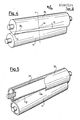
- the two rolls 10 and 11 are mutually skew such that their two straight lines 12 and 13, which in conventional equipment coincide to define the line of tangency, in this case are incident to each other and intersect at the point 14, which also constitutes the point of tangency of the two rolls 10 and 11.
- the rolls are rotated relative to each other about an axis x passing through said centre 14 and through the axes y and z of the two rolls, such that the two incident straight lines 12 and 13 lie in a plane p orthogonal to the axis x (Fig. 3).
- Figure 1 shows diagrammatically two devices for effecting said skew arrangement of the rolls.
- One of them consists of two screws 15 disposed at the opposite ends of one of the two rolls 10, and two nut screws l6 which are made to move along said screws by rotating these latter with handles 17.
- a mechanical transmission for example with bevel gears l8, enables the nut screws 16 to be moved simultaneously in the two opposite directions by rotating a single handle 17.
- One end of the roll 10 to be rotated is hinged to each nut screw l6, so as to obtain a manual degree of skew which is adjustable at will.
- a further method is to use two hydraulic cylinders 18 positioned in opposite directions, and having the ends of the roll to be rotated hinged to their rods 20.
- a suitable central hydraulic unit causes the cylinders to extend through the required stroke, thus controlling the required degree of skew of the rolls.
- Uniform pressure conditions between the rolls can always be obtained by adjusting the skew angle ⁇ at any given time, either manually or by other means, so producing an optimum degree of squeezing of the material advancing between them.
Landscapes
- Engineering & Computer Science (AREA)
- Mechanical Engineering (AREA)
- Treatment Of Fiber Materials (AREA)
- Folding Of Thin Sheet-Like Materials, Special Discharging Devices, And Others (AREA)
- Processing And Handling Of Plastics And Other Materials For Molding In General (AREA)
- Casting Or Compression Moulding Of Plastics Or The Like (AREA)
Applications Claiming Priority (2)
| Application Number | Priority Date | Filing Date | Title |
|---|---|---|---|
| IT67170/82A IT1155609B (it) | 1982-02-15 | 1982-02-15 | Perfezionamenti a cilindri spremitori di materiale in fogli |
| IT6717082 | 1982-02-15 |
Publications (2)
| Publication Number | Publication Date |
|---|---|
| EP0086524A2 true EP0086524A2 (de) | 1983-08-24 |
| EP0086524A3 EP0086524A3 (de) | 1985-05-15 |
Family
ID=11300173
Family Applications (1)
| Application Number | Title | Priority Date | Filing Date |
|---|---|---|---|
| EP83200172A Withdrawn EP0086524A3 (de) | 1982-02-15 | 1983-02-01 | Pressrollen für Folienmaterial |
Country Status (2)
| Country | Link |
|---|---|
| EP (1) | EP0086524A3 (de) |
| IT (1) | IT1155609B (de) |
Cited By (2)
| Publication number | Priority date | Publication date | Assignee | Title |
|---|---|---|---|---|
| US6676582B1 (en) * | 2000-01-07 | 2004-01-13 | Ashbrook Corporation | Belt pressure roller |
| EP1520475A1 (de) * | 2003-10-01 | 2005-04-06 | Doge Food Processing Machinery S.r.l. | Vorrichtung zum Auswalzen eines Teigblattes |
Family Cites Families (5)
| Publication number | Priority date | Publication date | Assignee | Title |
|---|---|---|---|---|
| US2762295A (en) * | 1950-11-01 | 1956-09-11 | Carding Spec Canada | Distribution of pressure between a pair of pressure rollers |
| DE1218703B (de) * | 1963-05-07 | 1966-06-08 | Demag Ag | Mehrwalzenkalander |
| US3545827A (en) * | 1968-06-25 | 1970-12-08 | Fmc Corp | Roller position adjustment mechanism |
| DE2042452C3 (de) * | 1970-08-27 | 1975-01-16 | Neumuenstersche Maschinen- Und Apparatebau Gmbh, 2350 Neumuenster | Vorrichtung zum Auftragen von Flüssigkeiten auf Folien |
| US4348952A (en) * | 1981-01-19 | 1982-09-14 | Usm Corporation | Cross axis mechanism |
-
1982
- 1982-02-15 IT IT67170/82A patent/IT1155609B/it active
-
1983
- 1983-02-01 EP EP83200172A patent/EP0086524A3/de not_active Withdrawn
Cited By (2)
| Publication number | Priority date | Publication date | Assignee | Title |
|---|---|---|---|---|
| US6676582B1 (en) * | 2000-01-07 | 2004-01-13 | Ashbrook Corporation | Belt pressure roller |
| EP1520475A1 (de) * | 2003-10-01 | 2005-04-06 | Doge Food Processing Machinery S.r.l. | Vorrichtung zum Auswalzen eines Teigblattes |
Also Published As
| Publication number | Publication date |
|---|---|
| EP0086524A3 (de) | 1985-05-15 |
| IT8267170A0 (it) | 1982-02-15 |
| IT8267170A1 (it) | 1983-08-15 |
| IT1155609B (it) | 1987-01-28 |
Similar Documents
| Publication | Publication Date | Title |
|---|---|---|
| EP0582678B1 (de) | Breitdehnvorrichtung | |
| DE644905C (de) | Verfahren und Vorrichtung zum Schrumpfen von Waeschestoffen | |
| DE69115339T2 (de) | Beschichtungsvorrichtung zum Beschichten von Leimpresswalzen, Papier oder Karton | |
| DE68901850T2 (de) | Zur schleifbearbeitung von zylindrischen lagerflaechen von werkstuecken, insbesondere fuer die bearbeitung von kurbelwellen- und kurbelzapfen mittels bandschleifer. | |
| DE60001389T2 (de) | Transferdruckmaschine | |
| EP3119583A1 (de) | Winkelverstellbare anpress- oder nipwalze | |
| DE4103342C1 (de) | ||
| DE2939797A1 (de) | Verfahren zum kontinuierlichen beschaeumen eines textilen flaechengebildes und vorrichtung zum durchfuehren des verfahrens | |
| US3881445A (en) | Apparatus for sequentially evacuating and impregnating a textile web | |
| EP0959032B1 (de) | Verfahren und Wickelmaschine zum Aufwickeln einer Materialbahn | |
| EP0086524A2 (de) | Pressrollen für Folienmaterial | |
| EP0295354B1 (de) | Verfahren zum Glätten und Schrumpfen von textiler Schlauchware | |
| DE19714645A1 (de) | Walze für eine Vorrichtung zum Beschichten einer Materialbahn, insbesondere einer Papier- oder Kartonbahn | |
| DD284711A5 (de) | Kontinuierliches dekatierverfahren eines gewebes und einrichtung dazu | |
| DE1111932B (de) | Walze fuer die Druckbehandlung von Waren-bahnen, insbesondere aus Papier | |
| EP0534930B1 (de) | Vorrichtung und Anordnung zum Bearbeiten von bahnförmigem Material | |
| EP0613737B1 (de) | Walzenanordnung mit einer Durchbiegungsausgleichswalze | |
| EP0745724B1 (de) | Walzenpresse | |
| EP0149108B1 (de) | Walzvorrichtung | |
| EP0649926B1 (de) | Vorrichtung zum kontinuierlichen Pressen, Dekatieren und Fixieren von bahnförmigem Textilgut wie Gewebe, Gewirke oder dergleichen | |
| DE4445478A1 (de) | Schlichtvorrichtung | |
| EP0286767B1 (de) | Verfahren und Vorrichtung zum kontinuierlichen Aufbringen von Flotte auf eine saugfähige, kompressible Materialbahn | |
| CH337723A (de) | Einrichtung zum Behandeln einer feuchten Papierbahn | |
| WO1990007417A1 (de) | Prägekalander | |
| DE2822962A1 (de) | Verfahren und vorrichtung zum glaetten von auf einen traeger aufgetragener ueberzugsmasse |
Legal Events
| Date | Code | Title | Description |
|---|---|---|---|
| PUAI | Public reference made under article 153(3) epc to a published international application that has entered the european phase |
Free format text: ORIGINAL CODE: 0009012 |
|
| AK | Designated contracting states |
Designated state(s): AT BE CH DE FR GB LI LU NL SE |
|
| PUAL | Search report despatched |
Free format text: ORIGINAL CODE: 0009013 |
|
| AK | Designated contracting states |
Designated state(s): AT BE CH DE FR GB LI LU NL SE |
|
| STAA | Information on the status of an ep patent application or granted ep patent |
Free format text: STATUS: THE APPLICATION IS DEEMED TO BE WITHDRAWN |
|
| 18D | Application deemed to be withdrawn |
Effective date: 19850829 |