EP0086558A1 - Réseau d'antennes - Google Patents
Réseau d'antennes Download PDFInfo
- Publication number
- EP0086558A1 EP0086558A1 EP83300199A EP83300199A EP0086558A1 EP 0086558 A1 EP0086558 A1 EP 0086558A1 EP 83300199 A EP83300199 A EP 83300199A EP 83300199 A EP83300199 A EP 83300199A EP 0086558 A1 EP0086558 A1 EP 0086558A1
- Authority
- EP
- European Patent Office
- Prior art keywords
- array
- feed connection
- circuit
- signal
- feed
- Prior art date
- Legal status (The legal status is an assumption and is not a legal conclusion. Google has not performed a legal analysis and makes no representation as to the accuracy of the status listed.)
- Withdrawn
Links
- 230000005855 radiation Effects 0.000 claims abstract description 12
- 230000002238 attenuated effect Effects 0.000 claims abstract description 9
- 230000000694 effects Effects 0.000 claims description 5
- 238000003491 array Methods 0.000 abstract description 5
- 238000013459 approach Methods 0.000 abstract 1
- 238000010586 diagram Methods 0.000 description 5
- 230000000717 retained effect Effects 0.000 description 2
- 230000009286 beneficial effect Effects 0.000 description 1
- 230000008030 elimination Effects 0.000 description 1
- 238000003379 elimination reaction Methods 0.000 description 1
- 230000001629 suppression Effects 0.000 description 1
Images

Classifications
-
- H—ELECTRICITY
- H01—ELECTRIC ELEMENTS
- H01Q—ANTENNAS, i.e. RADIO AERIALS
- H01Q25/00—Antennas or antenna systems providing at least two radiating patterns
- H01Q25/005—Antennas or antenna systems providing at least two radiating patterns providing two patterns of opposite direction; back to back antennas
-
- H—ELECTRICITY
- H01—ELECTRIC ELEMENTS
- H01Q—ANTENNAS, i.e. RADIO AERIALS
- H01Q11/00—Electrically-long antennas having dimensions more than twice the shortest operating wavelength and consisting of conductive active radiating elements
- H01Q11/02—Non-resonant antennas, e.g. travelling-wave antenna
-
- H—ELECTRICITY
- H01—ELECTRIC ELEMENTS
- H01Q—ANTENNAS, i.e. RADIO AERIALS
- H01Q21/00—Antenna arrays or systems
- H01Q21/29—Combinations of different interacting antenna units for giving a desired directional characteristic
-
- H—ELECTRICITY
- H01—ELECTRIC ELEMENTS
- H01Q—ANTENNAS, i.e. RADIO AERIALS
- H01Q3/00—Arrangements for changing or varying the orientation or the shape of the directional pattern of the waves radiated from an antenna or antenna system
- H01Q3/26—Arrangements for changing or varying the orientation or the shape of the directional pattern of the waves radiated from an antenna or antenna system varying the relative phase or relative amplitude of energisation between two or more active radiating elements; varying the distribution of energy across a radiating aperture
Definitions
- This invention relates to antenna array circuits, in particular for travelling-wave arrays, and is concerned with the elimination or reduction of unwanted sidelobes in the radiation patterns of such arrays.
- the radiation pattern of a first antenna has a sidelobe which is required to be reduced
- the present invention enables a smimilar affect to be obtained using only a single antenna array and is therefore more economical in this respect.
- the present invention is applicable only to travelling-wave arrays operating with main beams pointing off normal to the array, and can produce complete or partial cancellation of a sidelobe symmetrically placed about the normal from the main beam. This is particularly useful when operating with the main beam close to 90° off the normal (ie approaching end-fire) and suppression of a symmetrically occurring back lobe is required.
- the array itself should have a high degree of symmetry, in the sense that the radiation patterns when the array is fed from two alternative terminals thereof (usually but not essentially at respective ends of the array, as hereinafter explained) are mirror-images of one another. To the extent that the array lacks such symmetry, the beneficial effect of the present invention may be reduced.
- a symmetrical array will be physically symmetrical about the mid-point of the array, in the sense that its configuration relative to an observer will be unchanged if it is rotated through 180° in the plane of the array about an axis through the mid-point and perpendicular to that plane).
- the invention has one application in microstrip antennas, but is not limited thereto and can be applied to any form of travelling-wave array, eg waveguide slots, dipole arrays or triplate slots.
- an antenna array circuit comprises:
- the coaction of the two signals may be performed either at the radio-frequency of the array, or at baseband (eg video) frequency.
- the invention can provide either a receiving or a transmitting array circuit.
- the second feed connection may include an attenuator, means being provided for subtracting the attenuated signal in the second feed connection from the signal in the first feed connection to provide a receiver signal in which the unwanted sidelobe is reduced or eliminated; one feed connection (preferably said second) . may include phase-reversal means, the aforesaid subtraction being obtained by adding the phase-reversed signal in said one feed connection to the signal in the other connection.
- the second feed connection comprises mismatch means for reflecting the travelling wave from the array back into the array with the appropriate phase and amplitude to reduce or eliminate the unwanted sidelobe.
- the invention provides only a receiving array circuit.
- the first and second feed connections may both include undirectional conducting means for deriving the baseband frequency from the radio-frequency signals in the array, the second feed connection a3.so including attenuator means and means being provided for subtracting the thus-attenuated baseband signal in the second feed connection from the baseband signal in the first feed connection to provide the receiver signal.
- a symmetrical travelling-wave array is shown symbolically as a rectangle 1.
- the travelling wave travels in the direction of arrow 3 and the radiation pattern comprises a main beam 4 and a sidelobe 5.
- the radiation patterns are seen to be mirror-images of each other, either side of a transverse plane normal to the plane of the array, and in this example each sidelobe is symmetrically placed about the normal from its respective main beam.
- the wanted main beam is beam 4, and that it is desired to eliminate, or at least substantially reduce, the unwanted sidelobe 5. (If 4' were the wanted main beam and 5' the unwanted sidelobe, the array connections to be described would be reversed.)
- connection 2 is taken direct to a radio-frequency adder 6.
- the connection 2' is taken to adder 6 via a variable phase-shifter 7 and a variable attenuator 8.
- the two latter components are adjusted so that the amplitude of the main beam 4' matches that of sidelobe 5 and the phase of main beam 4' is opposite to that of sidelobe 5, as nearly as possible, ie phase-shifter 7 is adjusted to effect phase reversal. In this way the attenuated main beam 4' is effectively subtracted from the sidelobe 5 at adder 6, to reduce or eliminate it.
- a receiver is connected to connection 9.
- the impedances of connections 2 and 2' must match the array impedance to prevent reflections.
- phase-shifter 7 and the attenuator 8 can each be connected in a different feed connection 2,2', but it is preferred to connect them in the same connection as shown, in order to maximise the net receiver signal.
- adder 6 In transmitting form phase-shifter 7 is retained but attenuator 8 is omitted, and adder 6 is replaced by a coupler which couples-off the appropriate fraction of the transmitter output (connected to connection 9) to match the amplitude of the unwanted sidelobe.
- connection 2' is taken to a mismatch unit 10 which reflects the travelling wave back into the array (see arrow 3") with the appropriate amplitude and with phase-reversal so that the attenuated beam 4 1 is effectively subtracted in the array itself and eliminates or reduces sidelobe 5'.
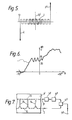
- Fig 5 shows, to scale, a symmetrical, tapered- aperture, microstrip array. Its symmetry can be seen by notionally rotating it about the intersection of its longitudinal and transverse axes, 11 and 12 respectively, when its configuration remains unchanged.
- the array is designed for operation at about 17 GHz, the lengths of the transverse sections being 0.75 ⁇ g and of the longitudinal sections 0.25 ⁇ g where ⁇ g is the wavelength in the strip at 17GHz.
- Figs 1-5 the two feed connections are talcen from terminals at physically opposite ends of the array, but this is not essential provid.ed an electrically equivalent result is obtained.
- British Patent Specification No 1,503,664 there is described with reference to Fig 3 thereof an array of triplate slots having two stripline feeders, arranged as in the array 1' of present Fig 7. (Usually, of course, the radiators of a travelling-wave array are spaced along a single feeder.)
- Feeder 13 of array 1' is straight, whereas feeder 15 has a sinuous configuration which effectively increases its length between slots 14 so as to effectively reduce the wavelength of the conveyed microwave energy.
- the connections to the respective feeder terminals are made at the same end of the row of slots 14.
- Fig 7 is a circuit diagram corresponding to Fig 2 for an embodiment of the present invention using an array 1' of this kind, both feed connections 2,2 t being made to the same end of the array(only part of which is shown).
- the array 1' can similarly be used in embodiments corresponding to Figs 3 and 4.
Landscapes
- Variable-Direction Aerials And Aerial Arrays (AREA)
Applications Claiming Priority (2)
| Application Number | Priority Date | Filing Date | Title |
|---|---|---|---|
| GB8203580 | 1982-02-08 | ||
| GB8203580 | 1982-02-08 |
Publications (1)
| Publication Number | Publication Date |
|---|---|
| EP0086558A1 true EP0086558A1 (fr) | 1983-08-24 |
Family
ID=10528176
Family Applications (1)
| Application Number | Title | Priority Date | Filing Date |
|---|---|---|---|
| EP83300199A Withdrawn EP0086558A1 (fr) | 1982-02-08 | 1983-01-14 | Réseau d'antennes |
Country Status (2)
| Country | Link |
|---|---|
| US (1) | US4529988A (fr) |
| EP (1) | EP0086558A1 (fr) |
Cited By (4)
| Publication number | Priority date | Publication date | Assignee | Title |
|---|---|---|---|---|
| DE3711184A1 (de) * | 1987-04-02 | 1988-10-20 | Leybold Ag | Vorrichtung zur einbringung von mikrowellenenergie mit einem offenen mikrowellenleiter |
| FR2703837A1 (fr) * | 1993-04-06 | 1994-10-14 | Kikuchi Hiroshi | Antenne à onde progressive à amplification paramétrique. |
| US7639191B2 (en) | 2005-07-04 | 2009-12-29 | Telefonaktiebolaget L M Ericsson (Publ) | Multi beam repeater antenna for increased coverage |
| EP1900063A4 (fr) * | 2005-07-04 | 2014-04-09 | Ericsson Telefon Ab L M | Antenne améliorée de répéteur à utiliser dans des applications point à point |
Families Citing this family (5)
| Publication number | Priority date | Publication date | Assignee | Title |
|---|---|---|---|---|
| US4958166A (en) * | 1988-08-22 | 1990-09-18 | General Dynamics Corp., Pomona Division | Amplitude monopulse slotted array |
| FI114756B (fi) * | 2003-02-14 | 2004-12-15 | Vaisala Oyj | Menetelmä ja laite kulkuaaltoantennin tehonjaon ohjaamiseksi |
| US8854212B2 (en) * | 2009-03-30 | 2014-10-07 | Datalogic Automation, Inc. | Radio frequency identification tag identification system |
| US9484978B2 (en) * | 2015-03-25 | 2016-11-01 | Htc Corporation | System and method for communication with adjustable signal phase and power |
| CN111366918A (zh) * | 2020-02-13 | 2020-07-03 | 中国电子科技集团公司第二十九研究所 | 一种切旁瓣方法及装置 |
Citations (4)
| Publication number | Priority date | Publication date | Assignee | Title |
|---|---|---|---|---|
| DE710453C (de) * | 1940-05-01 | 1941-09-13 | Telefunken Gmbh | Anordnung zur Unterdrueckung der rueckseitigen Strahlung einer Rhombusantenne |
| DE738032C (de) * | 1937-05-05 | 1943-07-31 | Telefunken Gmbh | Antenne mit fortschreitenden Wellen |
| GB1503664A (en) * | 1975-05-09 | 1978-03-15 | Decca Ltd | Microwave antenna |
| US4196436A (en) * | 1978-11-14 | 1980-04-01 | Ford Motor Company | Differential backlobe antenna array |
Family Cites Families (3)
| Publication number | Priority date | Publication date | Assignee | Title |
|---|---|---|---|---|
| US1768239A (en) * | 1925-07-08 | 1930-06-24 | Western Electric Co | Directive antenna system |
| DE1111251B (de) * | 1958-12-31 | 1961-07-20 | Rundfunk Betr Stechnik G M B H | Antennenanordnung zum Empfang vertikal polarisierter elektrischer Wellen |
| DE1093433B (de) * | 1959-07-21 | 1960-11-24 | Telefunken Gmbh | Empfangsanlage mit einer Rhombusantenne od. dgl. |
-
1983
- 1983-01-14 EP EP83300199A patent/EP0086558A1/fr not_active Withdrawn
- 1983-02-07 US US06/464,135 patent/US4529988A/en not_active Expired - Fee Related
Patent Citations (4)
| Publication number | Priority date | Publication date | Assignee | Title |
|---|---|---|---|---|
| DE738032C (de) * | 1937-05-05 | 1943-07-31 | Telefunken Gmbh | Antenne mit fortschreitenden Wellen |
| DE710453C (de) * | 1940-05-01 | 1941-09-13 | Telefunken Gmbh | Anordnung zur Unterdrueckung der rueckseitigen Strahlung einer Rhombusantenne |
| GB1503664A (en) * | 1975-05-09 | 1978-03-15 | Decca Ltd | Microwave antenna |
| US4196436A (en) * | 1978-11-14 | 1980-04-01 | Ford Motor Company | Differential backlobe antenna array |
Cited By (4)
| Publication number | Priority date | Publication date | Assignee | Title |
|---|---|---|---|---|
| DE3711184A1 (de) * | 1987-04-02 | 1988-10-20 | Leybold Ag | Vorrichtung zur einbringung von mikrowellenenergie mit einem offenen mikrowellenleiter |
| FR2703837A1 (fr) * | 1993-04-06 | 1994-10-14 | Kikuchi Hiroshi | Antenne à onde progressive à amplification paramétrique. |
| US7639191B2 (en) | 2005-07-04 | 2009-12-29 | Telefonaktiebolaget L M Ericsson (Publ) | Multi beam repeater antenna for increased coverage |
| EP1900063A4 (fr) * | 2005-07-04 | 2014-04-09 | Ericsson Telefon Ab L M | Antenne améliorée de répéteur à utiliser dans des applications point à point |
Also Published As
| Publication number | Publication date |
|---|---|
| US4529988A (en) | 1985-07-16 |
Similar Documents
| Publication | Publication Date | Title |
|---|---|---|
| US4804965A (en) | Flat wide-band antenna | |
| US4689627A (en) | Dual band phased antenna array using wideband element with diplexer | |
| US5451969A (en) | Dual polarized dual band antenna | |
| US3887925A (en) | Linearly polarized phased antenna array | |
| US5428364A (en) | Wide band dipole radiating element with a slot line feed having a Klopfenstein impedance taper | |
| US3854140A (en) | Circularly polarized phased antenna array | |
| US4044360A (en) | Two-mode RF phase shifter particularly for phase scanner array | |
| JP4021150B2 (ja) | スロットアレーアンテナ | |
| EP0457500B1 (fr) | Antenne à polarisation double linéaire et double circulaire | |
| US4500887A (en) | Microstrip notch antenna | |
| US3713167A (en) | Omni-steerable cardioid antenna | |
| US20020018024A1 (en) | Source-antennas for transmitting/receiving electromagnetic waves | |
| EP0203777B1 (fr) | Amplificateur spatial | |
| US4641144A (en) | Broad beamwidth lens feed | |
| US4721960A (en) | Beam forming antenna system | |
| EP0700115B1 (fr) | Antenne microbandes | |
| JPH08181537A (ja) | マイクロ波アンテナ | |
| US4260988A (en) | Stripline antenna for microwaves | |
| US4713670A (en) | Planar microwave antenna having high antenna gain | |
| US3569870A (en) | Feed system | |
| US3916349A (en) | Phase shifter for linearly polarized antenna array | |
| US4418429A (en) | Mixer for use in a microwave system | |
| US4529988A (en) | Travelling wave antenna with side lobe elimination | |
| US4063248A (en) | Multiple polarization antenna element | |
| US3560976A (en) | Feed system |
Legal Events
| Date | Code | Title | Description |
|---|---|---|---|
| PUAI | Public reference made under article 153(3) epc to a published international application that has entered the european phase |
Free format text: ORIGINAL CODE: 0009012 |
|
| AK | Designated contracting states |
Designated state(s): DE FR GB |
|
| 17P | Request for examination filed |
Effective date: 19840120 |
|
| 17Q | First examination report despatched |
Effective date: 19860121 |
|
| STAA | Information on the status of an ep patent application or granted ep patent |
Free format text: STATUS: THE APPLICATION IS DEEMED TO BE WITHDRAWN |
|
| 18D | Application deemed to be withdrawn |
Effective date: 19860603 |
|
| RIN1 | Information on inventor provided before grant (corrected) |
Inventor name: HALL, PETER SCOTT Inventor name: JAMES, JAMES RODERICK |