EP0086559A2 - Wärmetauscher - Google Patents
Wärmetauscher Download PDFInfo
- Publication number
- EP0086559A2 EP0086559A2 EP83300209A EP83300209A EP0086559A2 EP 0086559 A2 EP0086559 A2 EP 0086559A2 EP 83300209 A EP83300209 A EP 83300209A EP 83300209 A EP83300209 A EP 83300209A EP 0086559 A2 EP0086559 A2 EP 0086559A2
- Authority
- EP
- European Patent Office
- Prior art keywords
- heat exchanger
- fins
- angle
- spacing member
- fin
- Prior art date
- Legal status (The legal status is an assumption and is not a legal conclusion. Google has not performed a legal analysis and makes no representation as to the accuracy of the status listed.)
- Withdrawn
Links
Images

Classifications
-
- F—MECHANICAL ENGINEERING; LIGHTING; HEATING; WEAPONS; BLASTING
- F28—HEAT EXCHANGE IN GENERAL
- F28F—DETAILS OF HEAT-EXCHANGE AND HEAT-TRANSFER APPARATUS, OF GENERAL APPLICATION
- F28F1/00—Tubular elements; Assemblies of tubular elements
- F28F1/10—Tubular elements and assemblies thereof with means for increasing heat-transfer area, e.g. with fins, with projections, with recesses
- F28F1/12—Tubular elements and assemblies thereof with means for increasing heat-transfer area, e.g. with fins, with projections, with recesses the means being only outside the tubular element
- F28F1/24—Tubular elements and assemblies thereof with means for increasing heat-transfer area, e.g. with fins, with projections, with recesses the means being only outside the tubular element and extending transversely
- F28F1/32—Tubular elements and assemblies thereof with means for increasing heat-transfer area, e.g. with fins, with projections, with recesses the means being only outside the tubular element and extending transversely the means having portions engaging further tubular elements
- F28F1/325—Fins with openings
-
- F—MECHANICAL ENGINEERING; LIGHTING; HEATING; WEAPONS; BLASTING
- F28—HEAT EXCHANGE IN GENERAL
- F28F—DETAILS OF HEAT-EXCHANGE AND HEAT-TRANSFER APPARATUS, OF GENERAL APPLICATION
- F28F2240/00—Spacing means
Definitions
- This invention relates to heat exchangers, and in particular to those having a plurality of fins and at least one tube passing through apertures in the fins.
- Such heat exchangers commonly include a multiplicity of tubes, often arranged in rows, which pass through apertures, which may be either holes or slots in the side edges, in fins arranged in a stack in planes at right angles to the tube axes. Fin spacing is achieved by interposing elements between the fins to hold them apart.
- the spacing members often take the form of tabs raised out of the material of the fins themselves, and are each arranged to contact the surface of an adjacent fin to ensure a gap between it and the fin from which the spacing member is raised.
- the spacing members are commonly produced by plunging, and it is usual to arrange that the free end of the spacing member is wider than its base where it is connected to the fin to ensure that the fins will not nest, with the spacing members simply passing through the plunged holes in adjacent fins. Hitherto it has always been the case that such spacing members were aligned as much as possible with the fluid flow between the fins, at least in those regions of the matrix where the fluid flow rate is high, in order to minimise the pressure drop across the heat exchanger.
- a heat exchanger including a plurality of fins and at least one tube passing through apertures in said fins, wherein a pair of fins are spaced apart by means of a spacing member located in a region of substantial air flow rate in use having an elongate shape in a cross-sectional plane substantially parallel to the plane of at least one of said pair of fins, and wherein, in use, the spacing member is set at an angle of incidence to fluid flow between the fins in said plane, whereby to improve the heat transfer to said fluid.
- the spacing members are used to disturb the fluid flow to induce turbulence between the fins instead of being arranged for minimum drag.
- the invention extends to a motor vehicle including such a heat exchanger.
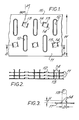
- Figure 1 shows part of a copper fin 11 from a motor vehicle radiator which has two rows of tubes (not shown) the tubes of one row being staggered with respect to tubes in the other row. Holes 12 are provided to receive the tubes which pass through the fins at right angles thereto.
- a plurality of circular holes 13 are plunged in the fin, splitting the circular piece of metal displaced into two semicircles 14 which are raised out of the fin with their free diameters uppermost and remaining attached to the fin by a short bridge extending round a small portion of the circumference of the original circle.
- the upstanding semicircles 14, act as spacing members to ensure a gap is maintained between fins which is approximately equal to the radius of the holes 13.
- dimension H is approximately half of dimension D. The dimensions are so chosen as to obtain a fin pitch of 14 fins per inch (25.4 millimetres).
- the shape of the spacing members 14, is such that it will prevent the fins nesting.
- Other shapes such as diamonds could be used, if they provided a spacing member with a wide free end.
- the spacing members are elongate and are set at an angle, A degrees from a line extending at right angles to the edge of the fin. In practice this means that in use of the radiator, if optimally installed, the spacing members will be set at an angle of incidence of A degrees to the air flow between the fins, which impinges on the leading edge 15 of the fin and hence on the leading face of the stack of fins, at right angles thereto.
- the spacing members are distributed along the length of each of the fins of the radiator, not only in the regions of slow moving air around the edges of the radiator matrix, but also in the region where the air flow rate is greatest.
- the spacing members are distributed between adjacent tubes in a row, and moreover that half are located directly upstream of tubes in the other row, thus turbulating the air flowing onto the tubes in the other row.
- the spacing members may need to be set at a different angle to the leading face of the radiator to achieve the. desired angle of incidence to the air flow.
- the radiator leading face is perpendicular to the mean incident air stream.
- the illustrated embodiment can be incorporated while retaining some advantage.
- the spacing members could even be a separate item inserted between the fins.
- the radiator may have different numbers of tube rows, different fin pitch or distribution or ratio of fins to spacing members.
Landscapes
- Physics & Mathematics (AREA)
- Engineering & Computer Science (AREA)
- Geometry (AREA)
- Thermal Sciences (AREA)
- Mechanical Engineering (AREA)
- General Engineering & Computer Science (AREA)
- Cooling, Air Intake And Gas Exhaust, And Fuel Tank Arrangements In Propulsion Units (AREA)
- Heat-Exchange Devices With Radiators And Conduit Assemblies (AREA)
- Details Of Heat-Exchange And Heat-Transfer (AREA)
Applications Claiming Priority (2)
| Application Number | Priority Date | Filing Date | Title |
|---|---|---|---|
| GB8204547 | 1982-02-16 | ||
| GB8204547 | 1982-02-16 |
Publications (2)
| Publication Number | Publication Date |
|---|---|
| EP0086559A2 true EP0086559A2 (de) | 1983-08-24 |
| EP0086559A3 EP0086559A3 (de) | 1984-01-11 |
Family
ID=10528377
Family Applications (1)
| Application Number | Title | Priority Date | Filing Date |
|---|---|---|---|
| EP83300209A Withdrawn EP0086559A3 (de) | 1982-02-16 | 1983-01-17 | Wärmetauscher |
Country Status (2)
| Country | Link |
|---|---|
| EP (1) | EP0086559A3 (de) |
| JP (1) | JPS58193092A (de) |
Cited By (11)
| Publication number | Priority date | Publication date | Assignee | Title |
|---|---|---|---|---|
| EP0106480A3 (de) * | 1982-09-10 | 1985-01-16 | Unipart Group Limited | Kühlrippen für Wärmetauscher |
| US4830102A (en) * | 1980-03-11 | 1989-05-16 | Kulkereskedelmi Transelektro Magyar Villamossagi Vallalat | Turbulent heat exchanger |
| EP0803695A3 (de) * | 1996-04-25 | 1998-08-26 | Denso Corporation | Rippenplatten-Wärmetauscher |
| US5975200A (en) * | 1997-04-23 | 1999-11-02 | Denso Corporation | Plate-fin type heat exchanger |
| EP1055897A1 (de) * | 1999-05-27 | 2000-11-29 | Valeo Thermique Moteur | Wärmetauscher mit verbesserter Positionierung von Rippen |
| EP1098157A3 (de) * | 1999-11-04 | 2002-02-13 | Alfred Schneider | Latentwärmespeicher |
| FR2866698A1 (fr) * | 2004-02-24 | 2005-08-26 | Valeo Thermique Moteur Sa | Echangeur de chaleur a ailettes avec pattes d'espacement |
| FR2866948A1 (fr) * | 2004-02-27 | 2005-09-02 | Valeo Thermique Moteur Sa | Echangeur de chaleur a deflecteur de flux ameliore |
| US7337831B2 (en) * | 2001-08-10 | 2008-03-04 | Yokohama Tlo Company Ltd. | Heat transfer device |
| FR3038977A1 (fr) * | 2015-07-17 | 2017-01-20 | Valeo Systemes Thermiques | Echangeur de chaleur a ailettes comprenant des persiennes ameliorees |
| CN108827055A (zh) * | 2018-07-30 | 2018-11-16 | 宁波奥克斯电气股份有限公司 | 一种翅片及换热器和具有该换热器的空调器 |
Families Citing this family (1)
| Publication number | Priority date | Publication date | Assignee | Title |
|---|---|---|---|---|
| JP6107686B2 (ja) * | 2014-01-29 | 2017-04-05 | 三菱電機株式会社 | フィンチューブ式熱交換器、その製造方法および空気調和機 |
Family Cites Families (4)
| Publication number | Priority date | Publication date | Assignee | Title |
|---|---|---|---|---|
| US3437134A (en) * | 1965-10-24 | 1969-04-08 | Borg Warner | Heat exchanger |
| DE2306562A1 (de) * | 1973-02-10 | 1974-08-15 | Volkswagenwerk Ag | Waermetauscher |
| DE2530064A1 (de) * | 1975-07-05 | 1977-01-27 | Volkswagenwerk Ag | Luftlamelle fuer einen leichtmetall- waermetauscher |
| NL8100334A (nl) * | 1980-01-28 | 1981-08-17 | Lummus Co | Buis met plaatvormige ribben en warmtewisselaar die met zulke ribben is uitgerust. |
-
1983
- 1983-01-17 EP EP83300209A patent/EP0086559A3/de not_active Withdrawn
- 1983-02-16 JP JP2299683A patent/JPS58193092A/ja active Pending
Cited By (16)
| Publication number | Priority date | Publication date | Assignee | Title |
|---|---|---|---|---|
| US4830102A (en) * | 1980-03-11 | 1989-05-16 | Kulkereskedelmi Transelektro Magyar Villamossagi Vallalat | Turbulent heat exchanger |
| EP0106480A3 (de) * | 1982-09-10 | 1985-01-16 | Unipart Group Limited | Kühlrippen für Wärmetauscher |
| EP0803695A3 (de) * | 1996-04-25 | 1998-08-26 | Denso Corporation | Rippenplatten-Wärmetauscher |
| US5975200A (en) * | 1997-04-23 | 1999-11-02 | Denso Corporation | Plate-fin type heat exchanger |
| EP1055897A1 (de) * | 1999-05-27 | 2000-11-29 | Valeo Thermique Moteur | Wärmetauscher mit verbesserter Positionierung von Rippen |
| FR2794226A1 (fr) * | 1999-05-27 | 2000-12-01 | Valeo Thermique Moteur Sa | Echangeur de chaleur, notamment pour vehicule automobile, muni de positionnement d'ailettes perfectionne |
| EP1098157A3 (de) * | 1999-11-04 | 2002-02-13 | Alfred Schneider | Latentwärmespeicher |
| US7337831B2 (en) * | 2001-08-10 | 2008-03-04 | Yokohama Tlo Company Ltd. | Heat transfer device |
| FR2866698A1 (fr) * | 2004-02-24 | 2005-08-26 | Valeo Thermique Moteur Sa | Echangeur de chaleur a ailettes avec pattes d'espacement |
| FR2866948A1 (fr) * | 2004-02-27 | 2005-09-02 | Valeo Thermique Moteur Sa | Echangeur de chaleur a deflecteur de flux ameliore |
| FR3038977A1 (fr) * | 2015-07-17 | 2017-01-20 | Valeo Systemes Thermiques | Echangeur de chaleur a ailettes comprenant des persiennes ameliorees |
| WO2017012867A1 (fr) * | 2015-07-17 | 2017-01-26 | Valeo Systemes Thermiques | Échangeur de chaleur a ailettes comprenant des persiennes améliorées |
| CN108369076A (zh) * | 2015-07-17 | 2018-08-03 | 法雷奥热系统公司 | 包括改进的百叶片的翅片热交换器 |
| US10914530B2 (en) | 2015-07-17 | 2021-02-09 | Valeo Systemes Thermiques | Fin heat exchanger comprising improved louvres |
| CN108827055A (zh) * | 2018-07-30 | 2018-11-16 | 宁波奥克斯电气股份有限公司 | 一种翅片及换热器和具有该换热器的空调器 |
| CN108827055B (zh) * | 2018-07-30 | 2024-05-10 | 宁波奥克斯电气股份有限公司 | 一种翅片及换热器和具有该换热器的空调器 |
Also Published As
| Publication number | Publication date |
|---|---|
| EP0086559A3 (de) | 1984-01-11 |
| JPS58193092A (ja) | 1983-11-10 |
Similar Documents
| Publication | Publication Date | Title |
|---|---|---|
| EP0219657B1 (de) | Zusammengesetzte Vorrichtung zur Wärmeabteilung mit abwechselnd gewandten Rippen versehenen Stiften für einen von oben nach unten verlaufenden Strom | |
| US4469167A (en) | Heat exchanger fin | |
| US4830102A (en) | Turbulent heat exchanger | |
| US6173758B1 (en) | Pin fin heat sink and pin fin arrangement therein | |
| US5318112A (en) | Finned-duct heat exchanger | |
| EP0086559A2 (de) | Wärmetauscher | |
| US6227289B1 (en) | Finned heat exchanger | |
| KR100543599B1 (ko) | 열교환기 | |
| US5062475A (en) | Chevron lanced fin design with unequal leg lengths for a heat exchanger | |
| CN1012281B (zh) | 热交换器 | |
| KR0127598Y1 (ko) | 공기조화기의 열교환기 | |
| US6170566B1 (en) | High performance louvered fin for a heat exchanger | |
| KR100197718B1 (ko) | 공기조화기의 열교환기 | |
| EP1977180B1 (de) | Gerippter rohrwärmetauscher | |
| EP3507560B1 (de) | Rippenverbesserungen für luftstrom mit niedriger reynoldsscher zahl | |
| KR0133025Y1 (ko) | 공기조화기의 열교환기 | |
| JPH1089875A (ja) | 空気調和機の熱交換器 | |
| JP3132413B2 (ja) | プレートフィンコイル | |
| KR0133026Y1 (ko) | 공기조화기의 열교환기 | |
| EP3575728B1 (de) | Kern eines wärmetauschers mit gewellten rippen | |
| KR100197709B1 (ko) | 공기조화기의 열교환기 | |
| JPH02242092A (ja) | 熱交換器 | |
| JPS616592A (ja) | フイン付熱交換器 | |
| CA1239927A (en) | High heat transfer means for flat tube and fin heat exchangers | |
| KR0127599Y1 (ko) | 공기조화기의 열교환기 |
Legal Events
| Date | Code | Title | Description |
|---|---|---|---|
| PUAI | Public reference made under article 153(3) epc to a published international application that has entered the european phase |
Free format text: ORIGINAL CODE: 0009012 |
|
| AK | Designated contracting states |
Designated state(s): DE FR GB IT SE |
|
| PUAL | Search report despatched |
Free format text: ORIGINAL CODE: 0009013 |
|
| AK | Designated contracting states |
Designated state(s): DE FR GB IT SE |
|
| STAA | Information on the status of an ep patent application or granted ep patent |
Free format text: STATUS: THE APPLICATION IS DEEMED TO BE WITHDRAWN |
|
| 18D | Application deemed to be withdrawn |
Effective date: 19841220 |
|
| RIN1 | Information on inventor provided before grant (corrected) |
Inventor name: BANTON, ANTHONY PHILLIP Inventor name: WILSON, CLIVE WINSTON |