EP0086713A1 - Mittel zum Zusammenstellen von Teilen, die in Bewegung gesetzt werden müssen - Google Patents
Mittel zum Zusammenstellen von Teilen, die in Bewegung gesetzt werden müssen Download PDFInfo
- Publication number
- EP0086713A1 EP0086713A1 EP83400286A EP83400286A EP0086713A1 EP 0086713 A1 EP0086713 A1 EP 0086713A1 EP 83400286 A EP83400286 A EP 83400286A EP 83400286 A EP83400286 A EP 83400286A EP 0086713 A1 EP0086713 A1 EP 0086713A1
- Authority
- EP
- European Patent Office
- Prior art keywords
- assembly according
- elements
- bar
- assembly
- section
- Prior art date
- Legal status (The legal status is an assumption and is not a legal conclusion. Google has not performed a legal analysis and makes no representation as to the accuracy of the status listed.)
- Granted
Links
- 210000002105 tongue Anatomy 0.000 claims description 28
- 230000000903 blocking effect Effects 0.000 claims description 7
- 238000007373 indentation Methods 0.000 claims description 4
- 238000004519 manufacturing process Methods 0.000 claims description 2
- 210000003323 beak Anatomy 0.000 description 5
- 238000009434 installation Methods 0.000 description 3
- 238000006073 displacement reaction Methods 0.000 description 2
- 238000000034 method Methods 0.000 description 2
- 208000031968 Cadaver Diseases 0.000 description 1
- 230000000712 assembly Effects 0.000 description 1
- 238000000429 assembly Methods 0.000 description 1
- 238000010276 construction Methods 0.000 description 1
- 230000000694 effects Effects 0.000 description 1
- 239000000463 material Substances 0.000 description 1
- 238000012986 modification Methods 0.000 description 1
- 230000004048 modification Effects 0.000 description 1
- 238000000465 moulding Methods 0.000 description 1
- 230000000284 resting effect Effects 0.000 description 1
- 238000010079 rubber tapping Methods 0.000 description 1
- 239000007787 solid Substances 0.000 description 1
Images





Classifications
-
- F—MECHANICAL ENGINEERING; LIGHTING; HEATING; WEAPONS; BLASTING
- F16—ENGINEERING ELEMENTS AND UNITS; GENERAL MEASURES FOR PRODUCING AND MAINTAINING EFFECTIVE FUNCTIONING OF MACHINES OR INSTALLATIONS; THERMAL INSULATION IN GENERAL
- F16D—COUPLINGS FOR TRANSMITTING ROTATION; CLUTCHES; BRAKES
- F16D1/00—Couplings for rigidly connecting two coaxial shafts or other movable machine elements
- F16D1/06—Couplings for rigidly connecting two coaxial shafts or other movable machine elements for attachment of a member on a shaft or on a shaft-end
- F16D1/08—Couplings for rigidly connecting two coaxial shafts or other movable machine elements for attachment of a member on a shaft or on a shaft-end with clamping hub; with hub and longitudinal key
- F16D1/0829—Couplings for rigidly connecting two coaxial shafts or other movable machine elements for attachment of a member on a shaft or on a shaft-end with clamping hub; with hub and longitudinal key with radial loading of both hub and shaft by an intermediate ring or sleeve
-
- E—FIXED CONSTRUCTIONS
- E05—LOCKS; KEYS; WINDOW OR DOOR FITTINGS; SAFES
- E05B—LOCKS; ACCESSORIES THEREFOR; HANDCUFFS
- E05B3/00—Fastening knobs or handles to lock or latch parts
-
- F—MECHANICAL ENGINEERING; LIGHTING; HEATING; WEAPONS; BLASTING
- F16—ENGINEERING ELEMENTS AND UNITS; GENERAL MEASURES FOR PRODUCING AND MAINTAINING EFFECTIVE FUNCTIONING OF MACHINES OR INSTALLATIONS; THERMAL INSULATION IN GENERAL
- F16B—DEVICES FOR FASTENING OR SECURING CONSTRUCTIONAL ELEMENTS OR MACHINE PARTS TOGETHER, e.g. NAILS, BOLTS, CIRCLIPS, CLAMPS, CLIPS OR WEDGES; JOINTS OR JOINTING
- F16B21/00—Means for preventing relative axial movement of a pin, spigot, shaft or the like and a member surrounding it; Stud-and-socket releasable fastenings
- F16B21/06—Releasable fastening devices with snap-action
- F16B21/065—Releasable fastening devices with snap-action with an additional locking element
-
- F—MECHANICAL ENGINEERING; LIGHTING; HEATING; WEAPONS; BLASTING
- F16—ENGINEERING ELEMENTS AND UNITS; GENERAL MEASURES FOR PRODUCING AND MAINTAINING EFFECTIVE FUNCTIONING OF MACHINES OR INSTALLATIONS; THERMAL INSULATION IN GENERAL
- F16B—DEVICES FOR FASTENING OR SECURING CONSTRUCTIONAL ELEMENTS OR MACHINE PARTS TOGETHER, e.g. NAILS, BOLTS, CIRCLIPS, CLAMPS, CLIPS OR WEDGES; JOINTS OR JOINTING
- F16B3/00—Key-type connections; Keys
- F16B3/06—Key-type connections; Keys using taper sleeves
-
- E—FIXED CONSTRUCTIONS
- E05—LOCKS; KEYS; WINDOW OR DOOR FITTINGS; SAFES
- E05B—LOCKS; ACCESSORIES THEREFOR; HANDCUFFS
- E05B63/00—Locks or fastenings with special structural characteristics
- E05B63/0056—Locks with adjustable or exchangeable lock parts
- E05B63/006—Locks with adjustable or exchangeable lock parts for different door thicknesses
Definitions
- the present invention relates to an assembly of parts to be set in motion, in particular in rotation, by action on one of the parts.
- the assembly according to the invention is essentially characterized in that it comprises at least three elements, one of which consists of an axis or a central bar provided with one or more mortises or grooves in which or which engage elastically a or several studs provided on a second element which surrounds the first over part of its height, the third element, which surrounds the first two and is possibly associated with other elements, ensuring the cohesion of the assembly.
- This new system of the invention has great ease of assembly. It has good mechanical strength thanks to the cooperation of the aforementioned elements, the third of which, possibly in combination with additional elements, ensures the locking of the tenons of the first in the mortises of the second.
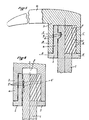
- the first embodiment shown in FIGS. 1, 2, 3 and 4 comprises an axis or a central bar 1 constituting the first element, a second element 2 mounted on the central bar 1 and a part 3 or the third element which comes to cover item 2.
- the lug 5 can be moved from its normal position in order to allow the introduction of the bar I.
- This elasticity of the tongue a brings back the tenon 5 to its normal position when it is opposite the mortise 4.
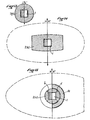
- Element 2 has a cylindrical shape at its base and externally (frg.2).
- the outer face of this element, in its reduced part, is also cylindrical.
- This cylindrical surface has a series of helical relief imprints having an appropriate pitch.
- the element has an inner cylindrical surface having a series of helical imprints e en. hollow, with an appropriate pitch, corresponding to the imprints d of the element 2.
- the part 3 is placed in place on the element 2 by making it undergo a rotation. At the end of the travel of the part 3, its face f in the form of a crown is pressed against the corresponding face g of the element 2.
- the part 3 thus ensures the cohesion of the example, it maintains in place the element 2 with its tenon 5 engaged in the mortise 4; solidarity in rotation also being also ensured by the square cross section of the bar 1 and of the strip of the element 2.
- the element 3, which in this case is identified with the handle 16, can be removed by rotation in the opposite direction to that which produces the locking.
- the tab a By spreading the tab a, the pin 5 is released from the mortise 4 and it is then possible to remove the bar 1 from the element 2.
- the bar 1 is of square section and includes a mortise 4 as in the first embodiment .
- the element 2 mounted on the bar 1 has at its base a section with a polygonal periphery (octagonal in this set).
- the lumen of the element 2 in which the bar 1 is engaged is of square section.
- the outer conical face of the element 2 is inclined in longitudinal section by an angle alpha on the axis of the assembly.
- the cylindrical inner face of the part 3 has a series of hollow, helical imprints with an appropriate pitch.
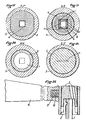
- An additional element 6 has a cylindrical outer surface in which there is provided a series of raised, helical imprints corresponding to the abovementioned indentations.
- the element 6 comprises a cylindrical full h-core and a collar i (fig. 7 and 10) whose external face is cylindrical, of the same radius as the aforementioned core and therefore in its extension.
- the internal face of this collar is conical and also forms in longitudinal section an angle alpha with the axis of the assembly; as above.
- This flange is inserted between the internal face of the element 3 and the external face of the element 2.
- the bar 1 easily penetrates into the element 2 thanks to the chamfer 7 at its end and to the chamfer m of the element 2.
- the elasticity of the tongues has the tenons 5 or 5 ′ being remade in the mortises 4 or 4 ′ as soon as the bar 1 is in place.
Landscapes
- Engineering & Computer Science (AREA)
- General Engineering & Computer Science (AREA)
- Mechanical Engineering (AREA)
- Mutual Connection Of Rods And Tubes (AREA)
- Securing Of Glass Panes Or The Like (AREA)
Applications Claiming Priority (2)
| Application Number | Priority Date | Filing Date | Title |
|---|---|---|---|
| FR8202560 | 1982-02-17 | ||
| FR8202560A FR2521657B1 (fr) | 1982-02-17 | 1982-02-17 | Dispositif d'assemblage de pieces devant etre mises en mouvement |
Publications (2)
| Publication Number | Publication Date |
|---|---|
| EP0086713A1 true EP0086713A1 (de) | 1983-08-24 |
| EP0086713B1 EP0086713B1 (de) | 1986-04-23 |
Family
ID=9271055
Family Applications (1)
| Application Number | Title | Priority Date | Filing Date |
|---|---|---|---|
| EP83400286A Expired EP0086713B1 (de) | 1982-02-17 | 1983-02-10 | Mittel zum Zusammenstellen von Teilen, die in Bewegung gesetzt werden müssen |
Country Status (3)
| Country | Link |
|---|---|
| EP (1) | EP0086713B1 (de) |
| DE (1) | DE3363136D1 (de) |
| FR (1) | FR2521657B1 (de) |
Cited By (1)
| Publication number | Priority date | Publication date | Assignee | Title |
|---|---|---|---|---|
| NL1041170B1 (nl) * | 2015-02-04 | 2016-10-12 | Themans Hang En Sluitwerk B V | Bedieningsinrichting en werkwijze voor het produceren van zo een bedieningsinrichting |
Families Citing this family (1)
| Publication number | Priority date | Publication date | Assignee | Title |
|---|---|---|---|---|
| DE3810324A1 (de) * | 1988-03-26 | 1989-10-12 | Alfred Fent | Schnellverschluss |
Citations (3)
| Publication number | Priority date | Publication date | Assignee | Title |
|---|---|---|---|---|
| FR16721E (fr) * | 1910-10-08 | 1913-04-08 | Claudius Gros | Dispositif de montage des boutons de portes |
| CH420737A (de) * | 1962-07-23 | 1966-09-15 | Naimer H L | Einrichtung zur Sicherung der gegenseitigen Unbeweglichkeit zweier aneinandergepresster Teile |
| DE1930679A1 (de) * | 1969-06-18 | 1971-01-07 | Hugo Haussels Fa | Loesbare,auf beliebige Tuerdicke einstellbare Tuerdrueckerklemmbefestigung |
Family Cites Families (3)
| Publication number | Priority date | Publication date | Assignee | Title |
|---|---|---|---|---|
| US750675A (en) * | 1904-01-26 | mighelin | ||
| FR1366109A (fr) * | 1963-05-28 | 1964-07-10 | Assemblage perfectionné pour pièces de machines | |
| FR2426822A1 (fr) * | 1978-05-26 | 1979-12-21 | Siamp Cedap Reunies | Dispositif de serrage ou de blocage d'un objet sur une tige |
-
1982
- 1982-02-17 FR FR8202560A patent/FR2521657B1/fr not_active Expired
-
1983
- 1983-02-10 DE DE8383400286T patent/DE3363136D1/de not_active Expired
- 1983-02-10 EP EP83400286A patent/EP0086713B1/de not_active Expired
Patent Citations (3)
| Publication number | Priority date | Publication date | Assignee | Title |
|---|---|---|---|---|
| FR16721E (fr) * | 1910-10-08 | 1913-04-08 | Claudius Gros | Dispositif de montage des boutons de portes |
| CH420737A (de) * | 1962-07-23 | 1966-09-15 | Naimer H L | Einrichtung zur Sicherung der gegenseitigen Unbeweglichkeit zweier aneinandergepresster Teile |
| DE1930679A1 (de) * | 1969-06-18 | 1971-01-07 | Hugo Haussels Fa | Loesbare,auf beliebige Tuerdicke einstellbare Tuerdrueckerklemmbefestigung |
Cited By (1)
| Publication number | Priority date | Publication date | Assignee | Title |
|---|---|---|---|---|
| NL1041170B1 (nl) * | 2015-02-04 | 2016-10-12 | Themans Hang En Sluitwerk B V | Bedieningsinrichting en werkwijze voor het produceren van zo een bedieningsinrichting |
Also Published As
| Publication number | Publication date |
|---|---|
| EP0086713B1 (de) | 1986-04-23 |
| FR2521657A1 (fr) | 1983-08-19 |
| FR2521657B1 (fr) | 1986-04-18 |
| DE3363136D1 (en) | 1986-05-28 |
Similar Documents
| Publication | Publication Date | Title |
|---|---|---|
| EP3756501B1 (de) | Befestigungsvorrichtung für armband | |
| LU82605A1 (fr) | Ensemble serrure a barillet et cle pour cette serrure et procede de fabrication de la cle | |
| EP0793024B1 (de) | Verbindungs- und Verriegelungsvorrichtung für teleskopische Rohre | |
| WO2004043306A1 (fr) | Cage intervertebrale a lame d’ancrage mediane | |
| CA2840869A1 (fr) | Embout amovible de baton | |
| EP3870866A1 (de) | Drehbares befestigungszubehör | |
| EP0983411B1 (de) | Schlüssel mit bewegbarem stift, sicherheitsdrehzylinder und damit ausgerüstetes schloss | |
| EP0359885A1 (de) | Schlüssel mit Schiebeelement, Sicherheitszylinder, und Schloss mit solchen Zylindern | |
| FR2604475A1 (fr) | Paumelle a blocage axial de la broche pour porte ou fenetre | |
| EP0262059B1 (de) | Schlüssel und Schloss | |
| EP0647752A2 (de) | Entkuppelbares Schloss für Kraftfahrzeuge und dgl. | |
| EP3658724B1 (de) | Sicherheitsschloss und flachschlüsselanordnung | |
| EP0086713B1 (de) | Mittel zum Zusammenstellen von Teilen, die in Bewegung gesetzt werden müssen | |
| FR3080327A1 (fr) | Instrument d'ecriture multifonction | |
| WO2002070054A1 (fr) | Seringue, ou dispositif similaire | |
| EP0700479B1 (de) | Schlüssel mit zwei abschrägungen am ende für ein sicherheitzylinderschloss und zylinderschloss dafür | |
| FR2635352A1 (fr) | Cylindre de surete pour serrure, et cle correspondante | |
| EP0770745A1 (de) | Abnehmbarer Griff für Türen oder Fenster insbesondere in Metallprofilen | |
| EP4123187B1 (de) | Befestigung für die vorübergehende montage von strukturen | |
| FR2802233A1 (fr) | Barillet de surete muni d'un moyen anti-vibreur | |
| FR2802234A1 (fr) | Barillet de surete muni d'un moyen anti-crochetage | |
| EP0367649B2 (de) | Sicherheitsschloss mit Zuhaltungsscheiben | |
| EP0940529A1 (de) | Doppelsicherheitszylinder | |
| FR2924771A1 (fr) | Systeme d'encliquetage avec verrouillage entre deux elements | |
| FR2769658A1 (fr) | Barillet de serrure pour serrure de securite |
Legal Events
| Date | Code | Title | Description |
|---|---|---|---|
| PUAI | Public reference made under article 153(3) epc to a published international application that has entered the european phase |
Free format text: ORIGINAL CODE: 0009012 |
|
| AK | Designated contracting states |
Designated state(s): BE DE GB IT NL |
|
| 17P | Request for examination filed |
Effective date: 19830722 |
|
| GRAA | (expected) grant |
Free format text: ORIGINAL CODE: 0009210 |
|
| ITF | It: translation for a ep patent filed | ||
| AK | Designated contracting states |
Kind code of ref document: B1 Designated state(s): BE DE GB IT NL |
|
| REF | Corresponds to: |
Ref document number: 3363136 Country of ref document: DE Date of ref document: 19860528 |
|
| PLBE | No opposition filed within time limit |
Free format text: ORIGINAL CODE: 0009261 |
|
| STAA | Information on the status of an ep patent application or granted ep patent |
Free format text: STATUS: NO OPPOSITION FILED WITHIN TIME LIMIT |
|
| 26N | No opposition filed | ||
| PGFP | Annual fee paid to national office [announced via postgrant information from national office to epo] |
Ref country code: GB Payment date: 19890228 Year of fee payment: 7 |
|
| PGFP | Annual fee paid to national office [announced via postgrant information from national office to epo] |
Ref country code: DE Payment date: 19900123 Year of fee payment: 8 |
|
| PGFP | Annual fee paid to national office [announced via postgrant information from national office to epo] |
Ref country code: BE Payment date: 19900130 Year of fee payment: 8 |
|
| PG25 | Lapsed in a contracting state [announced via postgrant information from national office to epo] |
Ref country code: GB Effective date: 19900210 |
|
| ITTA | It: last paid annual fee | ||
| GBPC | Gb: european patent ceased through non-payment of renewal fee | ||
| PG25 | Lapsed in a contracting state [announced via postgrant information from national office to epo] |
Ref country code: BE Effective date: 19910228 |
|
| PGFP | Annual fee paid to national office [announced via postgrant information from national office to epo] |
Ref country code: NL Payment date: 19910228 Year of fee payment: 9 |
|
| PG25 | Lapsed in a contracting state [announced via postgrant information from national office to epo] |
Ref country code: DE Effective date: 19911101 |
|
| PG25 | Lapsed in a contracting state [announced via postgrant information from national office to epo] |
Ref country code: NL Effective date: 19920901 |
|
| NLV4 | Nl: lapsed or anulled due to non-payment of the annual fee |