EP0086766A2 - Anlage zum Vulkanisieren von Reifen - Google Patents
Anlage zum Vulkanisieren von Reifen Download PDFInfo
- Publication number
- EP0086766A2 EP0086766A2 EP83850037A EP83850037A EP0086766A2 EP 0086766 A2 EP0086766 A2 EP 0086766A2 EP 83850037 A EP83850037 A EP 83850037A EP 83850037 A EP83850037 A EP 83850037A EP 0086766 A2 EP0086766 A2 EP 0086766A2
- Authority
- EP
- European Patent Office
- Prior art keywords
- autoclave
- lines
- vulcanization
- evacuation
- connection
- Prior art date
- Legal status (The legal status is an assumption and is not a legal conclusion. Google has not performed a legal analysis and makes no representation as to the accuracy of the status listed.)
- Granted
Links
Images



Classifications
-
- B—PERFORMING OPERATIONS; TRANSPORTING
- B29—WORKING OF PLASTICS; WORKING OF SUBSTANCES IN A PLASTIC STATE IN GENERAL
- B29C—SHAPING OR JOINING OF PLASTICS; SHAPING OF MATERIAL IN A PLASTIC STATE, NOT OTHERWISE PROVIDED FOR; AFTER-TREATMENT OF THE SHAPED PRODUCTS, e.g. REPAIRING
- B29C35/00—Heating, cooling or curing, e.g. crosslinking or vulcanising; Apparatus therefor
- B29C35/02—Heating or curing, e.g. crosslinking or vulcanizing during moulding, e.g. in a mould
- B29C35/0227—Heating or curing, e.g. crosslinking or vulcanizing during moulding, e.g. in a mould using pressure vessels, e.g. autoclaves, vulcanising pans
-
- B—PERFORMING OPERATIONS; TRANSPORTING
- B29—WORKING OF PLASTICS; WORKING OF SUBSTANCES IN A PLASTIC STATE IN GENERAL
- B29D—PRODUCING PARTICULAR ARTICLES FROM PLASTICS OR FROM SUBSTANCES IN A PLASTIC STATE
- B29D30/00—Producing pneumatic or solid tyres or parts thereof
- B29D30/0016—Handling tyres or parts thereof, e.g. supplying, storing, conveying
-
- B—PERFORMING OPERATIONS; TRANSPORTING
- B29—WORKING OF PLASTICS; WORKING OF SUBSTANCES IN A PLASTIC STATE IN GENERAL
- B29D—PRODUCING PARTICULAR ARTICLES FROM PLASTICS OR FROM SUBSTANCES IN A PLASTIC STATE
- B29D30/00—Producing pneumatic or solid tyres or parts thereof
- B29D30/06—Pneumatic tyres or parts thereof (e.g. produced by casting, moulding, compression moulding, injection moulding, centrifugal casting)
- B29D30/0601—Vulcanising tyres; Vulcanising presses for tyres
-
- B—PERFORMING OPERATIONS; TRANSPORTING
- B29—WORKING OF PLASTICS; WORKING OF SUBSTANCES IN A PLASTIC STATE IN GENERAL
- B29L—INDEXING SCHEME ASSOCIATED WITH SUBCLASS B29C, RELATING TO PARTICULAR ARTICLES
- B29L2017/00—Carriers for sound or information
- B29L2017/001—Carriers of records containing fine grooves or impressions, e.g. disc records for needle playback, cylinder records
- B29L2017/003—Records or discs
- B29L2017/005—CD''s, DVD''s
Definitions
- the present invention relates to a plant for the vulcanization of tyres, for example a plant of the kind in which used tyres are given a new tread, i.e. are retreaded.
- Previously disclosed plants for this purpose comprise a circular cylindrical autoclave with an essentially horizontal axis of symmetry, inside which the tyre units arranged for vulcanization are contained and are exposed to the combination of heat and pressure required in order to provide the tyres with new treads by vulcanization.
- the used tyres which are to be processed in the plant are prepared by grinding away any remaining tread, and by buffing and filling any damage, known as pot-holes, are treated by a process known as pasting, and are then fitted with a peripheral tread all around the tyre, thereby producing a casing suitable for vulcanization.
- the casings prepared in this way are fitted onto a split rim with an inner tube inside the casing, and with an elastic outer cover, known as the envelope, which is sealed against the rim in such a way as to produce an e: l closed space between the outer cover and the tyre casing.
- the inner tube is provided with a pressure connection nipple projecting from the rim for the supply of compressed air to the inner tube
- the outer cover is provided with a connecting nipple for the evacuation of the space located between the outer cover and the tyre casing.
- the tyre unit which has been prepared in this fashion is referred to in the following as the "tyre vulcanization unit" or simply as the "vulcanization unit".
- the autoclave is dimensioned for the simultaneous processing of a specific number of vulcanization units.
- the vulcanization units are hung inside the autoclave on supports which, in order to facilitate the charging and unloading of the autoclave, are arranged for movement on a conveyor track rigidly arranged inside the autoclave.
- a similar conveyor track can be arranged outside the autoclave, which, when the autoclave is open, can be connected to the conveyor track arranged inside the autoclave, so that a number of vulcanization units may be hung on the supports outside the autoclave and then introduced into the autoclave one at a time or, with the supports connected together, as a group, and on being unloaded from the autoclave taken out therefrom one at a time or as a group connected together.
- each of the individual vulcanization units must be connected to a source of corn-pressed air in order to supply compressed air to the inner tube, and to the environment outside the autoclave in order to evacuate the space between the outer cover and the tyre casing.
- the autoclaves in the plants previously known are provided with a number of pressure connection nipples corresponding to the number of vulcanization units which are to be processed in the autoclave, said nipples being arranged at a distance from each other along the longitudinal direction of the autoclave, which corresponds to the distance between the adjacent vulcanization units.
- Each of the pressure connection nipples is suitably provided on the outside of the autoclave with its own shut-off valve and is connected to a source of compressed air.
- a number of evacuation nipples corresponding to the number of vulcanization units is arranged inside the autoclave, said evacuation nipples being connected to the environment outside the autoclave, suitably via an evacuation line.
- Each of the evacuation connection nipples is also capable of being shut-off from the outside by means of its own shut--off valve.
- each of the individual pressure connection nipples inside the autoclave is connected by means of a flexible compressed air hose to the pressure connection nipple of the inner tube inside the vulcanization unit, and each of the individual connecting nipples from the outer cover is connected by means of a flexible hose to the evacuation nipples inside the autoclave.
- the autoclave is closed, whereupon the process therein is started up by increasing the pressure inside the autoclave, for example to about 8 kp/cm 2 , and by raising the temperature, for example to 90 - 130°C.
- the inner tubes inside the vulcanization units are subjected to a pressure of about 6 kp/cm 2 whilst the space between the outer cover and the casing is connected to the evacuation line.
- the pressure is reduced both in the autoclave and inside the inner tubes, and the heating is interrupted.
- the autoclave is then opened, whereupon the vulcanized units are taken out of the autoclave once the flexible connection hoses have been removed from the connecting nipples of each of the individual vulcanization units.
- connection operation takes a long time, which reduces the effective time during which the autoclave may be used for its intended purpose.
- the object of the present invention is to provide a plant for the vulcanization of tyres, in which said connection operations have been simplified to a great extent, whereby the disadvantages associated with previously known plants are avoided or are reduced to a great extent.
- a further aim of the invention is to provide said simplifications by simple means, and in such a way that existing plants may be modified without the need for too much rebuilding work in order
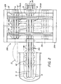
- the plant in accordance with the invention illustrated in FIGs 1 - 4 comprises a circular cylindrical autoclave 1 having a horizontal axis of symmetry.
- the autoclave is supported on its base by legs 2.
- One of the end walls of the autoclave is in the form of a door capable of being opened and closed and consisting essentially of a rigid domed cover 3 which, by being swung to one side in the manner indicated by the dotted lines in FIG 2, can be made to expose the whole of a loading opening having essentially the same cross-section as the cross--section of the rest of the autoclave.
- Inside the autoclave and extending along the entire length of the cylindrical casing are arranged three conveyor tracks, - a supporting conveyor track 4 and two lateral conveyor tracks 5 and 6 running parallel with it.
- the supporting conveyor track 4 which is arranged in the vertical symmetry plane of the autoclave, consists of a square hollow section 7 which is attached at the top to the inside of the casing of the autoclave, for instance by welding.
- the hollow section 7 of the supporting conveyor track 4 is open in direction downwards by means of a central, longitudinal slot 8 which extends for the entire length of the section.
- a number of wheeled trolleys 9 having supporting yokes 10 which carry supporting devices 11 projecting downwards through the slot 8 and designed as supporting hooks having a free horizontal shank intended, when engaged in the rim of a tyre vulcanization unit 12 of the type initially described to be capable of supporting the latter.
- the supporting conveyor track 4 In the supporting conveyor track 4 are arranged the same number of trolleys 9 provided with supporting yokes 10 and supporting devices 11 as the number of vulcanization units 12 which are to be processed simultaneously in the autoclave 1.
- the trolleys 9 may be interconnected so as to move along the supporting conveyor track simultaneously, or may be capable of being left independent of each other so as to permit individual movement.
- the lateral conveyor tracks 5 and 6 arranged parallel with the supporting conveyor track 4 each consists of a continuous, square hollow section 13 and 14 which, like the square hollow section 7, is provided on its bottom face with a longitudinal slot running the entire length of the section.
- the hollow sections 13 and 14 are designed to accept trolleys 15 and 16 fitted with yokes and running along the inside of the sections, said trolleys carrying supporting means 17 and 18 in the form of rods.
- the supporting means 17 and 18 are connected at their lower ends to U-shaped supporting sections 19 and 20, inside which are arranged bunches of lines 21 and 22.
- the bunches of lines 21 and 22 consist of rigid tubes, each bunch of lines having the same number of tubes as the number of vulcanization units 12 which are to be processed simultaneously in the autoclave.
- each of the ends of the individual tubes making up the bunch of lines is fitted with a connection nipple for connecting a flexible hose. From this point the tubes extend in progressively increasing lengths, whereby each tube is terminated by a connection nipol8 for the connection of a flexible hose.
- the lengths of the tubes are selected so that the extremity of each tube coincides with the position of the vulcanization unit 12 to which the tube is intended to be connected.
- the tubes in the bunch of lines 21 are intended to serve as evacuation lines, whereas the tubes in the bunch of lines 22. are intended to act as compressed air supply lines.
- each of the individual vulcanization units is connected by means of a flexible hose on one hand to an evacuation line for evacuating the space between the outer cover and the tyre casing of the vulcanization unit, and on the other to a compressed air supply line for the supply of compressed air to the inner tube of the vulcanization unit 12.
- the two bunches of lines 21 and 22 are arranged in a suitable fashion, for instance by means of a carrier 23 (FIG 3), to move simultaneously together with the supporting devices 11 carrying the vulcanization units 12, so that the vulcanization units 12 and the bunches of lines 21 and 22 are movable into and out of the autoclave as a single unit with the tubes in the bunches of lines being connected to their appropriate vulcanization unit via flexible hoses.
- evacuation connection means on the one hand in the form of a number of evacuation connection nipples 24 whose number corresponds to the number of vulcanization units capable of simultaneous processing in the autoclave, and on the other hand in the form of a similar number of compressed air connection nipples 25. All the connection nipples pass radially through the casing of the autoclave 1, and each of the nipples is provided outside the casing with its own shut-off valve 26 and 27. Outside the valves 26 the evacuation nipples 24 are connected to an evacuation line, and outside the valves 27 the compressed air connection nipples 25 are connected to a source of compressed air.
- each of the individual vulcanization units 12 may be connected to the source of compressed air for the supply of compressed air and may be connected to the evacuation line.
- connection nipples 24 and 25 are located in the immediate vicinity of the loading opening of the autoclave 1 the connection of the flexible hoses between the connection nipples 24 and the bunch of lines 21 and between the connection nipples 25 and the bunch of lines 22 can be performed by a single person standing outside the autoclave at its loading opening.
- the shut-off valves 26 and 27 may also be operated from this position.
- a conveyor device 28 resembling an overhead crane is arranged in front of the autoclave at its opening end.
- the conveyor device 28 is arranged at a sufficient distance from the autoclave to permit the opening and closing of the door 3 and to enable the necessary work involved at the opening of the autoclave to be performed without inconvenience.
- the conveyor device 28 consists of a strong supporting frame having two supporting beams 29 running parallel with the autoclave, which at their ends are connected to each other by means of two transverse supporting beams 30.
- the supporting frame is supported at its corners by four pillars 3i.
- the supporting beams 29 are connected to each other by means of two transverse overhead crane beams which on their underside are shaped as hollow sections inside which overhead crane trolleys 33 move along the overhead crane beams.
- the overhead crane trolleys 33 carry on their undersides two complete sets of conveyor tracks 34A and 34B.
- the two sets of conveyor tracks 34A and 348 are connected rigidly to each other and are movable together with the overhead.
- Each of the two individual sets of conveyor tracks 34A and 34B consists of three conveyor tracks of the same design as the conveyor tracks inside the autoclave and thus comprises a central supporting conveyor track 4 and two lateral conveyor tracks 5 and 6 arranged on opposite sides thereof.
- Each of the sets of conveyor tracks 34A and 34B is equipped with a set of supporting trolleys having supporting devices to carry the vulcanization units together with the supporting trolleys and bunches of lines of the design described above in connection with the specification of the conveyor tracks arranged inside the autoclave.
- the design of the conveyor tracks harmonizes in the appropriate parts with the design illustrated in FIG 4.
- the beam 30 is provided at its mid point with an articulated couoling unit 35 consisting of conveyor tracks of the same design as the conveyor tracks arranged inside the autoclave 1.
- the coupling unit 35 can thus be made to adopt the position shown in FIG 2, in which the coupling unit 35 interconnects the conveyor tracks inside the autoclave and the set of conveyor tracks 34B in the conveyor device, thereby enabling a complete batch of vulcanization units to be moved into or removed from the autoclave.
- This movement can be achieved by means of a suitable drive arrangement, for example a winch 36 or some other appropriate drive means.
- rhe pivoting movement of the coupling device 35 is achieved by means of a power unit not shown in the figure.
- FIG 2 illustrates the stage of the operation at which a batch of vulcanization units 12 which has been processed in the autoclave is removed from the autoclave by means of the winch 36.
- the coupling unit 35 is thereby in its lowered position, enabling the vulcanization units 12 together with the bunches of lines ⁇ 1 and 22 to be transferred to the set of conveyor tracks 34B in the conveyor device 29.
- the overhead crane trolleys 33 are then made to move the two sets of conveyor tracks 34A and 34B sideways so that the set of conveyor tracks 34B is caused to adopt the position shown in FIG 2 with dotted lines, whereby the set of conveyor tracks 34A is caused to adopt a position directly in line with the coupling component 35 and the conveyor tracks inside the autoclave.
- the set of transport tracks 34A now carries a new batch of vulcanization units 12 which were hung on the set of conveyor tracks 34A during the period when the previous batch of vulcanization units was being processed inside the autoclave, every vulcanization unit 12 being connected to the appropriate evacuation line or compressed air supply line by means of flexible hoses.
- connection nipples on the ends of each of the bunches of lines 21 and 22 are connected by means of flexible hoses to the evacuation connection nipples 24 or to the compressed air connection nipples 25 at the end of the autoclave 1.
- This connection operation may be performed by a single person standing outside the autoclave at its end.
- the batch of vulcanization units 12 removed from the autoclave in the previous operation is now suspended in the set of conveyor tracks 34A in the position shown by dotted lines in FIG 2.
- the vulcanization units whose processing was completed in the previous stage may be removed from the set of conveyor tracks 34B by disconnecting the hoses and by lifting the vulcanization units off their supports.
- each individual vulcanization unit is connected by means of flexible hoses to the appropriate compressed air supply line or evacuation line in the respective bunch of lines, so that a new batch of connected vulcanization units can be introduced into the autoclave as soon as the processed batch has been removed.
- the pressure inside the autoclave is released and the supply of heat is interrupted.
- the compressed air supply line is shut--off, whereupon the autoclave is opened.
- the connecting hoses between the connection nipples 24 and 25 and the bunches of lines 21 and 22 are then disconnected, whereupon the finished batch of vulcanization units is fed out, once the coupling unit 35 has been swung down, onto the set of conveyor tracks 34A until it is fully accommodated on the conveyor device 28.
- the set of conveyor tracks 34B supporting therein an already connected batch of vulcanization units will be caused to adopt the position shown in FIG 2 by means of solid lines, whereupon the set of prepared vulcanization units can be introduced into the autoclave.
- FIGs 5 - 7 is illustrated an alternative embodiment of a plant in accordance with the invention.
- a supporting conveyor track 4 Inside the autoclave 1 are arranged a supporting conveyor track 4, as well as two lateral conveyor tracks 5A and 6A as in the embodiment described previously.
- the supporting conveyor track 4 is, as in the embodiment described previously, arranged in the vertical symmetry plane of the autoctave and is attached at the top to the cylindrical casing of the autoclave.
- the lateral conveyor tracks 5A and 6A in this embodiment are, however, both arranged on one side of the supporting conveyor track 4, running parallel with it and with each other, as shown in the figures, especially in FIG 7.
- Each of the lateral conveyor tracks 5A and 6A is adapted to carry in its supporting means 18 a section 37, in which are arranged a complete bunch of compressed air supply lines as well as a complete bunch of evacuation li,nes.
- the section 37 preferably is designed to have an I-shaped cross-section, the bunch of evacuation lines 21 being situated on one side of the web of said section 37 and the bunch of compressed air supply lines 22 being situated on the other side thereof.
- the supporting conveyor track 4 and the lateral conveyor tracks 5A and 6A are identical in other respects with the corresponding conveyor tracks in the Embodiment described previously, for which reason they are not described in greater detail here.
- the bunches of lines 21 and 22 are also substantially identical with the bunches of lines in the embodiments described previously, differing in that each supporting section 37 carries both a bunch of compressed air connection lines 2.2 and a bunch of evacuation lines 21.
- the plant includes two complete sets of lines of the afore-mentioned kind, one of the sets of lines during a particular vulcanization operation to be situated inside the autoclave inserted into the lateral conveyor track 6A together with a batch of vulcanization units 12 carried by the supporting conveyor track, whereby in the subsequent vulcanization operation the second set of lines to be situated inside the autoclave inserted into the lateral conveyor track 5A together with a new batch of vulcanization units 12.
- a supporting structure 39 In front of the autoclave 1 on its input side is arranged a supporting structure 39 supported on pillars 38 situated at an appropriate distance from the opening of the autoclave to provide adequate working space in front of it.
- the supporting structure 39 carries in line with the conveyor tracks arranged inside the autoclave 1 a supporting conveyor track 4 and two lateral conveyor tracks 5A and 6A designed so as to be substantially identical with the corresponding conveyor tracks inside the autoclave and having an effective length which corresponds to the length of the autoclave.
- a coupling unit for each of the conveyor tracks is arranged between the supporting structure 39 and the opening of the autoclave is arranged a coupling unit for each of the conveyor tracks, said coupling unit being capable in a manner not shown in greater detail of being moved or swung out of the way so as to permit the closing or the opening of the autoclave.
- the supporting conveyor track 4 extends beyond the ends of the lateral conveyor tracks 5A and 6A and then following a semi-circular arc after which it extends in the direction back towards the autoclave, preferably in a straight line, to be connected again via an S-shaped bend to the coupling unit by means of switch not shown here in any great detail.
- the plant includes not only two complete sets of bunches of lines 21 and 22, but also two complete sets of supporting devices 11 for carrying two complete batches of vulcanization units 12.
- the hose connections for connecting the bunches of lines 21 and 22 to the evacuation connection nipples 24 and to the compressed air connection nipples 25 in the autoclave are disconnected.
- the hose connections between the vulcanization units and the bunch of lines are disconnected, whereupon the vulcanization unit is led via the afore-mentioned switch in the supporting conveyor track 4 along the afore-mentioned S-shaped bend to a holding position along the straight part of the track 4, as shown in FIG 6.
- the bunch of lines is fed from the autoclave in a linear fashion into a rear position in the lateral conveyor track 6A outside the autoclave, as indicated by an arrow alongside this track in FIG 6.
- two complete bunches of lines 21 and 22 are supported by the intermediate lateral conveyor track 5A, and a new batch of vulkanization units 12 for introduction into the autoclave together with the bunches of lines 21 and 22 is suspended in the supporting conveyor track 4 by means of carrier means 11.
- the finished vulcanization units 12 which have been removed from the autoclave are removed from the carrier means 11, these are further moved along the semi-circular part of the supporting conveyor track 4 until they are in level with the bunches of lines 21 and 22 supported by the lateral conveyor track bA, whereupon a new batch of vulcanization units 12 is hung on the supporting devices and is connected by means of flexible hoses to the appropriate connection nipples in the evacuation lines 21 and the compressed air supply lines 22 in the bunch, so as to produce a new ready-connected batch of vulcanization units 12 for introduction into the autoclave together with the bunch of lines being carried in the lateral conveyor track 6A.
- the movement of the bunches of lines 21 and 22 along the conveyor tracks and the movement of the vulcanization units into the autoclave can be achieved by means of a suitable drive means, for instance by providing a cable drive via a winch 40 or by some other means.
- FIGs 8 and 9 illustrate a further alternative embodiment of the plant in accordance with the invention.
- a supporting conveyor track 4 Inside the autoclave 1 is arranged a supporting conveyor track 4 and in a symmetrical relationship thereto two lateral conveyor tracks 5B and 68.
- the design and positioning of the tracks are identical with the arrangement in the first embodiment described above.
- the bunch of lines 21A for evacuation and the bunch of lines 21B for the supply of compressed air are both carried by the supporting means 18 on one of the lateral conveyor tracks 6B, and during the following vulcanization operation on the other lateral conveyor track 5B.
- the bunches of lines 21A and 21B do not consist of rigid tubes, but of flexible hoses 41 for evacuation and 42 for the supply of compressed air.
- the supporting means 18 extend vertically and are designed in the form of vertical hose clamps to which the hoses 41 and 42 are clipped or attached in some other way. Thus, between the adjacent supporting means 18 no support is provided for the hoses 41 and 42, thereby allowing the entire bunch of hoses to flex, enabling the bunch of hoses to be guided along a curved path. Unlike the bunches of lines which consist of rigid tubes, all the hoses 41 and 42 extend along the entire length of the cylindrical part of the autoclave. Furthermore, both ends of each hose are fitted with a connection nipple enabling them to be connected to the compressed air connection nipples or to the evacuation connection nipples at the end of the autoclave.
- Each hose 42 intended for connection to the compressed air supply is fitted with a check valve at either end ahead of the connection nipple, said check valves being fitted in such a way that the supply of compressed air into the hose via the connection nipples at the ends of the hoses will be permitted whilst the flow of compressed air in the opposite direction is blocked.
- the evacuation hose lines 41 are similarly fitted at each end with a check valve, said valves being fitted in such a way that the outward flow of gas via the ends of the lines is permitted whereas the supply of compressed air via said ends of the hose line is blocked.
- Each of the hose lines 41 and 42 is also equipped with a branch having a connection nipple for connection to the evacuation nipple or to the compressed air supply nipple on a particular vulcanization unit.
- the hose line nipples 41 and 42 outside the autoclave can be connected to the respective unit in a batch of vulcanization units in order to provide either a supply of compressed air or evacuation.
- the conveyor device arranged outside the autoclave is to a great extent similar with the device shown in FIG 6.
- the significant difference is that all three conveyor tracks 4, 5B and 68 are guided via a semi-circular bend back towards the autoclave and are connected via a switch arrangement not shown, directly in line with the conveyor tracks inside the autoclave.
- both the carrier means 11 for the vulcanization units and the supporting means 18 for the bunch of hose lines are passed via the switch through the S-shaped curve and over its entire length onto the straight part of the tracks.
- the switch is then switched over so that a prepared batch of vulcanization units 12 on the other straight part of the track together with the bunch of hose lines 41, 42 carried in the lateral conveyor track 5B may be introduced into the autoclave and connected in the previously described manner.
- both the interconnected supporting devices 11 for the vulcanization units and the bunch of hose lines 41, 42 carried on the supporting means 18 are passed along the semi-circular part of the track, over its entire length and onwards along the straight part of the track, where a new batch of vulcanization units 12 may be attached and connected to the respective hose line in the previously described manner.
- FIGs 10 and 11 illustrate in diagrammatic form a further modified embodiment in accordance with the invention, which is particularly advantageous with regard to the bunch of lines containing compressed air and evacuation lines and with regard to the connecting of the evacuation lines to the evacuation connection nipples inside the autoclave in the vicinity of its loading opening.
- a supporting conveyor track 4 and parallel therewith and adjacent to it a lateral conveyor track 6C.
- the conveyor tracks 4 and 6C which are permanently arranged inside the autoclave, are designed in a manner which corresponds to the design of the conveyor tracks in the previously described embodiments.
- the lateral conveyor track 6C is intended to carry a bunch of lines for the supply of compressed air to and for the evacuation of air from the vulcanization units present inside the autoclave.
- the bunch of lines is carried in a supporting section 43, having a U-shaped cross-section in the embodiment illustrated in FIGs 10 and 11.
- the supporting section 43 is carried on rod-like supporting means 18 and on yoked trolleys 16 on the lateral conveyor track 6C and is thus able by means of the afore-mentioned trolleys to be moved between a position inside the autoclave and a position on a lateral conveyor track situated outside the autoclave in a similar fashion to that described in conjunction with the previously described embodiments.
- the bunch of lines consists not only of a number of evacuation lines 44 corresponding to the number of vulcanization units, but also of a single, common compressed air line 45 for all the vulcanization units.
- the evacuation lines 44 run parallel with each other and h,ave, as previously described, progressively increasing lengths, whereby the inner end of each of the individual evacuation lines 44 is equipped with a connection nipple to permit connection to be made between a flexible hose and the evacuation connection on the appropriate vulcanization unit.
- the compressed air line 45 is fitted with a compressed air connection nipple to permit connection to be made between a flexible compressed air hose and the compressed air connection on each of the vulcanization units.
- the evacuation lines 44 are connected at their outer ends which face away from the autoclave to a first coupling plate 46 which is permanently attached to the outer end of the supporting section.
- the coupling plate 46 is provided with through holes 47 to which the appropriate evacuation line is connected.'On the side of said coupling plate 46 which faces away from the evacuation lines 44 an 0-ring 48 is arranged all around each hole 47 in a circular groove provided for that purpose.
- the first coupling plate 46 is also provided with two diagonally arranged guide pins 49 projecting from the plate and having threaded ends.
- the compressed air line 45 is bent over at the free end of the supporting section 43 and projects for a certain distance beyond the underside of the supporting section, the end of the compressed air line being designed -to permit connection with a flexible compressed air hose '50 which at its opposite end is connected to a corresponding connection nipple on a compressed air lead-through which is arranged in the immediate vicinity of the loading end of the autoclave, and passes through the casing of the autoclave, and which outside the autoclave may be connected via a shut-off valve to a source of compressed air not shown here.
- a number of evacuation connection nipples corresponding to the number or vulcanization units, said connection nipples extending through the wall casing of the autoclave and being fitted outside the autoclave each with its own shut-off valve.
- a flexible evacuation hose 51 To each of the evacuation connection nipples inside the autoclave is connected a flexible evacuation hose 51, and the resulting bunch of evacuation hoses 51 are connected by their opposite ends to a second coupling plate 52, having through holes which correspond to the through holes 47 of the first coupling plate 46.
- the second coupling plate 52 also is provided with two through holes for the guide pins 49 which project from the first coupling plate 46.
- the second coupling plate 52 is connected to the first coupling plate by tightening the plates against each other by means of tensioning nuts not shown in the figures.
- each of the vulcanization units present in the autoclave 1 is provided with an individual evacuation connection.
- connection nipples spaced longitudinally therein will be replaced by tubes arranged to run up to the mouth of the autoclave, where all the connection nipples will be located. If the supporting devices for the vulcanization units are supplemented by means for supporting the bunches of lines, no additional conveyor track will be required inside the autoclave other than the track which already exists.
Landscapes
- Engineering & Computer Science (AREA)
- Mechanical Engineering (AREA)
- Physics & Mathematics (AREA)
- Health & Medical Sciences (AREA)
- Oral & Maxillofacial Surgery (AREA)
- Thermal Sciences (AREA)
- Heating, Cooling, Or Curing Plastics Or The Like In General (AREA)
- Silver Salt Photography Or Processing Solution Therefor (AREA)
Priority Applications (1)
| Application Number | Priority Date | Filing Date | Title |
|---|---|---|---|
| AT83850037T ATE35105T1 (de) | 1982-02-17 | 1983-02-16 | Anlage zum vulkanisieren von reifen. |
Applications Claiming Priority (2)
| Application Number | Priority Date | Filing Date | Title |
|---|---|---|---|
| SE8200957 | 1982-02-17 | ||
| SE8200957A SE440041C (sv) | 1982-02-17 | 1982-02-17 | Anlaeggning foer vulkanisering av daeck |
Publications (3)
| Publication Number | Publication Date |
|---|---|
| EP0086766A2 true EP0086766A2 (de) | 1983-08-24 |
| EP0086766A3 EP0086766A3 (en) | 1985-09-04 |
| EP0086766B1 EP0086766B1 (de) | 1988-06-15 |
Family
ID=20346027
Family Applications (1)
| Application Number | Title | Priority Date | Filing Date |
|---|---|---|---|
| EP83850037A Expired EP0086766B1 (de) | 1982-02-17 | 1983-02-16 | Anlage zum Vulkanisieren von Reifen |
Country Status (5)
| Country | Link |
|---|---|
| EP (1) | EP0086766B1 (de) |
| AT (1) | ATE35105T1 (de) |
| DE (1) | DE3377050D1 (de) |
| SE (1) | SE440041C (de) |
| WO (1) | WO1983002919A1 (de) |
Cited By (4)
| Publication number | Priority date | Publication date | Assignee | Title |
|---|---|---|---|---|
| EP0246496A3 (en) * | 1986-05-20 | 1988-01-27 | The Firestone Tire & Rubber Company | Tire curing system |
| US5755920A (en) * | 1995-03-28 | 1998-05-26 | Bosco Trade International Corporation | Autoclave for retreading and/or repairing pneumatic tires by vulcanization |
| WO1999056945A1 (fr) | 1998-05-05 | 1999-11-11 | Recamic S.A. | Atelier de rechapage de pneumatiques |
| WO2006107158A1 (en) * | 2005-04-07 | 2006-10-12 | Su Jae Lee | Tire retread system |
Family Cites Families (5)
| Publication number | Priority date | Publication date | Assignee | Title |
|---|---|---|---|---|
| US2484419A (en) * | 1945-06-12 | 1949-10-11 | Us Rubber Co | Vulcanizing mechanism |
| US3884739A (en) * | 1973-09-13 | 1975-05-20 | Oliver Tire & Rubber Co | Apparatus for simultaneously recapping a plurality of tires with precured tread rubber |
| US4203793A (en) * | 1975-10-14 | 1980-05-20 | Bandag Incorporated | Pressure vessel system for retreading tires |
| IT1143821B (it) * | 1977-08-12 | 1986-10-22 | F A T A Fabbrica Ed Apparecchi | Sistema per l alimentazione di prodotti di materiale elastomero crudo ad autoclavi di vulcanizzazione |
| US4269644A (en) * | 1977-12-09 | 1981-05-26 | Prior Tire Enterprises Inc. | Cold recapping method for tires |
-
1982
- 1982-02-17 SE SE8200957A patent/SE440041C/sv not_active IP Right Cessation
-
1983
- 1983-02-16 WO PCT/SE1983/000049 patent/WO1983002919A1/en not_active Ceased
- 1983-02-16 EP EP83850037A patent/EP0086766B1/de not_active Expired
- 1983-02-16 AT AT83850037T patent/ATE35105T1/de not_active IP Right Cessation
- 1983-02-16 DE DE8383850037T patent/DE3377050D1/de not_active Expired
Cited By (5)
| Publication number | Priority date | Publication date | Assignee | Title |
|---|---|---|---|---|
| EP0246496A3 (en) * | 1986-05-20 | 1988-01-27 | The Firestone Tire & Rubber Company | Tire curing system |
| US5755920A (en) * | 1995-03-28 | 1998-05-26 | Bosco Trade International Corporation | Autoclave for retreading and/or repairing pneumatic tires by vulcanization |
| WO1999056945A1 (fr) | 1998-05-05 | 1999-11-11 | Recamic S.A. | Atelier de rechapage de pneumatiques |
| US6523594B1 (en) | 1998-05-05 | 2003-02-25 | Recamic S.A. | Tire retreading plant |
| WO2006107158A1 (en) * | 2005-04-07 | 2006-10-12 | Su Jae Lee | Tire retread system |
Also Published As
| Publication number | Publication date |
|---|---|
| SE440041B (sv) | 1985-07-15 |
| SE440041C (sv) | 1989-10-16 |
| ATE35105T1 (de) | 1988-07-15 |
| EP0086766B1 (de) | 1988-06-15 |
| DE3377050D1 (en) | 1988-07-21 |
| EP0086766A3 (en) | 1985-09-04 |
| SE8200957L (sv) | 1983-08-18 |
| WO1983002919A1 (en) | 1983-09-01 |
Similar Documents
| Publication | Publication Date | Title |
|---|---|---|
| EP0086766B1 (de) | Anlage zum Vulkanisieren von Reifen | |
| US3807336A (en) | Structure for salvaging sunken ships | |
| US2672126A (en) | Hoof trimming apparatus for cattle chutes | |
| CN104960819B (zh) | 食用菌生产瓶筐自动上下架方法及装置 | |
| US4259787A (en) | Hinged container for bulk cure of tobacco | |
| CN204600981U (zh) | 一种梳齿式移床器 | |
| CN111137520B (zh) | 集装箱内衬袋卸货装置及卸货方法 | |
| CN108891627A (zh) | 一种苗木种子密封干藏用装袋设备 | |
| US3101508A (en) | Method of facilitating immobilization and/or slaughter of cattle and other large domestic animals | |
| US2894780A (en) | Material handling apparatus | |
| US2411228A (en) | Portable cart dumping apparatus | |
| CN106509013A (zh) | 一种台车式自动醒发房 | |
| US4541767A (en) | Pipe loader | |
| US2233174A (en) | Apparatus for manufacturing contoured sheets from vulcanizable material | |
| JPH01111625A (ja) | 粉体や粒体の袋詰め装置 | |
| CN211282610U (zh) | 一种活塞杆耳环agv上下料输送线 | |
| CN116158259A (zh) | 一种无土栽培蔬菜采摘运输设备 | |
| US5299624A (en) | Fluid assisted casting apparatus | |
| US3141564A (en) | Hand truck | |
| CN110151470A (zh) | 一种普外科临床辅助治疗装置 | |
| US6067849A (en) | Tire repair work station | |
| US5638571A (en) | Bulk cargo bag cleaning apparatus and method | |
| FR2345334A1 (fr) | Dispositif pour transporter et elever sans reprises un empilage de briques platrieres | |
| GB2148211A (en) | Tyre building equipment | |
| JP4215952B2 (ja) | タイヤのリキャップ装置 |
Legal Events
| Date | Code | Title | Description |
|---|---|---|---|
| PUAI | Public reference made under article 153(3) epc to a published international application that has entered the european phase |
Free format text: ORIGINAL CODE: 0009012 |
|
| AK | Designated contracting states |
Designated state(s): AT BE CH DE FR GB IT LI LU NL SE |
|
| PUAL | Search report despatched |
Free format text: ORIGINAL CODE: 0009013 |
|
| RHK1 | Main classification (correction) |
Ipc: B29C 35/04 |
|
| AK | Designated contracting states |
Designated state(s): AT BE CH DE FR GB IT LI LU NL SE |
|
| 17P | Request for examination filed |
Effective date: 19860423 |
|
| 17Q | First examination report despatched |
Effective date: 19870728 |
|
| GRAA | (expected) grant |
Free format text: ORIGINAL CODE: 0009210 |
|
| AK | Designated contracting states |
Kind code of ref document: B1 Designated state(s): AT BE CH DE FR GB IT LI LU NL SE |
|
| PG25 | Lapsed in a contracting state [announced via postgrant information from national office to epo] |
Ref country code: FR Free format text: THE PATENT HAS BEEN ANNULLED BY A DECISION OF A NATIONAL AUTHORITY Effective date: 19880615 |
|
| REF | Corresponds to: |
Ref document number: 35105 Country of ref document: AT Date of ref document: 19880715 Kind code of ref document: T |
|
| REF | Corresponds to: |
Ref document number: 3377050 Country of ref document: DE Date of ref document: 19880721 |
|
| ITF | It: translation for a ep patent filed | ||
| EN | Fr: translation not filed | ||
| PG25 | Lapsed in a contracting state [announced via postgrant information from national office to epo] |
Ref country code: LU Free format text: LAPSE BECAUSE OF NON-PAYMENT OF DUE FEES Effective date: 19890228 |
|
| PLBI | Opposition filed |
Free format text: ORIGINAL CODE: 0009260 |
|
| 26 | Opposition filed |
Opponent name: BANDAG INCORPORATED Effective date: 19890308 |
|
| NLR1 | Nl: opposition has been filed with the epo |
Opponent name: BANDAG INCORPORATED |
|
| ITTA | It: last paid annual fee | ||
| EAL | Se: european patent in force in sweden |
Ref document number: 83850037.9 |
|
| PLBN | Opposition rejected |
Free format text: ORIGINAL CODE: 0009273 |
|
| STAA | Information on the status of an ep patent application or granted ep patent |
Free format text: STATUS: OPPOSITION REJECTED |
|
| 27O | Opposition rejected |
Effective date: 19950302 |
|
| NLR2 | Nl: decision of opposition | ||
| PGFP | Annual fee paid to national office [announced via postgrant information from national office to epo] |
Ref country code: GB Payment date: 19960208 Year of fee payment: 14 |
|
| PGFP | Annual fee paid to national office [announced via postgrant information from national office to epo] |
Ref country code: AT Payment date: 19960215 Year of fee payment: 14 |
|
| PG25 | Lapsed in a contracting state [announced via postgrant information from national office to epo] |
Ref country code: GB Effective date: 19970216 Ref country code: AT Effective date: 19970216 |
|
| PGFP | Annual fee paid to national office [announced via postgrant information from national office to epo] |
Ref country code: SE Payment date: 19970822 Year of fee payment: 15 Ref country code: BE Payment date: 19970822 Year of fee payment: 15 |
|
| PGFP | Annual fee paid to national office [announced via postgrant information from national office to epo] |
Ref country code: NL Payment date: 19970826 Year of fee payment: 15 |
|
| PGFP | Annual fee paid to national office [announced via postgrant information from national office to epo] |
Ref country code: CH Payment date: 19970901 Year of fee payment: 15 |
|
| PGFP | Annual fee paid to national office [announced via postgrant information from national office to epo] |
Ref country code: DE Payment date: 19970929 Year of fee payment: 15 |
|
| GBPC | Gb: european patent ceased through non-payment of renewal fee |
Effective date: 19970216 |
|
| PG25 | Lapsed in a contracting state [announced via postgrant information from national office to epo] |
Ref country code: SE Free format text: LAPSE BECAUSE OF NON-PAYMENT OF DUE FEES Effective date: 19980217 |
|
| PG25 | Lapsed in a contracting state [announced via postgrant information from national office to epo] |
Ref country code: LI Free format text: LAPSE BECAUSE OF NON-PAYMENT OF DUE FEES Effective date: 19980228 Ref country code: CH Free format text: LAPSE BECAUSE OF NON-PAYMENT OF DUE FEES Effective date: 19980228 Ref country code: BE Free format text: LAPSE BECAUSE OF NON-PAYMENT OF DUE FEES Effective date: 19980228 |
|
| BERE | Be: lapsed |
Owner name: ELM HUGO VERNER Effective date: 19980228 |
|
| PG25 | Lapsed in a contracting state [announced via postgrant information from national office to epo] |
Ref country code: NL Free format text: LAPSE BECAUSE OF NON-PAYMENT OF DUE FEES Effective date: 19980901 |
|
| REG | Reference to a national code |
Ref country code: CH Ref legal event code: PL |
|
| EUG | Se: european patent has lapsed |
Ref document number: 83850037.9 |
|
| NLV4 | Nl: lapsed or anulled due to non-payment of the annual fee |
Effective date: 19980901 |
|
| PG25 | Lapsed in a contracting state [announced via postgrant information from national office to epo] |
Ref country code: DE Free format text: LAPSE BECAUSE OF NON-PAYMENT OF DUE FEES Effective date: 19981103 |
|
| APAH | Appeal reference modified |
Free format text: ORIGINAL CODE: EPIDOSCREFNO |
|
| PLAB | Opposition data, opponent's data or that of the opponent's representative modified |
Free format text: ORIGINAL CODE: 0009299OPPO |