EP0086927A2 - Kontrollgerät für mehrere Kessel - Google Patents
Kontrollgerät für mehrere Kessel Download PDFInfo
- Publication number
- EP0086927A2 EP0086927A2 EP82850215A EP82850215A EP0086927A2 EP 0086927 A2 EP0086927 A2 EP 0086927A2 EP 82850215 A EP82850215 A EP 82850215A EP 82850215 A EP82850215 A EP 82850215A EP 0086927 A2 EP0086927 A2 EP 0086927A2
- Authority
- EP
- European Patent Office
- Prior art keywords
- boiler
- signal
- control equipment
- permission
- output
- Prior art date
- Legal status (The legal status is an assumption and is not a legal conclusion. Google has not performed a legal analysis and makes no representation as to the accuracy of the status listed.)
- Granted
Links
Images

Classifications
-
- F—MECHANICAL ENGINEERING; LIGHTING; HEATING; WEAPONS; BLASTING
- F24—HEATING; RANGES; VENTILATING
- F24H—FLUID HEATERS, e.g. WATER OR AIR HEATERS, HAVING HEAT-GENERATING MEANS, e.g. HEAT PUMPS, IN GENERAL
- F24H9/00—Details
- F24H9/20—Arrangement or mounting of control or safety devices
- F24H9/2007—Arrangement or mounting of control or safety devices for water heaters
-
- F—MECHANICAL ENGINEERING; LIGHTING; HEATING; WEAPONS; BLASTING
- F24—HEATING; RANGES; VENTILATING
- F24D—DOMESTIC- OR SPACE-HEATING SYSTEMS, e.g. CENTRAL HEATING SYSTEMS; DOMESTIC HOT-WATER SUPPLY SYSTEMS; ELEMENTS OR COMPONENTS THEREFOR
- F24D12/00—Other central heating systems
- F24D12/02—Other central heating systems having more than one heat source
-
- G—PHYSICS
- G05—CONTROLLING; REGULATING
- G05D—SYSTEMS FOR CONTROLLING OR REGULATING NON-ELECTRIC VARIABLES
- G05D23/00—Control of temperature
- G05D23/19—Control of temperature characterised by the use of electric means
- G05D23/1906—Control of temperature characterised by the use of electric means using an analogue comparing device
- G05D23/1912—Control of temperature characterised by the use of electric means using an analogue comparing device whose output amplitude can take more than two discrete values
-
- F—MECHANICAL ENGINEERING; LIGHTING; HEATING; WEAPONS; BLASTING
- F24—HEATING; RANGES; VENTILATING
- F24D—DOMESTIC- OR SPACE-HEATING SYSTEMS, e.g. CENTRAL HEATING SYSTEMS; DOMESTIC HOT-WATER SUPPLY SYSTEMS; ELEMENTS OR COMPONENTS THEREFOR
- F24D2200/00—Heat sources or energy sources
- F24D2200/04—Gas or oil fired boiler
- F24D2200/043—More than one gas or oil fired boiler
-
- Y—GENERAL TAGGING OF NEW TECHNOLOGICAL DEVELOPMENTS; GENERAL TAGGING OF CROSS-SECTIONAL TECHNOLOGIES SPANNING OVER SEVERAL SECTIONS OF THE IPC; TECHNICAL SUBJECTS COVERED BY FORMER USPC CROSS-REFERENCE ART COLLECTIONS [XRACs] AND DIGESTS
- Y02—TECHNOLOGIES OR APPLICATIONS FOR MITIGATION OR ADAPTATION AGAINST CLIMATE CHANGE
- Y02B—CLIMATE CHANGE MITIGATION TECHNOLOGIES RELATED TO BUILDINGS, e.g. HOUSING, HOUSE APPLIANCES OR RELATED END-USER APPLICATIONS
- Y02B30/00—Energy efficient heating, ventilation or air conditioning [HVAC]
Definitions
- the present invention relates to an apparatus for controlling a number of boilers which each are provided with their control equipment and are, in terms of water engineering, connected in series with one another in such a manner that the return water from a circulation system enters the first boiler in the series and continues through the remaining boilers and is thereafter redischarged into the circulation system.
- the task which forms the basis of the present invention is to realize an apparatus which in normal cases fundamentally prevents an increase of the output in a subsequent boiler, until a preceding boiler has reached a certain, high output level and, in principle, prevents reduction of the output level in a preceding boiler until a subsequent boiler has reduced its output to a certain, low level.
- the task forming the basis of the present invention is solved in that the control equipment is provided with one first and one second switch for making or breaking a signal circuit, of which the first switch is arranged to generate a signal which, as it were, gives permission to the control equipment of a subsequent boiler in the series connection to increase the output of the boiler, and of which the second switch is arranged to generate a signal which, as it were, gives permission to the control equipment of a preceding boiler in the series connection to reduce its output.
- the first switches are series-connected with one another and are connected to a signal source, whereas the second switches are series-connected with one another and are connected to a signal source.
- the control equipment is arranged to make the first switch at a certain high output level, for example, full output, to the boiler for transmitting the signal "permission tb increase" to the control equipment of the subsequent boiler, and to make the second. switch at a certain low output level, for example zero output, to the boiler for transmitting the signal "permission to reduce" to the control equipment of the preceding boiler.
- An apparatus makes for a priority ranking of the boilers which are series- coupled in such a manner that the first boiler, in which the return water first arrives, has the highest priority, and the last boiler, from which the water is redischarged into the circulation system, for example a riser, has the Lowest priority.
- This thus makes possible that a subsequent )oiler is not connected in until the preceding boiler has reached a certain outputlevel, for example full output and similarly, a preceding boiler cannot reduce its output until the subsequent boiler has lowered its output to a desired level, for example zero putput.
- a desired level for example zero putput.
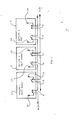
- Fig 1 is an outline block diagram of one embodiment of an apparatus according to the present invention.
- Fig 2 illustrates a further block diagram of one embodiment of an apparatus according to the present invention.
- Fig 1 illustrates a series-coupling of three boilers 1, 2 and 3. These boilers are, as regards water engineering, connected in series in such a manner that the return water from a circulation system is fed into boiler 1 and passes thence to the boiler 2 and to the boiler 3, whereafter the heated water is redischarged into the circulation system, for example a riser pipe.
- Each boiler 1-3 is provided with regulator equipment of per se conventional type for increasing and recduiing, respectively, the output of the boiler depending upon some desired quantity, for example the temperature in a premises which is heated by means of the water in the circulation system. Such a quantity may also include the temperature outdoors, wind speed and so on. Irrespective of the chosen regulating quantity or quantities, the regulating equipment in the boiler will either increase the output of the boiler or reduoe ita output.
- the switches in the boiler 1 are designated 4 and 5
- the switches in the boiler 2 are designated 6 and 7, and in the boiler 3, 8 and 9.
- the switches 4, 6 and 8 are interconnected in series and are connected to a voltage level of +12 V.
- the input terminals of the switches 4, 6 and 8 are each coupled to their respective boiler control equipment which is illustrated by means of the arrows 10, 11 and 12.
- the switches 5, 7 and 9 are also interconnected in series and are connected to a voltage level of +12 V.
- the signal input terminal of these switches 5, 6 and 9 is each coupled to its respective boiler control equipment, as illustrated by means of the arrows 13, 14 and 15.
- the thus realized series circuits may be increased or reduced to any optional degree.
- the voltage level +12 V is fed into the boiler 1 in its control equipment and represents a signal "permission to increase".
- its control equipment will throw the switch 4 into the position shown in Fig 1, whereby the voltage level +12 V or the signal "permission to increase” is fed further to the boiler 2 and thereby to its control equipment by the intermediary of the input terminal of the switch 6 or the arrow 11. Because of the voltage level +12 V, this boiler 2 will be given permission to increase output, but the voltage level +12 V is not fed further by means of the switch 6 to the boiler 3 until the boiler 2 has attained a certain high output or full output.
- the switch 6 will be made so that the boiler 3 also receives the voltage level +12 V and thereby the signal "permission to increase and can contribute to the heating output.
- the switch 8 is not made until the boiler 3 has reached a certain, high output or full output.
- the switch 5, 7 and 9 are provided and a voltage level +12 V or a signal “permission to reduce - " is passed from the boiler 3 by the intermediary of the arrow 15 and its control equipment to the arrow 14 and the control equipment of the boiler 2. Thanks to the voltage level +12 V from the switch 9 to the boiler 2 by the intermediary of the arrow 14, the boiler 2 is given permission to reduce its output.
- the voltage level +12 V or the signal "permission to reduce " is not, however, passed further from the boiler 2 by the intermediary of the switch 7 to the arrow 13 until such time as the boiler 2 has reduced its output to a desired, low level or zero output.
- the above-outlined priority function may be described such that the switches 4, 6 and 8 are made when full output is produced by their boilers, whereas the switches 5, 7 and 9 are made when their boilers produce no output.
- each control equipment unit is provided with an excess temperature sensor such that, if a boiler exceeds the preset temperature by a certain value, for example 6-7°C, the control equipment of the boiler will receive the "permission to reduce" signal.
- a certain value for example 6-7°C
- the control equipment of the boiler will receive the "permission to reduce" signal.
- all boilers in the system having excess temperature will reduce their output in parallel with one another.
- the control equipment of the overheated boiler will break the signal "permission to increase”. In'this way, it will be ensured that no subsequent boiler will compensate for the output loss by an output increase.
- Fig 2 illsutrates a similar series-connection of four boilers and, as will be apparent to the skilled reader, the switches in the different boilers are arranged in the same manner as in the embodiment according to Fig 1 and, similarly, the voltage level source is common for the generation of the two signals "permission to increase " and "permission to reduce”.
- Fig 2 further shows that the apparatus according to the present invention may be realized in an extremely simple manner by the passage of but one four conductor signal cable between the control equipment of each individual boiler.
- the switches may suitably consist of transistor switches or the like.
- the signal "permission to reduce” may be impressed on all boilers, whereas the signal “permission to increase " may be impressed only on the first boiler.
- the control equipment of such boilers is disposed to permit leapfrog increase and reduction of the output and one example of such control equipment includes fifteen steps with a step time of 10-20 seconds per step. It may thus be said that the switch for the signal "permission to reduce” is opened when the first control step is made and remains open as long as any step is made. When the boiler has reached the final step, the switch for the signal "permission to increase” is made , whereafter the boiler 2 begins stepwise to increase output and thereby its switch for the signal "permission to reduce” is opened, the entire regulation proceeding thus.
- each unit of control equipment there are also means for generating, in the event of an overload of more than, for example, 10% above a preset value, the signal "permission to reduce", and the signal “permission to increase” whereby the function will be the same as in the event of excess temperature.
Landscapes
- Engineering & Computer Science (AREA)
- Physics & Mathematics (AREA)
- Thermal Sciences (AREA)
- Chemical & Material Sciences (AREA)
- Combustion & Propulsion (AREA)
- Mechanical Engineering (AREA)
- General Engineering & Computer Science (AREA)
- General Physics & Mathematics (AREA)
- Automation & Control Theory (AREA)
- Control Of Steam Boilers And Waste-Gas Boilers (AREA)
- Peptides Or Proteins (AREA)
- Medicines Containing Material From Animals Or Micro-Organisms (AREA)
Priority Applications (1)
| Application Number | Priority Date | Filing Date | Title |
|---|---|---|---|
| AT82850215T ATE33182T1 (de) | 1982-02-22 | 1982-11-01 | Kontrollgeraet fuer mehrere kessel. |
Applications Claiming Priority (2)
| Application Number | Priority Date | Filing Date | Title |
|---|---|---|---|
| SE8201074 | 1982-02-22 | ||
| SE8201074A SE436927B (sv) | 1982-02-22 | 1982-02-22 | Anordning for styrning av ett antal vermepannor |
Publications (3)
| Publication Number | Publication Date |
|---|---|
| EP0086927A2 true EP0086927A2 (de) | 1983-08-31 |
| EP0086927A3 EP0086927A3 (en) | 1983-09-28 |
| EP0086927B1 EP0086927B1 (de) | 1988-03-23 |
Family
ID=20346070
Family Applications (1)
| Application Number | Title | Priority Date | Filing Date |
|---|---|---|---|
| EP82850215A Expired EP0086927B1 (de) | 1982-02-22 | 1982-11-01 | Kontrollgerät für mehrere Kessel |
Country Status (9)
| Country | Link |
|---|---|
| US (1) | US4534321A (de) |
| EP (1) | EP0086927B1 (de) |
| JP (1) | JPS58148302A (de) |
| AT (1) | ATE33182T1 (de) |
| CA (1) | CA1189597A (de) |
| DE (1) | DE3278271D1 (de) |
| FI (1) | FI72195C (de) |
| NO (1) | NO155465C (de) |
| SE (1) | SE436927B (de) |
Cited By (1)
| Publication number | Priority date | Publication date | Assignee | Title |
|---|---|---|---|---|
| WO1988005939A1 (en) * | 1987-01-28 | 1988-08-11 | Savile Burdett | Method of controlling a plurality of machines |
Families Citing this family (14)
| Publication number | Priority date | Publication date | Assignee | Title |
|---|---|---|---|---|
| GB2161625B (en) * | 1984-07-03 | 1987-07-22 | Allens Of Tipton Ltd | Heating system |
| US4860696A (en) * | 1986-12-08 | 1989-08-29 | Ebara Corporation | Apparatus for controlling boiler system |
| GB9122220D0 (en) * | 1991-10-19 | 1991-12-04 | Elia Paul | Hot water storage system |
| US5325822A (en) * | 1991-10-22 | 1994-07-05 | Fernandez Guillermo N | Electrtic, modular tankless fluids heater |
| JP2998573B2 (ja) * | 1994-09-02 | 2000-01-11 | 三浦工業株式会社 | 流体加熱機の台数制御方法 |
| JP2005030694A (ja) * | 2003-07-07 | 2005-02-03 | Denso Corp | 触媒反応ヒータ |
| US7735459B2 (en) * | 2006-06-23 | 2010-06-15 | Westcast, Inc. | Modular boiler control |
| JP4873548B2 (ja) * | 2006-07-27 | 2012-02-08 | 株式会社パロマ | 給湯システム |
| US7506617B2 (en) | 2007-03-09 | 2009-03-24 | Lochinvar Corporation | Control system for modulating water heater |
| JP5228700B2 (ja) * | 2008-08-25 | 2013-07-03 | 三浦工業株式会社 | 制御プログラム、制御装置及びボイラシステム |
| JP5621365B2 (ja) * | 2010-07-09 | 2014-11-12 | 三浦工業株式会社 | プログラム、制御器及びボイラシステム |
| US9234678B1 (en) * | 2011-09-27 | 2016-01-12 | Rheem Manufacturing Company | Stackable water heater apparatus |
| CA2792823C (en) | 2011-10-21 | 2019-10-15 | Cleaver-Brooks, Inc. | System and method of controlling condensing and non-condensing boiler firing rates |
| JP5534062B1 (ja) * | 2013-02-22 | 2014-06-25 | 三浦工業株式会社 | ボイラシステム |
Family Cites Families (11)
| Publication number | Priority date | Publication date | Assignee | Title |
|---|---|---|---|---|
| US2480883A (en) * | 1949-09-06 | Control system | ||
| US3428784A (en) * | 1966-10-05 | 1969-02-18 | Honeywell Inc | Modulating control apparatus |
| US3529173A (en) * | 1968-02-05 | 1970-09-15 | Weil Mclain Co Inc | Incremental modulating controller for electrical apparatus |
| US3513662A (en) * | 1968-11-12 | 1970-05-26 | Armour & Co | Feedback control system for sequencing motors |
| US3787729A (en) * | 1972-07-13 | 1974-01-22 | Cam Ind Inc | Sequencing step control |
| DE2355988C2 (de) * | 1973-11-09 | 1981-10-01 | Stiebel Eltron Gmbh & Co Kg, 3450 Holzminden | Elektrischer Durchlauferhitzer |
| DE2757276C3 (de) * | 1977-12-22 | 1981-01-22 | Beurer Gmbh & Co, 7900 Ulm | Sicherheitsschaltung für temperaturgeregelte, mit Wechselspannung betriebene elektrische Heiz- oder Wärmegeräte |
| US4252300A (en) * | 1980-02-19 | 1981-02-24 | Prab Conveyors, Inc. | Burner control system |
| US4365742A (en) * | 1980-04-14 | 1982-12-28 | Cogar George R | Heating system |
| US4324207A (en) * | 1980-07-25 | 1982-04-13 | Leuthard John E | Energy efficient water heater |
| US4368502A (en) * | 1981-05-05 | 1983-01-11 | Barber-Colman Company | Lead-lag load lockout control |
-
1982
- 1982-02-22 SE SE8201074A patent/SE436927B/sv not_active IP Right Cessation
- 1982-11-01 DE DE8282850215T patent/DE3278271D1/de not_active Expired
- 1982-11-01 AT AT82850215T patent/ATE33182T1/de active
- 1982-11-01 EP EP82850215A patent/EP0086927B1/de not_active Expired
- 1982-11-04 NO NO823662A patent/NO155465C/no unknown
- 1982-11-05 US US06/439,489 patent/US4534321A/en not_active Expired - Fee Related
- 1982-11-11 FI FI823882A patent/FI72195C/fi not_active IP Right Cessation
- 1982-11-26 JP JP57206241A patent/JPS58148302A/ja active Pending
- 1982-12-15 CA CA000417718A patent/CA1189597A/en not_active Expired
Cited By (3)
| Publication number | Priority date | Publication date | Assignee | Title |
|---|---|---|---|---|
| WO1988005939A1 (en) * | 1987-01-28 | 1988-08-11 | Savile Burdett | Method of controlling a plurality of machines |
| GB2209855A (en) * | 1987-01-28 | 1989-05-24 | Savile Burdett | Method of controlling a plurality of machines |
| GB2209855B (en) * | 1987-01-28 | 1991-07-31 | Savile Burdett | Method of controlling a plurality of machines |
Also Published As
| Publication number | Publication date |
|---|---|
| ATE33182T1 (de) | 1988-04-15 |
| NO155465B (no) | 1986-12-22 |
| US4534321A (en) | 1985-08-13 |
| EP0086927A3 (en) | 1983-09-28 |
| NO823662L (no) | 1983-08-23 |
| DE3278271D1 (en) | 1988-04-28 |
| CA1189597A (en) | 1985-06-25 |
| NO155465C (no) | 1987-04-01 |
| FI72195C (fi) | 1987-04-13 |
| EP0086927B1 (de) | 1988-03-23 |
| SE436927B (sv) | 1985-01-28 |
| FI823882L (fi) | 1983-08-23 |
| FI72195B (fi) | 1986-12-31 |
| JPS58148302A (ja) | 1983-09-03 |
| SE8201074L (sv) | 1983-08-23 |
| FI823882A0 (fi) | 1982-11-11 |
Similar Documents
| Publication | Publication Date | Title |
|---|---|---|
| US4534321A (en) | Apparatus for controlling a number of boilers | |
| EP0055315A1 (de) | Energieverteilung | |
| US4310770A (en) | Demand load control | |
| US4698738A (en) | Parallel connected power supplies having parallel connected control circuits which equalize output currents to a load even after one supply is turned off | |
| KR880002160B1 (ko) | 부하 관리 터미날 | |
| KR100330759B1 (ko) | 가압수형 원자로의 증기 발생기를 위한 전체 출력 범위에 걸친 급수 제어 | |
| US4791309A (en) | Electrical control systems | |
| US4222097A (en) | Control of high-voltage D.C. transmission systems | |
| AU601221B2 (en) | Advanced motor controller | |
| EP0098047A1 (de) | Elektrische Regelsysteme | |
| EP0160163B1 (de) | Steuersystem für eine frequenzvariable Stromversorgung | |
| JP2731331B2 (ja) | 給水ポンプ再循環流量制御装置 | |
| JPS5956827A (ja) | 自家発電装置 | |
| FR2579728B1 (fr) | Procede de transformation d'une installation de chauffage preexistante et dispositif de commande pour la mise en oeuvre du procede | |
| SE504304C2 (sv) | Anordning och förfarande för återupptagning av överförd effekt i en anläggning för överföring av högspänd likström | |
| US4691156A (en) | Variable frequency power unit controlling system | |
| RU2069437C1 (ru) | Способ послеаварийного управления перетоками мощности в энергосистеме | |
| SU1575154A1 (ru) | Устройство дл регулировани уровн в парогенераторе | |
| JPS63220002A (ja) | ボイラ自動缶数制御方法 | |
| PL311067A1 (en) | Electrical heating device, and a method of operating the same | |
| SU726619A1 (ru) | Устройство дл делени энергосистем | |
| SU1417105A1 (ru) | Устройство дл регулировани напр жени электростанции | |
| SU1277298A1 (ru) | Устройство регулировани напр жени электростанции | |
| SU1379868A1 (ru) | Устройство регулировани напр жени электростанции | |
| SU941638A1 (ru) | Система автоматического регулировани энергоблока |
Legal Events
| Date | Code | Title | Description |
|---|---|---|---|
| PUAI | Public reference made under article 153(3) epc to a published international application that has entered the european phase |
Free format text: ORIGINAL CODE: 0009012 |
|
| PUAL | Search report despatched |
Free format text: ORIGINAL CODE: 0009013 |
|
| AK | Designated contracting states |
Designated state(s): AT BE CH DE FR GB IT LI LU NL SE |
|
| AK | Designated contracting states |
Designated state(s): AT BE CH DE FR GB IT LI LU NL SE |
|
| 17P | Request for examination filed |
Effective date: 19840313 |
|
| GRAA | (expected) grant |
Free format text: ORIGINAL CODE: 0009210 |
|
| AK | Designated contracting states |
Kind code of ref document: B1 Designated state(s): AT BE CH DE FR GB IT LI LU NL SE |
|
| PG25 | Lapsed in a contracting state [announced via postgrant information from national office to epo] |
Ref country code: NL Effective date: 19880323 |
|
| REF | Corresponds to: |
Ref document number: 33182 Country of ref document: AT Date of ref document: 19880415 Kind code of ref document: T |
|
| REF | Corresponds to: |
Ref document number: 3278271 Country of ref document: DE Date of ref document: 19880428 |
|
| ITF | It: translation for a ep patent filed | ||
| ET | Fr: translation filed | ||
| NLV1 | Nl: lapsed or annulled due to failure to fulfill the requirements of art. 29p and 29m of the patents act | ||
| PG25 | Lapsed in a contracting state [announced via postgrant information from national office to epo] |
Ref country code: LU Free format text: LAPSE BECAUSE OF NON-PAYMENT OF DUE FEES Effective date: 19881130 |
|
| PLBE | No opposition filed within time limit |
Free format text: ORIGINAL CODE: 0009261 |
|
| STAA | Information on the status of an ep patent application or granted ep patent |
Free format text: STATUS: NO OPPOSITION FILED WITHIN TIME LIMIT |
|
| 26N | No opposition filed | ||
| ITTA | It: last paid annual fee | ||
| PGFP | Annual fee paid to national office [announced via postgrant information from national office to epo] |
Ref country code: GB Payment date: 19921028 Year of fee payment: 11 |
|
| PGFP | Annual fee paid to national office [announced via postgrant information from national office to epo] |
Ref country code: FR Payment date: 19921125 Year of fee payment: 11 |
|
| PGFP | Annual fee paid to national office [announced via postgrant information from national office to epo] |
Ref country code: AT Payment date: 19921127 Year of fee payment: 11 |
|
| PGFP | Annual fee paid to national office [announced via postgrant information from national office to epo] |
Ref country code: BE Payment date: 19921130 Year of fee payment: 11 |
|
| PGFP | Annual fee paid to national office [announced via postgrant information from national office to epo] |
Ref country code: DE Payment date: 19921230 Year of fee payment: 11 |
|
| PGFP | Annual fee paid to national office [announced via postgrant information from national office to epo] |
Ref country code: CH Payment date: 19930210 Year of fee payment: 11 |
|
| PG25 | Lapsed in a contracting state [announced via postgrant information from national office to epo] |
Ref country code: GB Effective date: 19931101 Ref country code: AT Effective date: 19931101 |
|
| PG25 | Lapsed in a contracting state [announced via postgrant information from national office to epo] |
Ref country code: LI Effective date: 19931130 Ref country code: CH Effective date: 19931130 Ref country code: BE Effective date: 19931130 |
|
| BERE | Be: lapsed |
Owner name: RYDBORN STEN AKE OLAUS Effective date: 19931130 |
|
| GBPC | Gb: european patent ceased through non-payment of renewal fee |
Effective date: 19931101 |
|
| PG25 | Lapsed in a contracting state [announced via postgrant information from national office to epo] |
Ref country code: FR Effective date: 19940729 |
|
| REG | Reference to a national code |
Ref country code: CH Ref legal event code: PL |
|
| PG25 | Lapsed in a contracting state [announced via postgrant information from national office to epo] |
Ref country code: DE Effective date: 19940802 |
|
| REG | Reference to a national code |
Ref country code: FR Ref legal event code: ST |
|
| EAL | Se: european patent in force in sweden |
Ref document number: 82850215.3 |
|
| PGFP | Annual fee paid to national office [announced via postgrant information from national office to epo] |
Ref country code: SE Payment date: 19951123 Year of fee payment: 14 |
|
| PG25 | Lapsed in a contracting state [announced via postgrant information from national office to epo] |
Ref country code: SE Effective date: 19961102 |
|
| EUG | Se: european patent has lapsed |
Ref document number: 82850215.3 |