EP0086962A2 - Führungseinrichtung für höhenverschiebbare Fensterscheiben - Google Patents
Führungseinrichtung für höhenverschiebbare Fensterscheiben Download PDFInfo
- Publication number
- EP0086962A2 EP0086962A2 EP83100540A EP83100540A EP0086962A2 EP 0086962 A2 EP0086962 A2 EP 0086962A2 EP 83100540 A EP83100540 A EP 83100540A EP 83100540 A EP83100540 A EP 83100540A EP 0086962 A2 EP0086962 A2 EP 0086962A2
- Authority
- EP
- European Patent Office
- Prior art keywords
- window glass
- sliding window
- sliding
- guide
- substantially equal
- Prior art date
- Legal status (The legal status is an assumption and is not a legal conclusion. Google has not performed a legal analysis and makes no representation as to the accuracy of the status listed.)
- Granted
Links
Images



Classifications
-
- B—PERFORMING OPERATIONS; TRANSPORTING
- B60—VEHICLES IN GENERAL
- B60J—WINDOWS, WINDSCREENS, NON-FIXED ROOFS, DOORS, OR SIMILAR DEVICES FOR VEHICLES; REMOVABLE EXTERNAL PROTECTIVE COVERINGS SPECIALLY ADAPTED FOR VEHICLES
- B60J1/00—Windows; Windscreens; Accessories therefor
- B60J1/08—Windows; Windscreens; Accessories therefor arranged at vehicle sides
- B60J1/12—Windows; Windscreens; Accessories therefor arranged at vehicle sides adjustable
- B60J1/16—Windows; Windscreens; Accessories therefor arranged at vehicle sides adjustable slidable
- B60J1/17—Windows; Windscreens; Accessories therefor arranged at vehicle sides adjustable slidable vertically
-
- B—PERFORMING OPERATIONS; TRANSPORTING
- B60—VEHICLES IN GENERAL
- B60J—WINDOWS, WINDSCREENS, NON-FIXED ROOFS, DOORS, OR SIMILAR DEVICES FOR VEHICLES; REMOVABLE EXTERNAL PROTECTIVE COVERINGS SPECIALLY ADAPTED FOR VEHICLES
- B60J10/00—Sealing arrangements
- B60J10/70—Sealing arrangements specially adapted for windows or windscreens
- B60J10/74—Sealing arrangements specially adapted for windows or windscreens for sliding window panes, e.g. sash guides
Definitions
- This invention relates to a guide structure for sliding window glass of an automotive door or the like, and more particularly it pertains to an improved guide structure for slidably supporting sliding window glass of a curved cross-section.
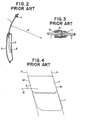
- FIG. 1 to 3 of the drawings illustrating a conventional sashed rear door of a motor vehicle, wherein sliding window glass 1 is slidably supported by means of a window regulator 3 incorporated in a door body 2.
- Guide members G are provided by which the sliding window glass 1 is slidably retained at the front and rear edges thereof.in such a manner as to be prevented from shaking when slid.
- the guide member G retaining the front edge of the sliding window glass 1 is comprised of a front leg portion 4f of an upper sash member 4 and a lower sash member 5 connected to the lower end of the front leg portion 4f.
- the other guide member G for retaining the rear edge of the sliding window glass 1 is comprised of a partition sash member 6 disposed in parallel relationship with the lower sash member 5.
- indicated at 7 is fixed window glass inserted between and retained by the partition sash member 6 and rear leg portion 4r of the upper sash member 4; shown at 10 is a glass run attached to each guide member G and slidably holding the sliding window glass 1; and denoted at 11 is a weather strip for holding the fixed window glass 7.
- the sliding window glass 1 is configured in a curved cross-sectional shape with a radius of curvature R.
- the guide members for holding the sliding window glass 1 of such a shape are also configured in.a curved cross-sectional shape having a radius of curvature equal to the radius of cruvature R of the sliding window glass 1, as shown in Figure 2.
- Some formative specifications require that the sliding window glass 1 be slidable at a predetermined angle 6, less than a right angle, with respect to a horizontal: line 8 as shown in Figures 1 and 4.
- the front and rear edges of the sliding window glass 1 are configured in the form of end faces 9f and 9r inclined relative to the horizontal line 8 with an angle equal to the aforementioned sliding inclination angle of the sliding window glass 1, and that the guide members G are disposed along straight lines lf and lr (see Figure 4) inclined with respect to the horizontal line 8.
- the structure according to the present invention is provided with sliding window glass guide members which are respectively configured in compliance with the sliding loci of the sliding window.glass. More specifically, the guide members are shaped in the form of helixes extending along a cylindrical surface of a radius of curvature equal to that of the sliding window glass and with a helical angle equal to the sliding inclination angle of the sliding window glass.
- sliding window glass guide structure according to a first embodiment of the present invention, wherein the present invention is applied to an automotive sashed rear door including sliding window glass 1 and fixed window glass 7.
- the sliding window glass 1 is configured in a curved cross-sectional shape with a predetermined radius of curvature R, and provided, at the front and rear edges thereof, with end faces 9f and 9r each of which is shaped in the form of a helix and inclined, with respect to a horizontal line 8, through an angle equal to the sliding inclination angle 6 of the sliding window glass.1.
- guide members G are provided which are adapted to slidably retain the sliding window glass 1 at the front and rear edges thereof.
- the guide members G are comprised of a front leg portion 4f of an upper sash member 4, a lower sash member 5, and a partition sash member 6, and thus similar to those of Figure 1 in this respect: In this embodiment, however, it is to be particularly noted that the guide members G are configured in compliance with the slide loci of the sliding window glass 1.
- the sliding window glass 1 is slid, along the circumferential surface of a notional cylinder 20 having a radius of curvature R, from the uppermost position abcd to the lowermost position a'b'c'd', so that the front edge ab and rear edge cd of the sliding window glass 1 are moved, along helixes Sf and Sr each having a helical angle equal to the aforementioned sliding inclination angle 6.
- the front and rear guide members G are configured in correspondence to the helixes Sf and Sr mentioned above, respectively.
- a window regulator 3 which is arranged to support the sliding window glass 1 by means of X type arms 21.
- the sliding window glass support structure it is possible to maintain a fixed relationship in relative position between the sliding window glass 1 and the guide members G when the sliding window glass 1 is slid, thus precluding the tendency that gaps occur between the sliding window glass 1 and glass runs 10 (see Figure 3) of the guide members G and/or the sliding window glass 1 bites into the glass runs 10.
- the sliding window glass 1 is positively retained by the guide members G so that the.possibility is completely precluded that the sliding window glass 1, when slid, turns out shaky and/or is hindered from the sliding movement.
- the present invention is applied to an automotive sashed front door wherein sliding window glass 1 is configured in a curved cross-sectional shape with a radius of curvature R as in the aforementioned first embodiment.
- the front edge of the sliding window glass 1 is shaped in the form of a forwardly inclined end face 9f' for the purpose of securing a side sight, while the rear edge of the sliding window glass 1 is configured in the form of an end face 9r inclined with an angle equal to the sliding inclination angle 6 of the sliding window glass 1.
- the bottom end of the front edge of the sliding window glass 1 is formed as an end face 9f which is parallel to the rear end face 9r.
- the sliding window glass 1 is slidably retained, at its front edge or end face 9f, by a guide member G which is constituted by the bottom end of a front leg portion 4f of an upper sash member 4 and a front lower sash member 5, and, at its rear edge or end face 9r, by another guide member G which comprises a rear leg portion 4r of the upper sash member 4 and a rear lower sash member 5r coupled to the bottom end .of the rear leg portion 4r.
- a guide member G which is constituted by the bottom end of a front leg portion 4f of an upper sash member 4 and a front lower sash member 5, and, at its rear edge or end face 9r, by another guide member G which comprises a rear leg portion 4r of the upper sash member 4 and a rear lower sash member 5r coupled to the bottom end .of the rear leg portion 4r.
- These guide ' members ' are similar in construction to those of the aforementioned first embodiment.
- the front leg portion 4f of the upper sash member retains the front edge of the sliding window glass 1 when the latter assumes its uppermost position, while it retains no part of the sliding window glass 1 when the latter is slid;, thus, the front leg portion 4f, except for the bottom end thereof, is configured in a rectilinear form as viewed sidewise.
- FIG. 8 and 9 there is shown the sliding window glass guide structure according to a third embodiment of the present invention, wherein the present invention is applied to an automotive sashed rear door.
- this embodiment is different from the first embodiment in that the sliding window glass 1 is provided, only at the front edge thereof, with'an end face 9f inclined through an angle equal to the sliding inclination angle 6 of the sliding window glass 1 and, at the rear edge thereof, with an end face 9r' which is non-parallel with the end face 9r of the front edge mentioned above.
- the sliding window glass 1 is slidably retained, at the front edge thereof, by a guide member G which is constituted by a front leg portion 4f of an upper sash member 4 and a lower sash member 5, and, at the rear edge thereof, by another guide member G which is formed by a guide rail provided in the door body 2 and disposed in sliding engagement with a roller 24 secured to the sliding window glass 1 at a rear portion of the bottom edge thereof.
- guide members G are similar in construction to those of the first embodiment.
- a partition sash member 6, which retains the sliding window glass 1 at the rear edge thereof, does not serve as a guide member for the sliding window glass 1, since it retains no part of the sliding window glass 1 when the latter is slid.
- a window regulator 3 which is so designed as to enable the sliding window glass 1 to be slid by means of a single arm 26.
- rollers 24f and 24r are mounted, through back plates 23f and 23r, at front and rear portions of the bottom edge of sliding window glass 1 supported by means of a window regulator 3.
- a window regulator 3 Provided in the door body 2.are guide rails 25f and 25r adapted to serve as guide members G.
- the rollers 24f and 24r are disposed in sliding engagement'with the guide rails 25f and 25r, respectively.
- the guide members G of this embodiment are similar in construction to those of the first embodiment except that the construction thereof is determined on the basis of the sliding inclination angle 6 of the sliding window glass 1, irrespective of front and rear end faces 9f and 9r of the sliding window glass 1.
- the present invention was applied to an automotive door, it is not limited thereto but equally applicable to a sliding type side window or the like.
- each of the guide members is configured in the form of a helix extending along the circumferential surface of a notional cylinder having a predetermined radius of curvature equal to the radius of curvature the sliding window glass.
Landscapes
- Engineering & Computer Science (AREA)
- Mechanical Engineering (AREA)
- Window Of Vehicle (AREA)
Applications Claiming Priority (2)
| Application Number | Priority Date | Filing Date | Title |
|---|---|---|---|
| JP57026863A JPS58146678A (ja) | 1982-02-23 | 1982-02-23 | 昇降ガラスのガイド構造 |
| JP26863/82 | 1982-02-23 |
Publications (3)
| Publication Number | Publication Date |
|---|---|
| EP0086962A2 true EP0086962A2 (de) | 1983-08-31 |
| EP0086962A3 EP0086962A3 (en) | 1984-02-22 |
| EP0086962B1 EP0086962B1 (de) | 1987-05-06 |
Family
ID=12205123
Family Applications (1)
| Application Number | Title | Priority Date | Filing Date |
|---|---|---|---|
| EP83100540A Expired EP0086962B1 (de) | 1982-02-23 | 1983-01-21 | Führungseinrichtung für höhenverschiebbare Fensterscheiben |
Country Status (3)
| Country | Link |
|---|---|
| EP (1) | EP0086962B1 (de) |
| JP (1) | JPS58146678A (de) |
| DE (1) | DE3371318D1 (de) |
Cited By (2)
| Publication number | Priority date | Publication date | Assignee | Title |
|---|---|---|---|---|
| FR2604766A1 (fr) * | 1986-10-03 | 1988-04-08 | Renault | Dispositif d'etancheite pour vitre de vehicule automobile |
| EP0326300A3 (de) * | 1988-01-25 | 1991-04-24 | Mazda Motor Corporation | Glasscheibengestaltung für ein Kraftfahrzeug |
Families Citing this family (1)
| Publication number | Priority date | Publication date | Assignee | Title |
|---|---|---|---|---|
| JPS6254011U (de) * | 1985-09-26 | 1987-04-03 |
Family Cites Families (2)
| Publication number | Priority date | Publication date | Assignee | Title |
|---|---|---|---|---|
| FR666103A (fr) * | 1927-12-30 | 1929-09-27 | Glace inclinée à coulissement ascendant et descendant | |
| US3703053A (en) * | 1971-09-17 | 1972-11-21 | Gen Motors Corp | Vehicle window installation |
-
1982
- 1982-02-23 JP JP57026863A patent/JPS58146678A/ja active Granted
-
1983
- 1983-01-21 EP EP83100540A patent/EP0086962B1/de not_active Expired
- 1983-01-21 DE DE8383100540T patent/DE3371318D1/de not_active Expired
Cited By (3)
| Publication number | Priority date | Publication date | Assignee | Title |
|---|---|---|---|---|
| FR2604766A1 (fr) * | 1986-10-03 | 1988-04-08 | Renault | Dispositif d'etancheite pour vitre de vehicule automobile |
| EP0267073A1 (de) * | 1986-10-03 | 1988-05-11 | Regie Nationale Des Usines Renault | Fensterdichtung für ein Fahrzeug |
| EP0326300A3 (de) * | 1988-01-25 | 1991-04-24 | Mazda Motor Corporation | Glasscheibengestaltung für ein Kraftfahrzeug |
Also Published As
| Publication number | Publication date |
|---|---|
| EP0086962B1 (de) | 1987-05-06 |
| DE3371318D1 (en) | 1987-06-11 |
| JPS58146678A (ja) | 1983-09-01 |
| JPS636370B2 (de) | 1988-02-09 |
| EP0086962A3 (en) | 1984-02-22 |
Similar Documents
| Publication | Publication Date | Title |
|---|---|---|
| US4432166A (en) | Trimming or sealing strips | |
| EP0158274B1 (de) | Konstruktion einer Türfensterführung bei Kraftfahrzeugen | |
| US4694611A (en) | Construction of door frame in motor vehicle | |
| JPS58189481A (ja) | 窓 | |
| GB2110281A (en) | Seal; glass run | |
| EP0086962A2 (de) | Führungseinrichtung für höhenverschiebbare Fensterscheiben | |
| US4560187A (en) | Guide rail for automatic seat belt | |
| JPS60102125U (ja) | 自動車のドア構造 | |
| US4369996A (en) | Sun visor system for trucks | |
| US4616445A (en) | Construction of door in motor vehicle | |
| JPS5934924A (ja) | スライドドア車におけるガイドレ−ルの取付構造 | |
| US2955872A (en) | Closed top construction for motor vehicle with slidable doors | |
| JPH1159171A (ja) | 自動車用窓ガラス構造 | |
| US4805958A (en) | Sunroof housing for automative vehicles | |
| JPS6020785Y2 (ja) | 自動車用ドアの窓ガラス案内装置 | |
| GB2088456A (en) | Trimming or sealing strips | |
| JPH0596962A (ja) | 燃料タンクの取付構造 | |
| GB2227041A (en) | Seal structure for a motor vehicle | |
| JPS6342018Y2 (de) | ||
| JPS58136511A (ja) | ウインドシ−ルドモ−ルの取付構造 | |
| JPS61282121A (ja) | 車両用摺動式屋根構造 | |
| JPS6033096Y2 (ja) | 自動車の吊り天井支持装置 | |
| JPH0669786B2 (ja) | フラッシュサ−フェス型グラスラン | |
| CN211335550U (zh) | 一种汽车天窗导轨 | |
| US2084269A (en) | Guiding and cushioning means for slidable window panes |
Legal Events
| Date | Code | Title | Description |
|---|---|---|---|
| PUAI | Public reference made under article 153(3) epc to a published international application that has entered the european phase |
Free format text: ORIGINAL CODE: 0009012 |
|
| 17P | Request for examination filed |
Effective date: 19830121 |
|
| AK | Designated contracting states |
Designated state(s): DE FR GB |
|
| PUAL | Search report despatched |
Free format text: ORIGINAL CODE: 0009013 |
|
| AK | Designated contracting states |
Designated state(s): DE FR GB |
|
| RAP1 | Party data changed (applicant data changed or rights of an application transferred) |
Owner name: NISSAN MOTOR CO., LTD. |
|
| GRAA | (expected) grant |
Free format text: ORIGINAL CODE: 0009210 |
|
| AK | Designated contracting states |
Kind code of ref document: B1 Designated state(s): DE FR GB |
|
| PG25 | Lapsed in a contracting state [announced via postgrant information from national office to epo] |
Ref country code: FR Free format text: THE PATENT HAS BEEN ANNULLED BY A DECISION OF A NATIONAL AUTHORITY Effective date: 19870506 |
|
| REF | Corresponds to: |
Ref document number: 3371318 Country of ref document: DE Date of ref document: 19870611 |
|
| EN | Fr: translation not filed | ||
| PLBE | No opposition filed within time limit |
Free format text: ORIGINAL CODE: 0009261 |
|
| STAA | Information on the status of an ep patent application or granted ep patent |
Free format text: STATUS: NO OPPOSITION FILED WITHIN TIME LIMIT |
|
| 26N | No opposition filed | ||
| REG | Reference to a national code |
Ref country code: GB Ref legal event code: IF02 |
|
| PGFP | Annual fee paid to national office [announced via postgrant information from national office to epo] |
Ref country code: GB Payment date: 20020123 Year of fee payment: 20 |
|
| PGFP | Annual fee paid to national office [announced via postgrant information from national office to epo] |
Ref country code: DE Payment date: 20020227 Year of fee payment: 20 |
|
| PG25 | Lapsed in a contracting state [announced via postgrant information from national office to epo] |
Ref country code: GB Free format text: LAPSE BECAUSE OF EXPIRATION OF PROTECTION Effective date: 20030120 |
|
| REG | Reference to a national code |
Ref country code: GB Ref legal event code: PE20 Effective date: 20030120 |