EP0087014B1 - Appareils et procédés de granulation centrifuge - Google Patents
Appareils et procédés de granulation centrifuge Download PDFInfo
- Publication number
- EP0087014B1 EP0087014B1 EP83100941A EP83100941A EP0087014B1 EP 0087014 B1 EP0087014 B1 EP 0087014B1 EP 83100941 A EP83100941 A EP 83100941A EP 83100941 A EP83100941 A EP 83100941A EP 0087014 B1 EP0087014 B1 EP 0087014B1
- Authority
- EP
- European Patent Office
- Prior art keywords
- rotor
- housing
- knife
- wall
- severing
- Prior art date
- Legal status (The legal status is an assumption and is not a legal conclusion. Google has not performed a legal analysis and makes no representation as to the accuracy of the status listed.)
- Expired
Links
- 238000000034 method Methods 0.000 title claims description 7
- 238000005453 pelletization Methods 0.000 title description 4
- 239000008188 pellet Substances 0.000 claims description 40
- 239000000463 material Substances 0.000 claims description 25
- 230000033001 locomotion Effects 0.000 claims description 15
- 239000007921 spray Substances 0.000 claims description 13
- 239000012815 thermoplastic material Substances 0.000 claims description 10
- 239000002826 coolant Substances 0.000 claims description 9
- 239000004033 plastic Substances 0.000 claims description 9
- 229920003023 plastic Polymers 0.000 claims description 9
- 238000001816 cooling Methods 0.000 claims description 7
- 230000002093 peripheral effect Effects 0.000 claims description 6
- 238000005520 cutting process Methods 0.000 claims description 4
- 230000005574 cross-species transmission Effects 0.000 claims description 3
- 239000007788 liquid Substances 0.000 claims description 2
- 239000012530 fluid Substances 0.000 claims 2
- 239000012768 molten material Substances 0.000 claims 1
- 238000009826 distribution Methods 0.000 description 9
- 229920000642 polymer Polymers 0.000 description 6
- 230000009969 flowable effect Effects 0.000 description 4
- 230000007246 mechanism Effects 0.000 description 4
- 230000009471 action Effects 0.000 description 3
- 238000010791 quenching Methods 0.000 description 3
- XLYOFNOQVPJJNP-UHFFFAOYSA-N water Substances O XLYOFNOQVPJJNP-UHFFFAOYSA-N 0.000 description 3
- 238000010276 construction Methods 0.000 description 2
- 230000008878 coupling Effects 0.000 description 2
- 238000010168 coupling process Methods 0.000 description 2
- 238000005859 coupling reaction Methods 0.000 description 2
- 239000002245 particle Substances 0.000 description 2
- -1 polyethylene Polymers 0.000 description 2
- 230000000171 quenching effect Effects 0.000 description 2
- 241000143637 Eleocharis confervoides Species 0.000 description 1
- 239000004698 Polyethylene Substances 0.000 description 1
- 239000004743 Polypropylene Substances 0.000 description 1
- 239000004793 Polystyrene Substances 0.000 description 1
- 229910000639 Spring steel Inorganic materials 0.000 description 1
- 239000000654 additive Substances 0.000 description 1
- 238000005054 agglomeration Methods 0.000 description 1
- 230000002776 aggregation Effects 0.000 description 1
- 238000013459 approach Methods 0.000 description 1
- 230000002902 bimodal effect Effects 0.000 description 1
- 230000008602 contraction Effects 0.000 description 1
- 238000010586 diagram Methods 0.000 description 1
- 238000005265 energy consumption Methods 0.000 description 1
- 238000001125 extrusion Methods 0.000 description 1
- 239000008187 granular material Substances 0.000 description 1
- 238000010438 heat treatment Methods 0.000 description 1
- 230000001939 inductive effect Effects 0.000 description 1
- 229920001684 low density polyethylene Polymers 0.000 description 1
- 239000004702 low-density polyethylene Substances 0.000 description 1
- 239000000155 melt Substances 0.000 description 1
- 238000012986 modification Methods 0.000 description 1
- 230000004048 modification Effects 0.000 description 1
- JTJMJGYZQZDUJJ-UHFFFAOYSA-N phencyclidine Chemical compound C1CCCCN1C1(C=2C=CC=CC=2)CCCCC1 JTJMJGYZQZDUJJ-UHFFFAOYSA-N 0.000 description 1
- 230000000704 physical effect Effects 0.000 description 1
- 229920000573 polyethylene Polymers 0.000 description 1
- 229920001155 polypropylene Polymers 0.000 description 1
- 229920002223 polystyrene Polymers 0.000 description 1
- 229920000915 polyvinyl chloride Polymers 0.000 description 1
- 239000004800 polyvinyl chloride Substances 0.000 description 1
- 239000002002 slurry Substances 0.000 description 1
- 239000003190 viscoelastic substance Substances 0.000 description 1
Images

Classifications
-
- B—PERFORMING OPERATIONS; TRANSPORTING
- B29—WORKING OF PLASTICS; WORKING OF SUBSTANCES IN A PLASTIC STATE IN GENERAL
- B29B—PREPARATION OR PRETREATMENT OF THE MATERIAL TO BE SHAPED; MAKING GRANULES OR PREFORMS; RECOVERY OF PLASTICS OR OTHER CONSTITUENTS OF WASTE MATERIAL CONTAINING PLASTICS
- B29B9/00—Making granules
-
- B—PERFORMING OPERATIONS; TRANSPORTING
- B29—WORKING OF PLASTICS; WORKING OF SUBSTANCES IN A PLASTIC STATE IN GENERAL
- B29C—SHAPING OR JOINING OF PLASTICS; SHAPING OF MATERIAL IN A PLASTIC STATE, NOT OTHERWISE PROVIDED FOR; AFTER-TREATMENT OF THE SHAPED PRODUCTS, e.g. REPAIRING
- B29C48/00—Extrusion moulding, i.e. expressing the moulding material through a die or nozzle which imparts the desired form; Apparatus therefor
- B29C48/03—Extrusion moulding, i.e. expressing the moulding material through a die or nozzle which imparts the desired form; Apparatus therefor characterised by the shape of the extruded material at extrusion
- B29C48/04—Particle-shaped
-
- B—PERFORMING OPERATIONS; TRANSPORTING
- B29—WORKING OF PLASTICS; WORKING OF SUBSTANCES IN A PLASTIC STATE IN GENERAL
- B29C—SHAPING OR JOINING OF PLASTICS; SHAPING OF MATERIAL IN A PLASTIC STATE, NOT OTHERWISE PROVIDED FOR; AFTER-TREATMENT OF THE SHAPED PRODUCTS, e.g. REPAIRING
- B29C48/00—Extrusion moulding, i.e. expressing the moulding material through a die or nozzle which imparts the desired form; Apparatus therefor
- B29C48/03—Extrusion moulding, i.e. expressing the moulding material through a die or nozzle which imparts the desired form; Apparatus therefor characterised by the shape of the extruded material at extrusion
- B29C48/05—Filamentary, e.g. strands
-
- B—PERFORMING OPERATIONS; TRANSPORTING
- B29—WORKING OF PLASTICS; WORKING OF SUBSTANCES IN A PLASTIC STATE IN GENERAL
- B29C—SHAPING OR JOINING OF PLASTICS; SHAPING OF MATERIAL IN A PLASTIC STATE, NOT OTHERWISE PROVIDED FOR; AFTER-TREATMENT OF THE SHAPED PRODUCTS, e.g. REPAIRING
- B29C48/00—Extrusion moulding, i.e. expressing the moulding material through a die or nozzle which imparts the desired form; Apparatus therefor
- B29C48/25—Component parts, details or accessories; Auxiliary operations
- B29C48/36—Means for plasticising or homogenising the moulding material or forcing it through the nozzle or die
Definitions
- the present invention relates to a pelletizer and to a method of forming pellets.
- a centrifugal plastics pelletizer of this kind is used for forming pellets of thermoplastic materials such as polystyrene, polyethylene, polyvinylchloride, and polypropylene, among others.
- the pelletizing of such materials with incorporated additives is common because the pellets may be conveniently measured, packed, shipped, stored and used by the end user.
- centrifugal extruders have been developed in which thermoplastic material in a flowable state is fed into the interior of a hollow rotor to be centrifugally expressed through orifices in the rim of the rotor (see, for example, US-A-3 358 323, 3 424 832 and 3 483 281).
- a centrifugal plastics pelletizer of tpe kind referred to in the preamble of claim 1 is known by US-A-3 266 085.
- This pelletizer using extremely high speeds of rotation results in very fine granules which are subjected to a heat treatment to cause contraction of the particles to a generally spherical form.
- US-A-3 950 120 discloses a pelletizer in which material to be pelletized is fed into the interior of a die and is forced through the radial . bores as the die is rotated by the action of the pelletizing rollers. Material forced out by the rollers is cut by a knife.
- the invention consists in the characterising features of claim 1.
- a novel method of forming pellets from molten synthetic plastic material is subject matter of claim 20.
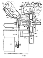
- a centrifugal pelletizer embodying the present invention includes a housing designated generally 10, within which a cooled rotor shaft 12 is rotatably supported, as by bearings 14.
- a drive motor 16 is mounted within the housing and is drivably coupled to drive rotor 12, as with a belt and pulley coupling designated generally 18.
- a hollow rotor 20 is fixedly mounted upon one end of shaft 12 to rotate with the shaft and a plurality of radially directed strand expressing orifices 22 open from the interior of the rotor through the rotor rim. In the embodiment shown in Figure 1, two rows of orifices 22 are shown.
- a hollow sleeve 24 extends axially outwardly from the rotor beyond the adjacent side wall 26 of housing 10, sleeve 24 passing freely through an opening 28 in side wall 26.
- Rotor sleeve 24 is formed with a central opening 30 through which a stationary feed tube 32 may be inserted with clearance to feed thermoplastic material at a predetermined velocity (teed rate) into the hollow interior of rotor 20 opposite a pin- like diverter and impeller 31 having a flared annular surface 31a a and a front face 31b broken by communicating slots 31c extending radially at 90° intervals to form impellers which help to accelerate the flow from the 0 r.p.m.
- thermoplastic material heated to a flowable state and fed from feed tube 32 into the interior of rotor 20, will be directed and impelled radially and then centrifugally expressed from the interior of rotor 20 through orifices 22 so that strands S ( Figures 6a and 6b) of thermoplastic material will be expressed radially outwardly from the rotor periphery.
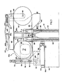
- the strands are converted into pellets by a severing device, designated generally 34 and most clearly shown in Figures 3 and 4.
- a like annularly flared surface 30a on the rotor front wall leads to the space 30 which, by permitting overflow to exit from the housing wall 26, avoids a polymer overflow buildup between the rotor and housing which would both increase power consumption and tend to cause a jam-up to occur.
- severing device 34 preferably includes two severing mechanisms designated generally 36a and 36b, which are identical except for being mirror image arrangements.
- the two mechanisms 36a and 36b are mounted upon a common carriage 38.
- Carriage 38 carries four support rollers 40 which support the carriage upon confined tracks 42a provided upon an axially extending annular shoulder 42 on housing 10 whose surface is coaxial with the rotor axis.
- a pin 44 fixedly mounted on housing 10 projects through a slot 46 in carriage 38 to define the end limits of circumferential movement of carriage 38 relative to the housing 10 which permit selective location of either severing device 36a, or severing device 36b, at a selected circumferential position relative to the rotor.
- Suitable set screw locking means 84, or the like may be employed to releasably affix carriage 38 at the selected circumferential position.
- severing devices 36a and 36b are of similar construction, thus only severing device 36a will be described in detail, it being understood the description is equally applicable to severing device 36b (primed numerals being used to designate like parts).
- Severing device 36a includes a main frame or bracket 48 upon which a pair of pulleys 50 and 52 are mounted. Pulley 50 is a driven pulley and is mounted upon the shaft 54 of a drive motor 56 whose housing is fixedly mounted upon bracket 48.
- Pulley 52 is mounted for free rotation about a pin 58 carried on the lower end of an arm 60 pivotally mounted upon bracket 48 as at 62.
- a spring tension device designated generally 64, biases arm 60 in a counterclockwise direction about pivot 62 as viewed in Figure 3 to apply tension to an endless severing band 66 (which may be constructed of thin spring steel in the range 0.1 and 0.5 mm in thickness), trained about pulleys 50 and 52.
- the device 64 includes a handle 63 pivoted at 63a and connected at 63b to an arm 63c which attaches to spring 63d, spring 63d securing at an opposite end to arm 60.
- the lower run of endless band 66 extends parallel to the axis of rotor 20 and is located to extend transversely across the path of movement of strand S expressed from the rotor orifices.
- Bracket 48 may be bodily adjusted radially of the rotor axis to vary the spacing between the rotor rim and the lower or severing run of severing band 66.
- the adjustment is accomplished by structure which includes a mounting lug 68 at the left-hand end of bracket 48 as viewed in Figure 3, which is threaded to receive an adjustment screw 70 whose lower end bears upon a pivot pin 72 mounted upon carriage 38.
- a pair of side plates 74 are pivotally mounted upon pin 72.
- Elongate slot 76 in each side plate 74 slidably receives a pair of locking screws 78 likewise threadably received in lug 68. With screws 78 loosened, rotation of screw 70 thus raises or lowers lug 68 relative to pivot 72, and the lug 68, and hence bracket 48 can be locked in a selected position of vertical adjustment by then tightening down the lock screws 78.
- the pivot 72 serves as a pivotal mounting for the entire bracket 48 so that the bracket may be pivoted in a counterclockwise direction from the position shown in Figure 3 to move severing band 66 of the severing device, clear of the path of movement of strands expressed by the rotor.
- one of the two devices 36a or 36b may be pivoted to an inoperative position so that its blade may be replaced, for example, while the other of the two severing devices is in its operative position.
- This arrangement enables blades to be replaced without requiring shutdown of the operation. Either cutter can be swung into position while the other is in operation, thereby permitting an interchange without interrupting polymer flow.
- the bracket 48 may be maintained in the operative position shown in Figure 3 by the engagement between the lower surface 80 of side plates 74 with a flat surface 82 on carriage 38. However, it may be preferable to provide further support for the cantilevered end of the bracket 48 which is swung to the operative position by means of a spring biased snap clamp device designated generally 84 ( Figure 3).
- blade guides 86 (Figure 3) are fixedly mounted on bracket 48.
- the guides 86 are formed with blade-receiving slots 88 (best seen in Figure 5) which slidably receive the blade to brace the blade against the impact it receives when it is contacted by the rapidly rotating strands and to maintain the blade against twisting.
- the guides 86 are located on opposite sides of the paths of movement of the set or sets of strands expressed from the embodiment of the rotor disclosed. In the case where rotors of greater axial thickness and greater numbers of sets of orifices are employed, additional blade guides are employed so that the unbraced portion of the blade would span no more than two sets of orifices.
- blade guides 86 on blade guide holder 86a, which may be employed to supply coolant continuously to the top of the blade (remote from the die orifices 22 so as not to chill them).
- the blade guides 86 not only commence the quenching operation with some more difficult to handle polymers (thus increasing the polymer range which can be handled), but also reduce the unsupported blade span to minimize vibration.
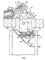
- housing 10 includes rotor housing side plates 26 and 92, which are spaced from rotor 20 with but a slight axial clearance. As best seen in Figure 2, however, the circumferential portion 94 of housing 10 is spaced a substantial distance from the periphery of rotor 20 to allow for a substantial radial growth and projection of strands from the rotor orifices and provide a chamber C between wall 94 and the rotor.
- the rotor housing is formed with an opening at 96 to permit movement of the bands 66 into and out of operative relationship with the rotor.
- a spillover housing 98 Mounted on the outer side of rotor housing side wall 26 to receive and confine thermoplastic material which may flow through the clearance between rotor sleeve 24 and feed tube 32 upon over-filling of the rotor, is a spillover housing 98.
- the sleeve 24 thus prevents any over-flow from getting into the relatively confined space between the rotor and the adjacent side wall 26 of the housing.
- the lower end of spill- over housing 98 is shown as open, but could be connected to a collection duct.
- magnetic heaters such as 100 may be mounted upon the rotor housing to function in a manner similar to that described in patent US-A-3,483,281.
- the knife 102 is in the form of a hollow housing and includes walls 102a and 102b with closed ends 102c providing a chamber 102d to which a temperature controlling liquid (normally a coolant) medium may be circulated via inlet and outlet hoses 103.
- a temperature controlling liquid normally a coolant
- Plate 102a has a trailing rear end 102e carried by an actuating handle device 103a which is manipulated to move the knife 102 to selected positions and releasably maintain them there.
- the gate 102 is pivoted to a position where it closes the entry to diverter chute 106 so no air (and therefore heat) is lost out this opening.
- gate 102 may be pivoted to an intermediate position to divert very fine hair-like plastic material (known in the trade as "angel hair”) which is in extruding operations formed and carried by the air current generated around to this point, to thus permit its removal out duct 106.
- the pin 104 which is fixed to gate 102 is journaled in a bearing 104a supported on the housing 10 and a readily releasable set or lock screw, or handle operated cam lock device, 105 can be used to secure the gate- knife 102 in selected position at or between the extreme positions illustrated in Figure 2.
- Coolant spray manifolds 110 have ports directing spray curtains C 1 and C 2 of water or another suitable medium into tube 108 (and away from rotor 20), along the false top 108a and false bottom 108b provided therein. These sprays and the resultant coolant which fills duct 108 a short distance downstream from the entrance of tube 108 quench the pellets to prevent or minimize agglomeration of the pellets.
- the air passages 108c formed between the false top 108a and the duct 108 and the false bottom 108b and the duct provide chambers for air induced into the duct by and with the coolant to disengage and flow in a reverse direction back to the mouth of duct 108. In this way additional air is prevented from being induced into the system by the air current inducing flow of the sprays C 1 and C 2 acting to pull other air into the duct 108.
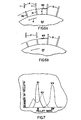
- FIGs 6a and 6b two types of cutting action of the apparatus are schematically illustrated. The different cutting actions depend primarily upon the physical properties and characteristics of the material being handled.
- FIG 6a there is shown a schematic representation of what might be termed the generalized theory of operation of the device.
- Rotor 20 is rotating in the direction indicated by arrow A, and cutter band 66 is positioned at a radial distance X from the rotor periphery.
- Cylindrical strands of thermoplastic material S expressed from the rotor orifices are carried by the rotation of rotor 20 successively into engagement with the severing blade 66 which severs a length of the material at the distal end of the strand S to form cylindrical pellets P, the severed pellets having sufficient momentum to continue to travel in straight line motion (tangentially) through the air currents in chamber C between rotor 20 and housing peripheral wall 94, on through the coolant curtain, and on into the pellet duct 108 (not shown in Figure 6a).
- the peripheral positioning of the blade severing via platform carrier 38 is also important since the exact angle of trajectory is influenced by the angle of the cutting edge.
- pellet size may be maintained substantially uniform and controlled simply by appropriately selecting the blade spacing X with respect to steady state operation of the device.
- the magnitude of the "snap-back" may be such that the strand does not grow back to its former length, during the next revolution to the severing blade.
- a smaller length of material will be cut from its distal end by the blade and the "snap- back" will not be as great as in the previous case.
- the strand will grow to a length greater than in the first case and again a longer length of strand will be severed.
- pellets of short and long lengths will alternately be severed on alternate successive revolutions of the rotor.
- Curve X2 shows the mass distribution which occurs at a slightly greater knife spacing X2 in which the phenomenon described above is evident. It will be noted that the mass distribution is much wider than in the case of knife spacing X1, and that the distribution curve has two separate peaks indicative of the severing of alternate short and long lengths from a given strand on successive revolutions because of the "snap-back" characteristic described above.
- Curve X3 represents a situation in which the length of the strand which is severed causes a "snap-back" of the unsevered portion of the strand of a magnitude such that during the completed revolution after the severing, the strand does not grow to a length sufficient to engage the severing blade at the conclusion of that revolution. At this point, the distribution becomes narrow again, but the distribution curve peaks at a pellet mass which is twice that attained for a knife spacing represented by the curve X1. In this instance, a given strand is being cut only once for each two complete revolutions of the rotor.
Landscapes
- Engineering & Computer Science (AREA)
- Mechanical Engineering (AREA)
- Processing And Handling Of Plastics And Other Materials For Molding In General (AREA)
Claims (23)
Priority Applications (1)
| Application Number | Priority Date | Filing Date | Title |
|---|---|---|---|
| AT83100941T ATE22036T1 (de) | 1982-02-16 | 1983-02-01 | Vorrichtungen und verfahren zum schleudergranulieren. |
Applications Claiming Priority (6)
| Application Number | Priority Date | Filing Date | Title |
|---|---|---|---|
| US06/348,829 US4447383A (en) | 1982-02-16 | 1982-02-16 | Method of centrifugally pelletizing certain synthetic plastic materials |
| US06/348,734 US4412964A (en) | 1982-02-16 | 1982-02-16 | Centrifugal pelletizing systems and process |
| US348734 | 1982-02-16 | ||
| US06/349,575 US4408972A (en) | 1982-02-17 | 1982-02-17 | Centrifugal pelletizers |
| US348829 | 1994-11-29 | ||
| US349575 | 1999-07-08 |
Publications (2)
| Publication Number | Publication Date |
|---|---|
| EP0087014A1 EP0087014A1 (fr) | 1983-08-31 |
| EP0087014B1 true EP0087014B1 (fr) | 1986-09-10 |
Family
ID=27407859
Family Applications (1)
| Application Number | Title | Priority Date | Filing Date |
|---|---|---|---|
| EP83100941A Expired EP0087014B1 (fr) | 1982-02-16 | 1983-02-01 | Appareils et procédés de granulation centrifuge |
Country Status (2)
| Country | Link |
|---|---|
| EP (1) | EP0087014B1 (fr) |
| DE (1) | DE3365937D1 (fr) |
Families Citing this family (5)
| Publication number | Priority date | Publication date | Assignee | Title |
|---|---|---|---|---|
| US4790736A (en) * | 1984-07-20 | 1988-12-13 | John E. Benoit | Apparatus for centrifugal fiber spinning with pressure extrusion |
| CN114801118B (zh) * | 2022-03-10 | 2024-01-26 | 广东德福生新材料科技有限公司 | 一种粉末涂料挤出冷却设备 |
| CN118849386B (zh) * | 2024-08-24 | 2025-03-11 | 江苏华财管道有限公司 | 一种塑料管道加工用冷却装置及其冷却方法 |
| CN118977342B (zh) * | 2024-10-16 | 2025-03-07 | 太和县白云塑业有限公司 | 一种可防止塑料颗粒粘结的冷却装置 |
| CN120883837B (zh) * | 2025-10-09 | 2025-12-09 | 山西农业大学 | 一种小麦秸秆粉碎还田装置 |
Family Cites Families (6)
| Publication number | Priority date | Publication date | Assignee | Title |
|---|---|---|---|---|
| US3358323A (en) * | 1963-03-25 | 1967-12-19 | Dow Chemical Co | Processing of plastic |
| US3266085A (en) * | 1964-03-20 | 1966-08-16 | Dow Chemical Co | Apparatus to manufacture particulate thermoplastic resinous material |
| US3424832A (en) * | 1967-04-10 | 1969-01-28 | Dow Chemical Co | Processing of plastic |
| US3483281A (en) * | 1967-10-27 | 1969-12-09 | Dow Chemical Co | Centrifugal extrusion employing eddy currents |
| GB1143627A (fr) * | 1973-03-27 | 1900-01-01 | ||
| GB1473830A (en) * | 1973-12-21 | 1977-05-18 | Simon Barron Ltd | Pelletising machines |
-
1983
- 1983-02-01 DE DE8383100941T patent/DE3365937D1/de not_active Expired
- 1983-02-01 EP EP83100941A patent/EP0087014B1/fr not_active Expired
Also Published As
| Publication number | Publication date |
|---|---|
| EP0087014A1 (fr) | 1983-08-31 |
| DE3365937D1 (en) | 1986-10-16 |
Similar Documents
| Publication | Publication Date | Title |
|---|---|---|
| CA1176811A (fr) | Traitement de materiaux en elastomere | |
| US4123207A (en) | Underwater pelletizer and heat exchanger die plate | |
| US20050077644A1 (en) | High pressure liquid jet cutting system and method for forming polymer pellets | |
| US4099900A (en) | Pellet cooling system | |
| US3753637A (en) | Cooled-cutter hot-die pelletizer | |
| US4021176A (en) | Cutting apparatus | |
| US4408972A (en) | Centrifugal pelletizers | |
| EP0087014B1 (fr) | Appareils et procédés de granulation centrifuge | |
| US4978288A (en) | Apparatus for use in producing pellets | |
| CN103764358A (zh) | 熔体加工装置 | |
| US4019414A (en) | Strand granulation machine | |
| US7730817B2 (en) | Apparatus for cutting ductile materials and a method of operating the apparatus | |
| US4412964A (en) | Centrifugal pelletizing systems and process | |
| US4569810A (en) | Apparatus and methods for immersed-head cutting of thermoplastics | |
| US20090050719A1 (en) | Blade granulator and method for the production of cut bodies | |
| US4447383A (en) | Method of centrifugally pelletizing certain synthetic plastic materials | |
| US3424832A (en) | Processing of plastic | |
| CA1196161A (fr) | Systemes centrifuges de pastillage | |
| CN216935918U (zh) | 一种新型干法切条造粒机 | |
| CN211807172U (zh) | 半导电屏蔽材料挤出加工设备 | |
| CN214521258U (zh) | 一种用于水下切粒机的进刀自动调节装置 | |
| JP3068023B2 (ja) | ストランドカット方法及び装置 | |
| CN102209613B (zh) | 对热塑性材料的条料进行连续铸塑和造粒的装置和方法 | |
| CN214819953U (zh) | 一种具有冷却功能的切粒装置 | |
| CN209869138U (zh) | 一种塑料粒子切割机 |
Legal Events
| Date | Code | Title | Description |
|---|---|---|---|
| PUAI | Public reference made under article 153(3) epc to a published international application that has entered the european phase |
Free format text: ORIGINAL CODE: 0009012 |
|
| AK | Designated contracting states |
Designated state(s): AT CH DE FR GB IT LI |
|
| 17P | Request for examination filed |
Effective date: 19831007 |
|
| GRAA | (expected) grant |
Free format text: ORIGINAL CODE: 0009210 |
|
| AK | Designated contracting states |
Kind code of ref document: B1 Designated state(s): AT CH DE FR GB IT LI |
|
| REF | Corresponds to: |
Ref document number: 22036 Country of ref document: AT Date of ref document: 19860915 Kind code of ref document: T |
|
| ITF | It: translation for a ep patent filed | ||
| REF | Corresponds to: |
Ref document number: 3365937 Country of ref document: DE Date of ref document: 19861016 |
|
| ET | Fr: translation filed | ||
| PLBE | No opposition filed within time limit |
Free format text: ORIGINAL CODE: 0009261 |
|
| STAA | Information on the status of an ep patent application or granted ep patent |
Free format text: STATUS: NO OPPOSITION FILED WITHIN TIME LIMIT |
|
| 26N | No opposition filed | ||
| PGFP | Annual fee paid to national office [announced via postgrant information from national office to epo] |
Ref country code: AT Payment date: 19890102 Year of fee payment: 7 |
|
| PGFP | Annual fee paid to national office [announced via postgrant information from national office to epo] |
Ref country code: FR Payment date: 19890105 Year of fee payment: 7 |
|
| PGFP | Annual fee paid to national office [announced via postgrant information from national office to epo] |
Ref country code: GB Payment date: 19890131 Year of fee payment: 7 |
|
| PGFP | Annual fee paid to national office [announced via postgrant information from national office to epo] |
Ref country code: CH Payment date: 19890207 Year of fee payment: 7 |
|
| ITTA | It: last paid annual fee | ||
| PGFP | Annual fee paid to national office [announced via postgrant information from national office to epo] |
Ref country code: DE Payment date: 19890428 Year of fee payment: 7 |
|
| PG25 | Lapsed in a contracting state [announced via postgrant information from national office to epo] |
Ref country code: GB Effective date: 19900201 Ref country code: AT Effective date: 19900201 |
|
| PG25 | Lapsed in a contracting state [announced via postgrant information from national office to epo] |
Ref country code: LI Effective date: 19900228 Ref country code: CH Effective date: 19900228 |
|
| GBPC | Gb: european patent ceased through non-payment of renewal fee | ||
| PG25 | Lapsed in a contracting state [announced via postgrant information from national office to epo] |
Ref country code: FR Effective date: 19901031 |
|
| REG | Reference to a national code |
Ref country code: CH Ref legal event code: PL |
|
| PG25 | Lapsed in a contracting state [announced via postgrant information from national office to epo] |
Ref country code: DE Effective date: 19901101 |
|
| REG | Reference to a national code |
Ref country code: FR Ref legal event code: ST |