EP0087162B1 - Klopfsteuereinrichtung und Verfahren für eine Brennkraftmaschine - Google Patents
Klopfsteuereinrichtung und Verfahren für eine Brennkraftmaschine Download PDFInfo
- Publication number
- EP0087162B1 EP0087162B1 EP83101703A EP83101703A EP0087162B1 EP 0087162 B1 EP0087162 B1 EP 0087162B1 EP 83101703 A EP83101703 A EP 83101703A EP 83101703 A EP83101703 A EP 83101703A EP 0087162 B1 EP0087162 B1 EP 0087162B1
- Authority
- EP
- European Patent Office
- Prior art keywords
- knocking
- internal combustion
- combustion engine
- retardation
- ignition point
- Prior art date
- Legal status (The legal status is an assumption and is not a legal conclusion. Google has not performed a legal analysis and makes no representation as to the accuracy of the status listed.)
- Expired
Links
- 238000000034 method Methods 0.000 title claims description 24
- 238000002485 combustion reaction Methods 0.000 title claims description 21
- 230000002401 inhibitory effect Effects 0.000 claims description 2
- 238000001914 filtration Methods 0.000 claims 5
- 238000012937 correction Methods 0.000 description 7
- 230000000873 masking effect Effects 0.000 description 7
- 230000006835 compression Effects 0.000 description 4
- 238000007906 compression Methods 0.000 description 4
- 230000010354 integration Effects 0.000 description 4
- 239000000446 fuel Substances 0.000 description 3
- 238000012545 processing Methods 0.000 description 3
- 239000000203 mixture Substances 0.000 description 2
- 230000010355 oscillation Effects 0.000 description 2
- 239000007858 starting material Substances 0.000 description 2
- 230000002159 abnormal effect Effects 0.000 description 1
- 230000032683 aging Effects 0.000 description 1
- 230000001143 conditioned effect Effects 0.000 description 1
- 239000002826 coolant Substances 0.000 description 1
- 230000001419 dependent effect Effects 0.000 description 1
- 238000011161 development Methods 0.000 description 1
- 230000018109 developmental process Effects 0.000 description 1
- 238000010586 diagram Methods 0.000 description 1
- 238000004880 explosion Methods 0.000 description 1
- 230000001788 irregular Effects 0.000 description 1
- 238000013021 overheating Methods 0.000 description 1
- 230000035939 shock Effects 0.000 description 1
Images


Classifications
-
- F—MECHANICAL ENGINEERING; LIGHTING; HEATING; WEAPONS; BLASTING
- F02—COMBUSTION ENGINES; HOT-GAS OR COMBUSTION-PRODUCT ENGINE PLANTS
- F02P—IGNITION, OTHER THAN COMPRESSION IGNITION, FOR INTERNAL-COMBUSTION ENGINES; TESTING OF IGNITION TIMING IN COMPRESSION-IGNITION ENGINES
- F02P5/00—Advancing or retarding ignition; Control therefor
- F02P5/04—Advancing or retarding ignition; Control therefor automatically, as a function of the working conditions of the engine or vehicle or of the atmospheric conditions
- F02P5/145—Advancing or retarding ignition; Control therefor automatically, as a function of the working conditions of the engine or vehicle or of the atmospheric conditions using electrical means
- F02P5/15—Digital data processing
- F02P5/152—Digital data processing dependent on pinking
- F02P5/1523—Digital data processing dependent on pinking with particular laws of return to advance, e.g. step by step, differing from the laws of retard
-
- F—MECHANICAL ENGINEERING; LIGHTING; HEATING; WEAPONS; BLASTING
- F02—COMBUSTION ENGINES; HOT-GAS OR COMBUSTION-PRODUCT ENGINE PLANTS
- F02D—CONTROLLING COMBUSTION ENGINES
- F02D35/00—Controlling engines, dependent on conditions exterior or interior to engines, not otherwise provided for
- F02D35/02—Controlling engines, dependent on conditions exterior or interior to engines, not otherwise provided for on interior conditions
- F02D35/027—Controlling engines, dependent on conditions exterior or interior to engines, not otherwise provided for on interior conditions using knock sensors
-
- Y—GENERAL TAGGING OF NEW TECHNOLOGICAL DEVELOPMENTS; GENERAL TAGGING OF CROSS-SECTIONAL TECHNOLOGIES SPANNING OVER SEVERAL SECTIONS OF THE IPC; TECHNICAL SUBJECTS COVERED BY FORMER USPC CROSS-REFERENCE ART COLLECTIONS [XRACs] AND DIGESTS
- Y02—TECHNOLOGIES OR APPLICATIONS FOR MITIGATION OR ADAPTATION AGAINST CLIMATE CHANGE
- Y02T—CLIMATE CHANGE MITIGATION TECHNOLOGIES RELATED TO TRANSPORTATION
- Y02T10/00—Road transport of goods or passengers
- Y02T10/10—Internal combustion engine [ICE] based vehicles
- Y02T10/40—Engine management systems
Definitions
- the present invention relates.to a method and apparatus for controlling knocking of an internal combustion engine according to the precharacterizing parts of the claims 1 and 11.
- Such a method and an apparatus are known from the EP-A-30 491.
- Lean gas mixture combustion has been recently practiced in order to improve fuel economy.
- an engine output is lowered.
- a compression efficiency of the engine is increased to increase an output per unit air-fuel ratio.
- knocking is likely to occur.
- the knocking of the engine degrades a drivability because of knocking noise and leads to the reduction of the engine output due to generation of an inverse torque or the engine break due to the engine overheating.
- the knocking is closely related to an ignition timing and a maximum engine output is obtained by setting the ignition timing or an ignition leading angle to a point immediately before the knocking occurs, as a nature of the engine.
- the reduction of the ignition leading angle in order to avoid the knocking leads to the reduction of the engine output and hence it is required to set the ignition timing to the point immediately before the knocking occurs.
- it is required to optimize the ignition timing in order to maintain a maximum efficiency.
- control is made to retard the ignition timing to stop the knocking if it occurs, as shown, for example, in U.S. Patent 4,002,155, U.S. Patent 4,153,020 and Japanese Patent Application Kokai (Laid-Open) No. 87308/79.
- an output signal from a knocking sensor is compared with a background level to discriminate a knocking signal if the former exceeds the background level, and the ignition timing is retarded in accordance with the knocking signal.
- the knocking sensor senses all vibrations of the engine and the knocking is discriminated when the knocking is actually not present and the ignition timing is retarded.
- the prior art knocking control apparatus cannot maintain the engine ignition timing at the optimum position.
- the prior art reference EP-A-30 491 does not disclose a protection against a background noise included in the knocking signal detected by the knock sensor but integrates this signal including background noise.
- the US ⁇ A ⁇ 4,111,035 generally discloses an engine knock signal generating apparatus with noise channel inhibiting feed-back and is especially directed to the feedback circuitry to decrease a noise reference signal being applied to a comparator during the knock-induced peaks.
- a method which solves the above object and comprising the features in the precharacterizing part of claim 1 is according to the invention characterized by the features included in the characterizing part thereof.
- An apparatus comprising the features in the precharacterizing part of claim 11 which solves the above object is according to the invention characterized by the features included in the characterizing part of claim 11.
- Fig. 1 shows one embodiment of the present invention.
- Numeral 1 denotes an engine having a combustion chamber 10 comprising a piston 2 and a cylinder block 3.
- An ignition plug 9 is arranged in the combustion chamber 10 and a knocking sensor 4 is mounted on the engine 1.
- the knocking sensor 4 is electrically connected to a knocking detector 5 which comprises a band-pass filter 11, a background level output circuit 12, a signal amplifier 13, a comparator 14 and a noise masking gate 15.
- An output from the knocking detector 5 is supplied to an electronic engine control unit which comprises an MPU, a ROM, a RAM, an I/0 and a driver PW.
- Numeral 6 denotes a rotation angle sensor which senses a rotation angle or a velocity of the engine.
- An output from the sensor 6 is supplied to the electronic engine control unit 7 as input information.
- the electronic engine control unit 7 also receives engine operation information such as an engine temperature and a starter signal.
- An ignition output signal from the electronic engine control unit 7 is supplied to the ignition plug 9 through an ignition coil 8 so that an ignition energy is supplied to the engine. While only an ignition system is illustrated in the present embodiment, it should be understood that a fuel system is also controlled by a signal from the electronic engine control unit 7.
- a pressure change causes an amplitude of an oscillation wave and it is conveyed to the knocking sensor 4.
- This oscillation wave is sensed by the knocking sensor 4, which produces a signal as shown in Fig. 2A. Since the signal of Fig. 2A includes many noises, a frequency band inherent to the knocking is discriminated by the band-pass filter 11 of the knocking detector 5.
- the frequency band is usually 6-7.5 KHz although it may slightly vary depending on type of car.
- the output from the band-pass filter 11 is averaged by the background level output circuit 12, an output of which is supplied to the comparator 14 as a reference level to detect the knocking.
- the output of the band-pass filter 11 is also amplified by the signal amplifier 13, an output of which is supplied to the comparator 14.
- the comparator 14 compares the knocking signal with the reference level as shown in Fig. 2B and produces output signals only for those knocking signal portions which exceed the reference level as shown in Fig. 2C. Those output signals are supplied to the noise masking gate 15.
- the noise masking gate 15 determines that the detected signal is not the knocking signal but a shock noise due to unevenness of a road. In this manner, an excessively large signal is eliminated from the knocking signal.
- the knocking pulses shown in Fig. 2C are counted up in the electronic engine control unit 7 as shown in Fig. 2D.
- the unit 7 has a function to reset the counter immediately after the knocking pulse count has been stored in the RAM by an interrupt signal which is a rotation angle signal, shown in Fig. 2E, supplied from the rotation angle sensor 6.
- n 2 When a knocking intensity or a retardation angle ⁇ KN which is dependent on the knocking pulse count is to be determined for a basic ignition position ⁇ (N, L) calculated based on the operation information of the internal combustion engine, the issuance of a retardation command is suppressed when the knocking pulse count is smaller than n 2 so that a dead zone which neglects the knocking is established as shown in Fig. 3.
- the value of n 2 may be selected to any desired value.
- n 2 is usually set to "1" or larger in order to eleminate a one-shot noise so that the knocking is detected only when the count is larger than n 2 .
- the rotation angle signal is fixed at a point which is 8REF in advance of a top dead center TDC, and the basic ignition point is retarded from the rotation angle position by the angle 8(N, L).
- the retardation angle 8 KN is added to the basic ignition position 8(N, L).
- the ignition position is displaced from the rotation angle position by ⁇ ig .
- the ignition timing is advanced by one step for every 40 msec at a predetermined rate, for example, 1 deg/sec, as shown in Fig. 2G. Accordingly, the advancement angle in one step is 1/25 degree.
- the signal outputted from the knocking sensor 4 show in Fig. 1 includes many external disturbances or noises.
- the noises include an ignition noise by ignition arc of the engine and a background vibration noise inherent to the engine generated by a piston and a connecting rod as shown in Fig. 4B.
- the latter noise is also generated in a compression excursion immediately before explosion.
- Relative positional relationship of those noises, the knocking point and the engine top dead center (TDC) is shown in Fig. 4C.
- the ignition noise and the background vibration noise are in a range of minus 8 b and plus 8A relative to TDC as shown in Fig. 4B, and the knocking position is in a range of 8 K following to plus 8 KR period, as is well known in the art. This positional relationship is substantially constant for the rotational speed of the engine.
- a masking transistor 11 is connected to the junction of the signal amplifier 13 and the comparator 14 of the knocking detector 5, and a rotation angle signal generated at a phase angle of 8 REF before TDC as shown in Fig. 4A is applied to the transistor 11 as a trigger signal to produce a masking signal for a period 8 w following to a 8 T period as shown in Fig. 4C so that the knocking signal is masked during that period as shown in Fig. 4D.
- the harmful external disturbance noises are blocked for the period of 8 w as shown in Fig. 4D and the comparator 14 produces the output only during the knocking period as shown in Fig. 4E.
- the ignition point is not retarded for the one-shot irregular knocking, as described above.
- the drive circuit PW of the electronic engine control unit 7 produces a control pulse when the ignition position has been rotated by an angle ⁇ T from the rise of the rotation angle signal as shown in Fig. 4C.
- This control pulse causes the flip-flop 20 to be set to turn on the transistor 11 and set the output of the amplifier 13 to a low level so that the knocking signal is masked and the counter 21 is reset.
- the AND gate 22 is conditioned and pulses which are generated at a rate of 360 pulses per revolution of the crank and sensed by the sensor 6 through the engine control unit 7 is gated through the AND gate 22. Those pulses are counted up by the counter 21.
- 4C is supplied to the register 23 from the engine control unit 7.
- the comparator 24 produces a coincidence pulse which causes the flip-flop 20 to be reset.
- the masking of the knocking signal is released and the AND gate 22 is closed so that the counter 21 stops to count up.
- the engine control unit 7 produces the next control pulse, the same operation as described above is repeated.
- a knocking control condition is checked in a step 101. Since the engine control unit 7 properly controls the ignition timing during a starter operation or when a coolant temperature is below 60°C, the knocking control which results in the retardation is not advisable. In this case, it is determined that the knocking control condition is not met.
- the process jumps to a step 112, and when the decision of the knocking condition is made, the process shifts to a step 102A.
- step 102A a value corresponding to 8 w is stored in the register 23, and in a step 102B a control pulse is generated if the rotation of angle 8 T is detected by the rotation angle signal.
- the flip-flop 20 is set to mask the knocking signal and reset the counter 21 described above.
- a step 103 the knocking count of the knocking counter 21 of the engine control unit 7 which counts the knocking signals is loaded to the RAM.
- the knocking counter 21 is reset. After the knocking counter 21 has been reset in the step 104, the count is compared with a predetermined value, that is, n 2 in Fig. 3 in a step 105. If the comparison in the step 105 shows that the count is not larger than the predetermined value n 2 , the process jumps to the step 112, and if the count is larger than the predetermined value n 2 , the process shifts to a step 106 where a proportional retardation angle corresponding to the count is looked up by a table which contains the relation as shown in Fig. 3.
- a correction limit for the knocking control quantity 8 KN is determined. Since the ignition timing is retarded incrementarily by the retardation angle corresponding to the count each time when the knocking is detected, the retardation is limited by the correction limit processing so that the unnecessarily large retardation due to misdetection of the noise as the knocking signal is prevented.
- the correction limit is determined in accordance with a map which is predetermined in accordance with an operation condition of the engine.
- the knocking control quantity 8 KN is added to the ignition timing 8(N, L) calculated based on the operation condition to produce an ignition timing 8 10 in a step 109.
- the ignition timing ⁇ ig is set in the register.
- the count N KN of the knocking counter 21 is incremented by one.
- the knocking counter 21 represents the number of times of the occurrence of knocking.
- the count N 'GN of the ignition counter is incremented by one.
- the ignition counter is incremented by one each time when the rotation angle interrupt occurs.
- the process is returned, and if the decision is YES, the process is shifted to a step 114 where the count N KN of the knocking register is stored in the RAM, and in a step 115, the knocking register is cleared and the process is returned.
- the count N KN stored in the RAM represents the frequency of the occurrence of knocking.
- the frequency of the occurrence of knocking is high, it means shortage of the retardation limit.
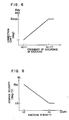
- the increment of the correction limit is fixed as shown in Fig. 6.
- an ignition task is executed.
- the ignition task is executed, and in a step 201, the ignition timing O(N, L) is computed by map look-up based on operation parameters in a well-known manner, and in a step 202 the knocking control condition is checked in the same manner as the step 101. If the knocking control condition is met in the step 202, it means that the ignition timing is retarded, and an integration quantity (advance velocity) is computed in a step 203.
- the knocking control condition is not met in the step 202, it means that the ignition timing is not retarded, and an ignition timing increment 8 KN corresponding to the knocking control quantity is set to zero in a step 204 and the process exits.
- the knocking intensity loaded in the step 103 is read out and the advance velocity is read out from a map stored in the ROM which contains a relation shown in Fig. 8. As shown in Fig. 8, the larger the knocking intensity is, the smaller is the advance velocity, and hence the lower is the frequency of the occurrence of knocking.
- the advanced velocity represents an angle or an integration quantity to be advanced in a step 205.
- the integration quantity is subtracted from ⁇ ig computed in the step 109.
- maximum advance angle processing is effected so that the knocking control quantity does not exceed a maximum advance angle limit which is looked up from the map based on the operation parameters. Then, the process exits.
- control is not influenced by the external disturbance such as noises and the performance is stable.
- the engine ignition timing can be maintained at an optimum point.
Landscapes
- Engineering & Computer Science (AREA)
- Signal Processing (AREA)
- Chemical & Material Sciences (AREA)
- Combustion & Propulsion (AREA)
- Mechanical Engineering (AREA)
- General Engineering & Computer Science (AREA)
- Electrical Control Of Ignition Timing (AREA)
- Combined Controls Of Internal Combustion Engines (AREA)
Claims (11)
Applications Claiming Priority (2)
| Application Number | Priority Date | Filing Date | Title |
|---|---|---|---|
| JP27325/82 | 1982-02-24 | ||
| JP57027325A JPS58144652A (ja) | 1982-02-24 | 1982-02-24 | ノツク制御装置 |
Publications (3)
| Publication Number | Publication Date |
|---|---|
| EP0087162A2 EP0087162A2 (de) | 1983-08-31 |
| EP0087162A3 EP0087162A3 (en) | 1984-12-05 |
| EP0087162B1 true EP0087162B1 (de) | 1989-06-14 |
Family
ID=12217918
Family Applications (1)
| Application Number | Title | Priority Date | Filing Date |
|---|---|---|---|
| EP83101703A Expired EP0087162B1 (de) | 1982-02-24 | 1983-02-22 | Klopfsteuereinrichtung und Verfahren für eine Brennkraftmaschine |
Country Status (4)
| Country | Link |
|---|---|
| US (1) | US4549514A (de) |
| EP (1) | EP0087162B1 (de) |
| JP (1) | JPS58144652A (de) |
| DE (1) | DE3380068D1 (de) |
Families Citing this family (15)
| Publication number | Priority date | Publication date | Assignee | Title |
|---|---|---|---|---|
| JPS60201072A (ja) * | 1984-03-23 | 1985-10-11 | Hitachi Ltd | 内燃機関の点火装置 |
| JPH0680301B2 (ja) | 1984-03-28 | 1994-10-12 | 株式会社日立製作所 | ノック制御方法 |
| SE442345B (sv) * | 1984-12-19 | 1985-12-16 | Saab Scania Ab | Forfarande for detektering av joniseringsstrom i en tendkrets ingaende i en forbrenningsmotors tendsystem jemte arrangemang for detektering av joniseringsstrom i en forbrenningsmotors tendsystem med minst en tendkrets |
| JPH0650099B2 (ja) * | 1984-12-28 | 1994-06-29 | 富士重工業株式会社 | 内燃機関の点火時期制御方法 |
| JPS62223439A (ja) * | 1986-03-22 | 1987-10-01 | Nissan Motor Co Ltd | 沸騰冷却式内燃機関のノツキング制御装置 |
| DE3721424C2 (de) * | 1986-07-01 | 1994-03-10 | Honda Motor Co Ltd | Vorrichtung zum Regeln des Zündzeitpunktes bei einer Brennkraftmaschine |
| US4790281A (en) * | 1986-07-22 | 1988-12-13 | Honda Giken Kogyo Kabushiki Kaisha | Method of and apparatus for controlling ignition timing in internal combustion engine |
| GB2229808A (en) * | 1989-03-08 | 1990-10-03 | Austin Rover Group | Method of controlling an internal combustion engine |
| DE4008170A1 (de) * | 1990-03-15 | 1991-09-19 | Bosch Gmbh Robert | Verfahren zur adaptiven klopfregelung einer brennkraftmaschine |
| FR2727161B1 (fr) * | 1994-11-23 | 1996-12-20 | Siemens Automotive Sa | Procede de retour a l'avance nominale, en l'absence de detection de cliquetis |
| JP4324158B2 (ja) * | 2005-12-05 | 2009-09-02 | トヨタ自動車株式会社 | 内燃機関の点火時期制御装置 |
| JP4583477B2 (ja) * | 2008-05-14 | 2010-11-17 | 三菱電機株式会社 | 内燃機関の制御装置 |
| US8286471B2 (en) | 2009-01-13 | 2012-10-16 | Ford Global Technologies, Llc | Variable displacement engine diagnostics |
| US7921709B2 (en) * | 2009-01-13 | 2011-04-12 | Ford Global Technologies, Llc | Variable displacement engine diagnostics |
| JP7287075B2 (ja) * | 2019-04-10 | 2023-06-06 | マツダ株式会社 | エンジンの制御装置 |
Citations (2)
| Publication number | Priority date | Publication date | Assignee | Title |
|---|---|---|---|---|
| US4111035A (en) * | 1977-11-07 | 1978-09-05 | General Motors Corporation | Engine knock signal generating apparatus with noise channel inhibiting feedback |
| EP0030491A1 (de) * | 1979-12-10 | 1981-06-17 | Regie Nationale Des Usines Renault | Elektronische Vorrichtung zur Korrektur des Zündverstellwinkels in Abhängigkeit des Kopfverhaltens |
Family Cites Families (10)
| Publication number | Priority date | Publication date | Assignee | Title |
|---|---|---|---|---|
| FR2337261A1 (fr) * | 1975-12-30 | 1977-07-29 | Inst Francais Du Petrole | Dispositif de reglage optimal de l'allumage d'un moteur a allumage commande en cours de fonctionnement |
| US4002155A (en) * | 1976-01-12 | 1977-01-11 | General Motors Corporation | Engine and engine spark timing control with knock limiting etc. |
| US4211194A (en) * | 1976-11-10 | 1980-07-08 | Nippon Soken, Inc. | Ignition system for internal combustion engines |
| US4153020A (en) * | 1977-07-26 | 1979-05-08 | The United States Of America As Represented By The Administrator Of The United States Environmental Protection Agency | Method and apparatus for spark control of engine knock |
| JPS5487308A (en) * | 1977-12-22 | 1979-07-11 | Nippon Denso Co Ltd | Knocking detector for internal combustion engine |
| JPS54109529A (en) * | 1978-02-15 | 1979-08-28 | Nippon Denso Co Ltd | Ignition timing controller for internal combustion engine |
| FR2426810A1 (fr) * | 1978-05-26 | 1979-12-21 | Sev Marchal | Procede et dispositif de correction d'avance a l'allumage par diminution de l'avance lors de l'apparition du cliquetis |
| US4274379A (en) * | 1978-06-13 | 1981-06-23 | Nippon Soken, Inc. | Method and system for controlling ignition timing of internal combustion engines |
| JPS54162032A (en) * | 1978-06-13 | 1979-12-22 | Nippon Soken Inc | Ignition time controlling apparatus for interval combustion engine |
| JPS5591765A (en) * | 1978-12-29 | 1980-07-11 | Toyota Motor Corp | Ignition timing control device for internal combustion engine |
-
1982
- 1982-02-24 JP JP57027325A patent/JPS58144652A/ja active Pending
-
1983
- 1983-02-22 EP EP83101703A patent/EP0087162B1/de not_active Expired
- 1983-02-22 DE DE8383101703T patent/DE3380068D1/de not_active Expired
- 1983-02-24 US US06/469,404 patent/US4549514A/en not_active Expired - Fee Related
Patent Citations (2)
| Publication number | Priority date | Publication date | Assignee | Title |
|---|---|---|---|---|
| US4111035A (en) * | 1977-11-07 | 1978-09-05 | General Motors Corporation | Engine knock signal generating apparatus with noise channel inhibiting feedback |
| EP0030491A1 (de) * | 1979-12-10 | 1981-06-17 | Regie Nationale Des Usines Renault | Elektronische Vorrichtung zur Korrektur des Zündverstellwinkels in Abhängigkeit des Kopfverhaltens |
Also Published As
| Publication number | Publication date |
|---|---|
| US4549514A (en) | 1985-10-29 |
| EP0087162A3 (en) | 1984-12-05 |
| JPS58144652A (ja) | 1983-08-29 |
| DE3380068D1 (en) | 1989-07-20 |
| EP0087162A2 (de) | 1983-08-31 |
Similar Documents
| Publication | Publication Date | Title |
|---|---|---|
| US4549514A (en) | Method and apparatus for controlling knocking of an internal combustion engine | |
| US4596217A (en) | Method and system to prevent knocking operation of an internal combustion engine | |
| JP3410294B2 (ja) | 内燃機関用ノック制御装置 | |
| US4774922A (en) | Spark ignition timing control system for spark ignition internal combustion engine with quicker advance of spark advance in transition from anti-knock mode to MBI mode control operation | |
| US4710881A (en) | Knock control apparatus for internal combustion engine | |
| US5121729A (en) | Knocking control method and apparatus for internal combustion engine | |
| US6328016B1 (en) | Knock suppression control apparatus for internal combustion engine | |
| US5190011A (en) | Knocking control method and apparatus for internal combustion engine | |
| US6311672B1 (en) | Device for controlling the knocking of an internal combustion engine | |
| US4261313A (en) | Method of and apparatus for controlling ignition timing of an internal-combustion engine | |
| US6298823B1 (en) | Knock control apparatus for internal combustion engine | |
| US4612902A (en) | Knocking control method and apparatus for internal combustion engine | |
| EP0096869B1 (de) | Verfahren und Gerät zur Steuerung eines Zündsystems | |
| US4699106A (en) | Knock control system for internal combustion engines | |
| US4290398A (en) | Ignition timing control system for internal combustion engine | |
| US6151954A (en) | Device for detecting knocking in an internal combustion engine | |
| EP0479833B1 (de) | Klopfregelung durch verminderung der einspritzungszeit | |
| EP0098584B1 (de) | Zündzeitpunktsteuerverfahren für Brennkraftmaschine | |
| US4269155A (en) | Ignition timing control system for internal combustion engines | |
| US4802455A (en) | Knocking control system and method for an internal combustion engine | |
| US4966117A (en) | System and method for controlling ignition timing for vehicular internal combustion engine | |
| US4523567A (en) | Ignition timing control system for internal-combustion engine | |
| US4426975A (en) | Ignition timing control system for internal combustion engines | |
| CA2065140C (en) | Vehicle engine ignition timing system and method with windowing knock control | |
| US4934327A (en) | Knock-suppressive spark ignition timing control system for an internal combustion engine with a variable retard limit |
Legal Events
| Date | Code | Title | Description |
|---|---|---|---|
| PUAI | Public reference made under article 153(3) epc to a published international application that has entered the european phase |
Free format text: ORIGINAL CODE: 0009012 |
|
| AK | Designated contracting states |
Designated state(s): CH DE FR GB IT LI NL SE |
|
| PUAL | Search report despatched |
Free format text: ORIGINAL CODE: 0009013 |
|
| AK | Designated contracting states |
Designated state(s): CH DE FR GB IT LI NL SE |
|
| 17P | Request for examination filed |
Effective date: 19850425 |
|
| 17Q | First examination report despatched |
Effective date: 19861215 |
|
| GRAA | (expected) grant |
Free format text: ORIGINAL CODE: 0009210 |
|
| RBV | Designated contracting states (corrected) |
Designated state(s): CH DE FR GB LI SE |
|
| AK | Designated contracting states |
Kind code of ref document: B1 Designated state(s): CH DE FR GB LI SE |
|
| REF | Corresponds to: |
Ref document number: 3380068 Country of ref document: DE Date of ref document: 19890720 |
|
| ET | Fr: translation filed | ||
| PG25 | Lapsed in a contracting state [announced via postgrant information from national office to epo] |
Ref country code: SE Effective date: 19900223 |
|
| PG25 | Lapsed in a contracting state [announced via postgrant information from national office to epo] |
Ref country code: LI Effective date: 19900228 Ref country code: CH Effective date: 19900228 |
|
| PLBE | No opposition filed within time limit |
Free format text: ORIGINAL CODE: 0009261 |
|
| STAA | Information on the status of an ep patent application or granted ep patent |
Free format text: STATUS: NO OPPOSITION FILED WITHIN TIME LIMIT |
|
| 26N | No opposition filed | ||
| PG25 | Lapsed in a contracting state [announced via postgrant information from national office to epo] |
Ref country code: FR Effective date: 19901031 |
|
| REG | Reference to a national code |
Ref country code: CH Ref legal event code: PL |
|
| REG | Reference to a national code |
Ref country code: FR Ref legal event code: ST |
|
| PGFP | Annual fee paid to national office [announced via postgrant information from national office to epo] |
Ref country code: GB Payment date: 19940211 Year of fee payment: 12 |
|
| PGFP | Annual fee paid to national office [announced via postgrant information from national office to epo] |
Ref country code: DE Payment date: 19940428 Year of fee payment: 12 |
|
| EUG | Se: european patent has lapsed |
Ref document number: 83101703.3 Effective date: 19901107 |
|
| PG25 | Lapsed in a contracting state [announced via postgrant information from national office to epo] |
Ref country code: GB Effective date: 19950222 |
|
| GBPC | Gb: european patent ceased through non-payment of renewal fee |
Effective date: 19950222 |
|
| PG25 | Lapsed in a contracting state [announced via postgrant information from national office to epo] |
Ref country code: DE Effective date: 19951101 |