EP0087355A1 - Verfahren zur Elevationsbestimmung eines Zieles von niedriger Höhe mittels eines Monopuls-Radarempfängers und Monopuls-Radarempfänger zur Durchführung eines solchen Verfahrens - Google Patents
Verfahren zur Elevationsbestimmung eines Zieles von niedriger Höhe mittels eines Monopuls-Radarempfängers und Monopuls-Radarempfänger zur Durchführung eines solchen Verfahrens Download PDFInfo
- Publication number
- EP0087355A1 EP0087355A1 EP83400300A EP83400300A EP0087355A1 EP 0087355 A1 EP0087355 A1 EP 0087355A1 EP 83400300 A EP83400300 A EP 83400300A EP 83400300 A EP83400300 A EP 83400300A EP 0087355 A1 EP0087355 A1 EP 0087355A1
- Authority
- EP
- European Patent Office
- Prior art keywords
- alpha
- antenna
- site
- sum
- radar
- Prior art date
- Legal status (The legal status is an assumption and is not a legal conclusion. Google has not performed a legal analysis and makes no representation as to the accuracy of the status listed.)
- Granted
Links
- 238000000034 method Methods 0.000 title claims abstract 6
- 238000005259 measurement Methods 0.000 title claims 2
- 230000005855 radiation Effects 0.000 claims abstract 4
- 238000010586 diagram Methods 0.000 claims abstract 3
Images
Classifications
-
- G—PHYSICS
- G01—MEASURING; TESTING
- G01S—RADIO DIRECTION-FINDING; RADIO NAVIGATION; DETERMINING DISTANCE OR VELOCITY BY USE OF RADIO WAVES; LOCATING OR PRESENCE-DETECTING BY USE OF THE REFLECTION OR RERADIATION OF RADIO WAVES; ANALOGOUS ARRANGEMENTS USING OTHER WAVES
- G01S13/00—Systems using the reflection or reradiation of radio waves, e.g. radar systems; Analogous systems using reflection or reradiation of waves whose nature or wavelength is irrelevant or unspecified
- G01S13/02—Systems using reflection of radio waves, e.g. primary radar systems; Analogous systems
- G01S13/06—Systems determining position data of a target
- G01S13/42—Simultaneous measurement of distance and other co-ordinates
- G01S13/44—Monopulse radar, i.e. simultaneous lobing
- G01S13/4418—Monopulse radar, i.e. simultaneous lobing with means for eliminating radar-dependent errors in angle measurements, e.g. multipath effects
Definitions
- the present invention relates to a method for measuring the site of a target at low altitude in a monopulse radar and to a monopulse radar receiver implementing such a method.
- the method according to the invention for measuring the site of a target moving at low altitude does not have the aforementioned drawbacks since it uses only a monopulse antenna and does not require any calibration curve related to the environment.
- the subject of the present invention is a measurement method which uses the sum and site difference diagrams of a conventional monopulse range finding radar.
- the problem to be solved is as follows: We want, from two successive pointing in site of the monopulse antenna depointed in site by an angle 0 and providing two successive measurements m l and m 2 of the complex ratio of the signal site difference signal / signal sum, calculate the site ⁇ of the target and the site ⁇ 'of its image, with the same bearing with respect to a reference such as the axis of the antenna, assuming the antenna diagrams perfectly known.
- the study is made in the absence of noise in order to arrive at a general formulation and is then completed by the study of the influence of thermal noise and diffuse reflection, as well as effect of variations, essentially of phase, of the specular reflection coefficient and of the antenna and receiver faults on the solution obtained with the simplifications mentioned above.
- the ratio z is invariant from one measure to another. Assuming that the field re-radiated by the target is the same in the direction of the radar and in the direction of its image, this ratio represents the complex specular reflection coefficient of the sea. The variations in this reflection coefficient result essentially those of the path difference between the direct and reflected rays. The speed of variation of this path difference is related to the trajectory and the speed of the target as well as to the height of the radar antenna above the sea. The study of these variations does not make the object of the invention and is not described here.
- the sum and site difference diagrams can be roughly approximated by polynomials.
- the approximation of the antenna diagrams by a polynomial can only be applied in the case of a target whose site, with respect to the horizon, is notably less than the narrow limit of validity of the linear approximation of the site difference diagram.
- the field of application is therefore limited to the vicinity of the horizon, that is to say to a region where the estimation of the site is very disturbed. If consequently one wants to have for the depointing ⁇ a range of variation sufficient to reduce the effect of the thermal noise it is necessary to extend the zone of validity of the models of diagrams of antenna and to abandon the approximation by a polynomial.
- the sum diagram S (x) can be represented by the Gaussian function where x is measured in width at 3 dB relative to the antenna axis.
- the calculation of the site ⁇ , and possibly of ⁇ ′, can be carried out by a specialized calculator or by a calculator previously existing.
- the monopulse antenna used can be mechanical scanning (such as antenna of the reflector, Cassegrain or lens type), electronic scanning or else mixed scanning.
- the monopulse site beam of this antenna can take two predetermined positions, one of the other being 0.
- the control of the two successive pointing operations is the responsibility of the usual computer-pointer.
- the two beam positions can be conveniently obtained by electronic switching between two primary monopulse sources stepped in elevation in the plane of the antenna and each corresponding to a pointing of the beam.
- the site calculator in fact receives not only the complex measurements m 1 and m 2 constituted by their real part and their imaginary part but also the models S (x) and D (x) chosen for the monopulse antenna diagrams in sum track. and on the way to site difference.
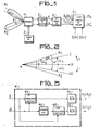
- FIG. 1 represents the block diagram of a monopulse radar receiver for measuring the site of a target at low altitude in accordance with the invention.
- the axis of the monopulse antenna 1 with electronic or mechanical scanning successively takes a first then a second direction A1 then A2 deviated by 0, the switching between these two pointing being controlled by a switching circuit 3.
- the microwave signals received by l antenna 1 pointed in the first direction A are processed in the receiver circuit 2 which delivers a signal y 1 on the sum channel ⁇ and a signal y 2 on the site difference channel ⁇ .
- These two signals feed a calculation circuit 4 delivering the digital data R 1 and l 1 corresponding respectively to the real part and to the imaginary part of the complex ratio m 1 of the signal y 2 on the site difference path ⁇ to the signal y 1 on the sum channel ⁇ .
- a detailed embodiment of the calculation circuit 4 is shown by way of nonlimiting example in FIG. 3.
- the digital data R 1 and I 1 , produced by the first calculation circuit 4 are introduced into a second calculation circuit 5 which can be specialized or use an already existing calculator (site calculator for example).
- the switch 3 then points the antenna axis in the second pointing direction A2.
- the same process is repeated and results in the development of two digital data R 2 and I 2 also corresponding to the real part and to the imaginary part respectively of the complex ratio m 2 of the signal y4 on the site difference path ⁇ to the signal y 3 on the sum channel ⁇ generated by the reception circuit 2 for the second pointing direction A2 of the monopulse antenna 1.
- FIG. 2 specifies the definition of the elevation and pointing angles of the antenna with respect to the chosen absolute reference Ax.
- This absolute reference can be the horizon for example.
- the site of the antenna axis 1 pointed in the first direction A1 is called ⁇ o .
- This known direction A1 serves as a relative reference for the sites ⁇ of the target C and ⁇ 'of its image CI calculated by the second circuit calculation 5 of Figure 1, as well as for the angle ⁇ which the antenna axis is deviated when it is switched in the direction A2.
- FIG. 3 represents a nonlimiting detailed embodiment of the first calculation circuit 4 of FIG. 1, corresponding to a reception circuit with linear processing.
- the reception circuit 2 of FIG. 1, not shown in FIG. 3, then comprises a first subset and a second subset of conventional circuits carrying out the frequency changes and the amplification which make it possible to transpose the microwave signals onto the sum channel ⁇ and on the site difference channel ⁇ respectively in intermediate frequency signals.
- the two signals channel sum ⁇ and channel difference site ⁇ at intermediate frequency thus obtained are then applied to the input of the amplitude demodulator 43 which generates a first analog signal corresponding to the real part of the ratio of the two signals.
- the sum signal and the site difference signal, out of phase of by the circuit 40, supply the amplitude demodulator 44 which generates a second analog signal corresponding to the imaginary part of the ratio of the two sum and site difference signals.
- An analog / digital converter 45 transforms the first and second analog signals respectively into digital data R1 or R2, respectively Il or 12, according to the pointing A1 or A2 of the antenna axis.
- phase processing it is also possible to use a calculation circuit 4 corresponding to a reception circuit 2 known as phase processing, which however has the drawback of introducing additional noise and of degrading the performance of the process. described.
Landscapes
- Engineering & Computer Science (AREA)
- Radar, Positioning & Navigation (AREA)
- Remote Sensing (AREA)
- Computer Networks & Wireless Communication (AREA)
- Physics & Mathematics (AREA)
- General Physics & Mathematics (AREA)
- Radar Systems Or Details Thereof (AREA)
Applications Claiming Priority (2)
| Application Number | Priority Date | Filing Date | Title |
|---|---|---|---|
| FR8202790 | 1982-02-19 | ||
| FR8202790A FR2522161A1 (fr) | 1982-02-19 | 1982-02-19 | Procede de mesure du site d'une cible a basse altitude dans un radar monopulse, dispositif mettant en oeuvre un tel procede et radar comprenant un tel dispositif |
Publications (2)
| Publication Number | Publication Date |
|---|---|
| EP0087355A1 true EP0087355A1 (de) | 1983-08-31 |
| EP0087355B1 EP0087355B1 (de) | 1987-04-22 |
Family
ID=9271169
Family Applications (1)
| Application Number | Title | Priority Date | Filing Date |
|---|---|---|---|
| EP19830400300 Expired EP0087355B1 (de) | 1982-02-19 | 1983-02-11 | Verfahren zur Elevationsbestimmung eines Zieles von niedriger Höhe mittels eines Monopuls-Radarempfängers und Monopuls-Radarempfänger zur Durchführung eines solchen Verfahrens |
Country Status (4)
| Country | Link |
|---|---|
| EP (1) | EP0087355B1 (de) |
| DE (1) | DE3371122D1 (de) |
| DK (1) | DK68783A (de) |
| FR (1) | FR2522161A1 (de) |
Cited By (4)
| Publication number | Priority date | Publication date | Assignee | Title |
|---|---|---|---|---|
| US4743907A (en) * | 1985-05-23 | 1988-05-10 | Hollandse Signaalapparaten B.V. | Radar system operating in two frequency bands |
| RU2360262C2 (ru) * | 2007-03-28 | 2009-06-27 | Владимир Иванович Винокуров | Способ измерения угловых координат протяженной цели и устройство для его осуществления |
| CN107430186A (zh) * | 2015-03-16 | 2017-12-01 | 阿瑞利斯控股有限公司 | 幅度比较单脉冲雷达系统 |
| RU2752235C1 (ru) * | 2020-09-22 | 2021-07-23 | Акционерное общество "НИИ измерительных приборов - Новосибирский завод имени Коминтерна" /АО "НПО НИИИП-НЗиК"/ | Способ измерения угла места маловысотной цели и устройство для его осуществления |
Families Citing this family (1)
| Publication number | Priority date | Publication date | Assignee | Title |
|---|---|---|---|---|
| RU2317562C2 (ru) * | 2005-06-14 | 2008-02-20 | Василий Васильевич Ефанов | Способ измерения угловых координат цели и устройство для его осуществления |
-
1982
- 1982-02-19 FR FR8202790A patent/FR2522161A1/fr active Granted
-
1983
- 1983-02-11 DE DE8383400300T patent/DE3371122D1/de not_active Expired
- 1983-02-11 EP EP19830400300 patent/EP0087355B1/de not_active Expired
- 1983-02-17 DK DK68783A patent/DK68783A/da not_active Application Discontinuation
Non-Patent Citations (3)
| Title |
|---|
| IEEE TRANSACTIONS ON AEROSPACE AND ELECTRONIC SYSTEMS, vol. AES-7, no 1, janvier 1971, pages 160-170, New York, USA * |
| IEEE TRANSACTIONS ON AEROSPACE AND ELECTRONIC SYSTEMS, vol. AES-7, no. 6, novembre 1971, pages 1123-1130, New York, USA * |
| INTERNATIONAL CONFERENCE ON RADAR PRESENT AND FUTURE, 23-25 octobre 1973, pages 160-165, Londres, GB. * |
Cited By (5)
| Publication number | Priority date | Publication date | Assignee | Title |
|---|---|---|---|---|
| US4743907A (en) * | 1985-05-23 | 1988-05-10 | Hollandse Signaalapparaten B.V. | Radar system operating in two frequency bands |
| RU2360262C2 (ru) * | 2007-03-28 | 2009-06-27 | Владимир Иванович Винокуров | Способ измерения угловых координат протяженной цели и устройство для его осуществления |
| CN107430186A (zh) * | 2015-03-16 | 2017-12-01 | 阿瑞利斯控股有限公司 | 幅度比较单脉冲雷达系统 |
| CN107430186B (zh) * | 2015-03-16 | 2021-07-20 | 阿瑞利斯控股有限公司 | 幅度比较单脉冲雷达系统 |
| RU2752235C1 (ru) * | 2020-09-22 | 2021-07-23 | Акционерное общество "НИИ измерительных приборов - Новосибирский завод имени Коминтерна" /АО "НПО НИИИП-НЗиК"/ | Способ измерения угла места маловысотной цели и устройство для его осуществления |
Also Published As
| Publication number | Publication date |
|---|---|
| DK68783A (da) | 1983-08-20 |
| FR2522161A1 (fr) | 1983-08-26 |
| FR2522161B1 (de) | 1984-04-06 |
| EP0087355B1 (de) | 1987-04-22 |
| DK68783D0 (da) | 1983-02-17 |
| DE3371122D1 (en) | 1987-05-27 |
Similar Documents
| Publication | Publication Date | Title |
|---|---|---|
| US5477230A (en) | AOA application of digital channelized IFM receiver | |
| EP0322005B1 (de) | Radioelektrischer Sensor zur Erstellung einer radioelektrischen Karte einer Landschaft | |
| EP0288374A1 (de) | Passives Telemetrie-Verfahren mittels Schall | |
| FR2648570A1 (fr) | Dispositif et procede pour mesurer l'azimut et le site d'un objet | |
| EP0143497B1 (de) | Mit stetigen frequenzmodulierten Wellen arbeitendes Monopulsradargerät mit Achsenstabilisierung | |
| Adams et al. | The imaging Doppler interferometer: Data analysis | |
| Galushko et al. | Frequency-and-angular HF sounding and ISR diagnostics of TIDs | |
| EP0872740A1 (de) | Selbsttestvorrichtung für Sender und Empfänger eines Radars insbesondere für Fahrzeuge | |
| EP0087355B1 (de) | Verfahren zur Elevationsbestimmung eines Zieles von niedriger Höhe mittels eines Monopuls-Radarempfängers und Monopuls-Radarempfänger zur Durchführung eines solchen Verfahrens | |
| FR2801682A1 (fr) | Procede de localisation d'emetteur parasite pour systeme de telecommunications par satellite | |
| Wang et al. | A CLEAN-based synthetic aperture passive localization algorithm for multiple signal sources | |
| EP1851568B1 (de) | Verfahren zur bistatischen detektion mittels passiver auswertung nicht kooperierender radioelektrischer sendungen | |
| EP0916965B1 (de) | Verfahren zur Störungsabschwächung der Reflektionsstrahlungskeulen einer Radarantenne | |
| KR970010876B1 (ko) | 다중 통로 널링을 갖는 간섭계 데이타 처리 방법 | |
| WO2005069038A1 (fr) | Dispositif d'evitement d'obstacles pour navires multicoques rapides | |
| EP1227333A1 (de) | Verfahren und Gerät zur Positionsbestimmung eines erdgebundenen Senders mittels eines Satelliten | |
| Virtanen et al. | Multipurpose incoherent scatter measurement and data analysis techniques for EISCAT3D | |
| FR2682772A1 (fr) | Procede et dispositif de mesure de courtes distances par analyse du retard de propagation d'une onde. | |
| EP1324065A1 (de) | Verfahren zur passiven Lokalisierung eines Zieles und insbesondere zur Luft-Luftlokalisierung | |
| EP0010481B1 (de) | Verfahren und Vorrichtung zum Anzeigen bewegender Ziele, insbesondere bei einem Radargerät mit variabler Wiederholungsfrequenz | |
| EP1271689A1 (de) | Verfahren zum Richten einer Gruppenantenne mit Reflektor | |
| FR3090892A1 (fr) | Procédé de mesure de distance par transformée de Fourier adaptée et système radar pour la mise en œuvre du procédé | |
| FR3116401A1 (fr) | Procédé de traitement d’un signal GNSS en vue d’atténuer au moins un signal de brouillage | |
| Knobles et al. | Broadband localization by matched fields in range and bearing in shallow water | |
| FR2725526A1 (fr) | Radar monopulse aeroporte du type air-sol |
Legal Events
| Date | Code | Title | Description |
|---|---|---|---|
| PUAI | Public reference made under article 153(3) epc to a published international application that has entered the european phase |
Free format text: ORIGINAL CODE: 0009012 |
|
| AK | Designated contracting states |
Designated state(s): DE GB IT NL |
|
| 17P | Request for examination filed |
Effective date: 19840213 |
|
| GRAA | (expected) grant |
Free format text: ORIGINAL CODE: 0009210 |
|
| AK | Designated contracting states |
Kind code of ref document: B1 Designated state(s): DE GB IT NL |
|
| ITF | It: translation for a ep patent filed | ||
| REF | Corresponds to: |
Ref document number: 3371122 Country of ref document: DE Date of ref document: 19870527 |
|
| PLBE | No opposition filed within time limit |
Free format text: ORIGINAL CODE: 0009261 |
|
| STAA | Information on the status of an ep patent application or granted ep patent |
Free format text: STATUS: NO OPPOSITION FILED WITHIN TIME LIMIT |
|
| 26N | No opposition filed | ||
| PGFP | Annual fee paid to national office [announced via postgrant information from national office to epo] |
Ref country code: DE Payment date: 19890128 Year of fee payment: 7 |
|
| PGFP | Annual fee paid to national office [announced via postgrant information from national office to epo] |
Ref country code: GB Payment date: 19890131 Year of fee payment: 7 |
|
| ITTA | It: last paid annual fee | ||
| PGFP | Annual fee paid to national office [announced via postgrant information from national office to epo] |
Ref country code: NL Payment date: 19890228 Year of fee payment: 7 |
|
| PG25 | Lapsed in a contracting state [announced via postgrant information from national office to epo] |
Ref country code: GB Effective date: 19900211 |
|
| PG25 | Lapsed in a contracting state [announced via postgrant information from national office to epo] |
Ref country code: NL Effective date: 19900901 |
|
| GBPC | Gb: european patent ceased through non-payment of renewal fee | ||
| NLV4 | Nl: lapsed or anulled due to non-payment of the annual fee | ||
| PG25 | Lapsed in a contracting state [announced via postgrant information from national office to epo] |
Ref country code: DE Effective date: 19901101 |