EP0087381B1 - Commande à sûreté intégrée avec élemént fusible - Google Patents
Commande à sûreté intégrée avec élemént fusible Download PDFInfo
- Publication number
- EP0087381B1 EP0087381B1 EP19830630021 EP83630021A EP0087381B1 EP 0087381 B1 EP0087381 B1 EP 0087381B1 EP 19830630021 EP19830630021 EP 19830630021 EP 83630021 A EP83630021 A EP 83630021A EP 0087381 B1 EP0087381 B1 EP 0087381B1
- Authority
- EP
- European Patent Office
- Prior art keywords
- actuating member
- actuator mechanism
- latch pin
- mechanism according
- fusible material
- Prior art date
- Legal status (The legal status is an assumption and is not a legal conclusion. Google has not performed a legal analysis and makes no representation as to the accuracy of the status listed.)
- Expired
Links
- 230000007246 mechanism Effects 0.000 claims description 51
- 239000000463 material Substances 0.000 claims description 41
- 238000004146 energy storage Methods 0.000 claims description 31
- 238000002844 melting Methods 0.000 claims description 18
- 230000008018 melting Effects 0.000 claims description 18
- 230000000903 blocking effect Effects 0.000 claims description 12
- 230000002093 peripheral effect Effects 0.000 claims description 7
- 230000004044 response Effects 0.000 claims description 4
- 230000000717 retained effect Effects 0.000 claims description 4
- 230000006835 compression Effects 0.000 description 5
- 238000007906 compression Methods 0.000 description 5
- 239000004215 Carbon black (E152) Substances 0.000 description 3
- 229930195733 hydrocarbon Natural products 0.000 description 3
- 150000002430 hydrocarbons Chemical class 0.000 description 3
- 238000001125 extrusion Methods 0.000 description 2
- 239000012530 fluid Substances 0.000 description 2
- 238000000034 method Methods 0.000 description 2
- 230000008569 process Effects 0.000 description 2
- 239000003795 chemical substances by application Substances 0.000 description 1
- 230000000295 complement effect Effects 0.000 description 1
- 238000013329 compounding Methods 0.000 description 1
- 230000001627 detrimental effect Effects 0.000 description 1
- 231100001261 hazardous Toxicity 0.000 description 1
- 230000013011 mating Effects 0.000 description 1
- 239000002184 metal Substances 0.000 description 1
- 230000004048 modification Effects 0.000 description 1
- 238000012986 modification Methods 0.000 description 1
- 230000000452 restraining effect Effects 0.000 description 1
Images


Classifications
-
- A—HUMAN NECESSITIES
- A62—LIFE-SAVING; FIRE-FIGHTING
- A62C—FIRE-FIGHTING
- A62C37/00—Control of fire-fighting equipment
- A62C37/08—Control of fire-fighting equipment comprising an outlet device containing a sensor, or itself being the sensor, i.e. self-contained sprinklers
- A62C37/10—Releasing means, e.g. electrically released
- A62C37/11—Releasing means, e.g. electrically released heat-sensitive
- A62C37/12—Releasing means, e.g. electrically released heat-sensitive with fusible links
-
- F—MECHANICAL ENGINEERING; LIGHTING; HEATING; WEAPONS; BLASTING
- F16—ENGINEERING ELEMENTS AND UNITS; GENERAL MEASURES FOR PRODUCING AND MAINTAINING EFFECTIVE FUNCTIONING OF MACHINES OR INSTALLATIONS; THERMAL INSULATION IN GENERAL
- F16K—VALVES; TAPS; COCKS; ACTUATING-FLOATS; DEVICES FOR VENTING OR AERATING
- F16K17/00—Safety valves; Equalising valves, e.g. pressure relief valves
- F16K17/36—Safety valves; Equalising valves, e.g. pressure relief valves actuated in consequence of extraneous circumstances, e.g. shock, change of position
- F16K17/38—Safety valves; Equalising valves, e.g. pressure relief valves actuated in consequence of extraneous circumstances, e.g. shock, change of position of excessive temperature
- F16K17/383—Safety valves; Equalising valves, e.g. pressure relief valves actuated in consequence of extraneous circumstances, e.g. shock, change of position of excessive temperature the valve comprising fusible, softening or meltable elements, e.g. used as link, blocking element, seal, closure plug
-
- Y—GENERAL TAGGING OF NEW TECHNOLOGICAL DEVELOPMENTS; GENERAL TAGGING OF CROSS-SECTIONAL TECHNOLOGIES SPANNING OVER SEVERAL SECTIONS OF THE IPC; TECHNICAL SUBJECTS COVERED BY FORMER USPC CROSS-REFERENCE ART COLLECTIONS [XRACs] AND DIGESTS
- Y10—TECHNICAL SUBJECTS COVERED BY FORMER USPC
- Y10T—TECHNICAL SUBJECTS COVERED BY FORMER US CLASSIFICATION
- Y10T137/00—Fluid handling
- Y10T137/1624—Destructible or deformable element controlled
- Y10T137/1797—Heat destructible or fusible
Definitions
- valves in a hydrocarbon process line Since the hydrocarbon media in the process line controlled by such a valve is flammable, it may be highly desirable to move the valve to a closed position in order to terminate the hydrocarbon flow in the event of a fire. In such a situation, the failure to move the valve may result in feeding the fire and compounding any resulting dangers and damages.
- the line may contain a fire extinguishing agent, the flow of which would be highly desirable under fire conditions.
- the preferred position for a valve controlling such a media would be in an open position, a position which would allow discharge of the fire repellant and serve to extinguish the fire.
- valve actuating mechanisms and controls therefore.
- the valve may be manually operated and inaccessible in case of fire. Consequently, it is possible that a particular valve or other type of mechanism will be in an undesirable position in a fire situation and an operator will be unable to control the valve to move it to the more desirable position.
- Actuator mechanisms of the type described above that will move a controlled member to a predetermined position in response to high temperature conditions are already known as described for example in US-A-4 275 754 and DE-A-24 49 678.
- These known actuator mechanisms each have a pivotable blocking lever adapted to be retained by a fusible link in a blocking position.
- a projection of the blocking lever cooperates with a stop arm of the actuator member to retain the actuator in the blocked position.
- the energy storage device must first by tensioned moving the actuator member and controlled member away from the predetermined position, thereafter the pivotable blocking lever can be fixed in its blocking position by applying the fusible link, and then the actuator member may be allowed to engage the blocking lever.
- Locking means may be used to retain the energy storage device until the fusible link has been applied, but such locking means are detrimental to the fail-safe feature of the mechanism because they may inadvertently remain engaged after applying of the fusible link.
- the actuator mechanism is characterized in that the latch means comprises a latch pin and resilient biasing means urging the latch pin radially outwardly into an extended position with respect to the actuating member, and that with the fusible material in the unmelted condition retaining the bearing member in the blocking position, the actuating member is movable from the predetermined position toward the blocked position, during such movement the latch pin being first cammed back against the resilient biasing means by engagement of a surface portion of the latch pin with the bearing member and then again being extended by the biasing means into the extended position to permit engagement between another surface portion of the latch pin and the bearing member so as to prevent return movement of the actuating member to the predetermined position.
- the fusible material can be installed with the energy storage device unloaded and only thereafter the controlled member is moved, by tensioning the energy storage, into the blocked position, with the fusible material already in the device.
- the bearing member may include a piston cylinder arrangement with the fusible material being disposed within the cylinder to limit movement of the piston within the cylinder under predetermined temperature conditions.
- the fusible material is meltable under certain other temperature conditions to allow movement of the piston within the cylinder.
- the actuating member may be rotatably movable with respect to the bearing member.
- the actuating member may include a cylindrically shaped portion with a peripheral surface and the latch pin is resiliently biased radially beyond the peripheral surface.
- Yet another aspect of the actuator mechanism may include a stop arm extending radially outward from the cylindrically shaped portion of the actuating member with the stop arm being selectively engageable with the stop member for limiting movement of the actuating member after the fusible material is in a melted condition.
- the stop member may be adjustable to vary the limiting position of the stop arm.
- means may be provided for selectively locking the actuating member in the predetermined position which corresponds to the actuating member's engagement with the stop member.
- the locking means may include a recess in the actuating member and a cooperating locking pin which is selectively insertable into the recess to limit rotation of the actuating member.
- the locking pin may be spring biased against the peripheral surface of the cylindrically shaped portion of the actuating member so as to move into the recess when the recess and locking pin are brought into registry.
- the latch pin may be reciprocally movable within a bore, the bore extending radially into the cylindrical portion of the actuating member.
- the latch pin may have a lead in angle on its end portion with the end portion being obliquely oriented with respect to the piston when the actuating member is engaged with the bearing member.
- a piston rod may be affixed to the piston with the piston rod being positioned in the rotational path of the latch pin when the fusible material is in the unmelted condition and the piston rod being movable out of the latch pin's rotational path after melting of the fusible material.
- the latch pin may have a shoulder on one of the sides, which shoulder is adapted to engage the piston rod.
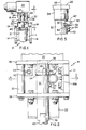
- Fig. 1 shows a plug valve generally designated by the numeral 10 which includes a body 11 with a tapered cylindrical bore portion 12 positioned between a pair of flanges 14 and 16.
- Flanges-14 and 16 are adapted, as is usual in the art, for mating with complimentary flanges (not shown) of pipe sections.
- the actuator mechanism 18 supports an energy storage device 20, which device 20 is in operative relationship with the valve 10 through the actuator mechanism 18.
- the energy storage device 20 may be one of several various types which are known, or will be known, to those skilled in the art.
- the energy storage device takes the form of a commercially available cam spring return actuator sold by Matryx Company of Cincinnati, Ohio, U.S.A.
- such a spring return actuator is described in US-A-4,248,104.
- Fig. 2 shows the actuator mechanism 18 of the present invention in greater detail. It is seen that the actuator mechanism 18 includes a base 21 which is supported by a bracket 22. The bracket 22 is in turn secured to the top of the valve body 11 through the agency of a plurality of bolts 24.
- the base 21 includes upper and lower support plates 26 and 28 respectively which are joined together by a plurality of columnar members 30.
- a compensator module which, in the illustrated embodiment takes the form of rod section 32.
- this rod section 32 is an actuating member.
- This rod section 32 is generally cylindrical in shape with female openings on its top and bottom end sections 34 and 36 respectively.
- Top end section 34 is coupled with an output shaft 38 extending downwardly from the energy storage device 20.
- the output shaft 38 has a complimentary male end section to couple with the female end section 34 of the compensator module 32.
- the opposite end section 36 of the rod section 32 is coupled with a controlled shaft 40 extending out of the valve body 11, the shaft 40 having a complimentary male end section to join with end section 36 of the compensator module 32.
- the shaft 40 extends from a tapered cylindrically shaped plug member (not shown) rotatably fitted within the correspondingly tapered portion 12 of the valve body 10.
- the plug member has a through passage (not shown) which is brought in and out of registry with the inlet and outlet of the valve body 11 in accordance with the angular position of the plug member relative to the valve body 11 to control flow through the valve 10.
- the controlled shaft 40 is intricately connected to the plug member so that rotation of the controlled shaft 40 effectuates rotation of the plug member.
- the valve 10 will have a preferred position (open or closed) in the event of a fire.
- the valve 10 forms no part of the invention, per se, and only exemplary of many devices that might be controlled by the present invention, the valve 10 will be referred to as a controlled member.
- compensator module 32 has a spring biased latch pin 42 which is reciprocally movable within a radially extending bore 44 of the rod section 32.
- This latch pin 42 is biased radially outward by a compression spring -46 fitted within the bore 44 and interposed between the inwardly disposed end 48 of the latch pin 42 and a closed end 50 of the bore 44.
- a bar member 52 is exteriorly secured to the rod section 32 by a pair of screws 54 which are threadably received by the rod section 32.
- the bar member 52 is shown extending longitudinally along the rod section 32 in a direction generally parallel to the rod section's rotational axis 56.
- the bar member 52 has an end section 58 which intrudes upon the latch pin's (42) range of movement by extending partially over the bore 48 to engage a shoulder 60 on the latch pin 42.
- the shoulder 60 is located inwardly of the latch pin's radially outermost portion 62.
- the intrusion of the end section 58 of the bar member 52 over the bore is necessarily limited and must permit some radial extension of the latch pin's (42) radially outermost portion 62.
- a fusible link module 64 which serves as a bearing member is also secured to the base 21.
- the link module 64 includes a holder arrangement, which in the preferred embodiment includes a cylinder 66 affixed to a support plate 30a extending between the columnar members 30.
- the cylinder 66 is supported by a horizontal support 66a (Fig. 2) and a connecting flange 66b, the connecting flange being held to the support plate 30a by a plurality of bolts 67.
- the cylinder 66 of the illustrated embodiment has a removable end cap 60a (Fig. 3) securely connected to the cylinder 66 upon its end most distal to the'rod section 32. While it is desirable to have one of the end caps removable, the removable end cap may be at either end.
- the end of the cylinder 66 most proximal to the rod section 32 has an aperture 70 adapted to accommodate a piston rod 72 of a piston 74.
- the piston 74 is adapted for reciprocal movement within the cylinder 66 but is normally restrained in this movement by a fusible material 76 disposed within the cylinder and having a melting temperature which is substantially less than the melting temperature of the rod section 32 or the other components of the actuator mechanism 18.
- the disposition of this fusible material 7.6 in the cylinder 66 positions the piston 74 in contacting relationship with the apertured end wall and positions the piston rod 72 in the' rotational path of latch pin 62 as that latch pin 62 is urged counterclockwise (as viewed in Fig. 3) by the energy storage device 20 with respect to the support plate 26.
- the piston rod 72 when the fusible material 76 is disposed within the cylinder 66, the piston rod 72 will provide a bearing surface for latch pin 42 and the engagement of this latch pin 42 with the piston rod 72 will limit counterclockwise (as viewed in Fig 3) movement of the rod section 32 with respect to the support plate 26.
- the energy storage device 20 normally urges the compensator module 32 in a counterclockwise direction as viewed in Fig. 3.
- engagement of the latch pin 42 with the piston rod 72 prevents that counterclockwise movement so long as the fusible material 76 occupies the cylinder 66.
- the fusible material is, however, selected as one which has a melting temperature slightly below the temperature which would indicate a danger level sufficient to move the valve 10 to its fail-safe position.
- the fusible material is CERROBASE 5550-1 and is designed to melt under fire conditions.
- the fusible material 76 of the preferred embodiment When the fusible material 76 of the preferred embodiment is exposed to a fire or other ultra-high temperature conditions sufficient to cause its melting, the pressure exerted on the fusible material by the stored energy device 20 by way of . the latch pin 42 and piston rod 72, will force extrusion of the fusible material out of holes 80 provided in the cylinder 66 (see Fig. 3a). This extrusion of fusible material 76 out of the cylinder 66 will enable the piston 74 to be moved within the cylinder 66, which will, in turn, move the piston rod 72 out of the rotational path of the latch pin 42. When the piston rod 72 is so moved from the latch pin's (42) rotational path, the compensator module 32 rotates in a counterclockwise (as viewed in Fig.
- Fig. 3 shows the illustrated actuator prior to melting of the fusible material 76 whereas Fig. 4 shows the same actuator after melting of the fusible material 76 with the compensator module 32 rotated approximately 90° from the position illustrated in Fig. 3.
- Figs. 3 and 4 also show that the rod section 32 has a radially inward extending cylindrically truncated recess 90, which in the illustrated embodiment is circumferentially disposed approximately 180° from and in radial alignment with the bore 44.
- This recess 90 accommodates the end of a locking latch or plunger pin 92, which locking latch 92 is spring biased against the peripheral surface of the rod section 32 toward the axis 56.
- the locking latch 92 is fitted within a lock block module 94 fixedly secured to the base 21.
- the locking latch 92 is reciprocally movable with respect to the lock block module 94 to selectively permit movement of the locking latch 92 into the recess 90 when these two elements 90 and 92 are in registry.
- the outwardly extending end 96 of the locking latch 94 has a truncated cylindrical configuration similar to that of the recess 90 so that the end will fit within the recess 90 when properly aligned.
- the locking latch 92 is radially aligned with respect to the rod section 32 and is urged toward the rotational axis 56 of that rod section 32 by a compression spring 98, the compression spring 98 being interposed between the locking latch 92 and a removable back plate 100 of the lock block module 94.
- This spring 98 is preferably formed of a suitable high temperature material to limit the affects of high temperature and creep.
- the lock block module 94 of the preferred embodiment has an aperture 102 opposite the back plate 100 and coaxial with the bore 93.
- This aperture 102 has a diametral dimension less than that of bore 93.
- the plunger 92 has a main body portion 104 and a retaining flange portion 106 with the main body portion 104 being disposed between the truncated end portion 96 and the retaining flange 106.
- the diameter of the main body portion 104 is slightly less than that of the diameter of the aperture 102 so as to permit reciprocal axial movement of that portion 104 in the aperture.
- the diameter of the retaining flange 106 is slightly less than the diameter of bore 93 to permit reciprocal axial movement of the flange 106 within the bore 93.
- the diameter of the end flange 106 is, however, substantially larger than that of the aperture 102.
- the flange 106 limits the axial movement of the latch pin 92 toward the radial center of rod section 32.
- An axial extension 92a of the plunger 92 extends radially away from the axis of rod section 32 through an aperture 100a of the back plate 100.
- This plunger extension 92a has a threaded end 92b distal to the retaining flange 106.
- a handle 99 is threadably secured on this threaded end 92b.
- Retaining nuts 95 and 97 are also disposed on the threaded end 92b on opposite sides of the handle 99. These retaining nuts 95 and 97 tighten against the handle 99 to prevent axial movement of that handle with respect to the plunger extension 92a.
- the back plate 100 is securely but removably fixed to the remainder of the lock block module through the agency of a plurality of screws 108, (Fig. 4).
- the removability of the back plate 100 permits easy assembly of both the latch pin 92 and the biasing spring 98 within the bore 93.
- the depicted actuator is arranged to bring the recess 90 into registry with the latch pin 92 whenever the stop bar arm 80 engages the adjustable stop 84.
- the stop 84 includes a main body portion 110 with an internally disposed threaded bore 112.
- a matingly threaded stop member 114 is axially movable within the main body portion 110. Rotation of the stop member 114 with respect to the main body portion 110 allows for fine adjustability of the stop 114. This fine adjustability of the stop member 114 is important in many applications, as for example, when the controlled member must be stopped within a precise position in order to insure sealability of the controlled device.
- An example of a controlled device which must be stopped within a precise position is a high performance butterfly valve.
- the compensator module 32 When the actuator 18 is initially moved to its normal operating position (the position depicted in Fig. 3), the compensator module 32 is moved clockwise from some position between that illustrated in Figs. 3 and 4 to first engage an inclined surface 116 of the latch pin 42 with an interior corner 118 of the piston rod 72.
- This inclined surface 116 provides a lead angle, and when further clockwise rotation of the rod section 32 is effectuated, spring 46 is compressed and the latch pin 42 is moved radially inward with respect to the rod section 32.
- the opposite corner of the latch pin 42 includes a shoulder 120.
- Fig. 3 represents the normal operating position of the actuator.
- the actuator maintains its normal operating position until subjected to fire or other ultra-high temperature conditions that will cause melting of the fusible material 76.
- the piston 74 is moved to a position corresponding to that depicted in Fig. 4, and the rod section 32 is freed for movement to its fail-safe position (Fig. 4), a position into which it is positively locked by locking pin 92.
- This positive locking of the rod section 32 prevents it from drifting away from the fail-safe position due to reverse or forward pressurization in the pipe section, thermal expansion of fluid in the pipe, or for some other reason.
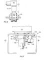
- This second preferred embodiment includes an actuator generally designated by the numeral 150 which is interposed between an energy storage device 152 and a controlled mechanism illustrated as a butterfly valve 154.
- the energy storage device 152 is a cam spring return actuator identical to the energy storage device 20 in Fig. 1.
- the actuator 150 is depicted in greater detail in Fig. 7 wherein it is seen that the actuator 150 includes a base 155 (Fig. 8) in the form of a rigid C-shaped metal housing member. This base 155 supports the energy storage device 152 and receives an output shaft 156 of that energy storage device 152. This output shaft 156 extends downwardly from the energy storage device 152 through an aperture (not shown) in the top of base 155.
- a compensator module 158 is rotatably journaled within the base 155 and has female end sections on its ends. One of the female end sections couples with a complementary male end section of the output shaft 156 while the female end section on the opposite end couples with a similar couplementary male end section of a shaft 159 of the butterfly valve 154 see Fig. 7.
- the shaft 159 of the butterfly valve 154 is connected to a disc member (not shown), the disc member being rotated in accordance with rotation of the shaft 159 to selectively block fluid flow through the valve 154. Since butterfly valves are well known in the art and form no part, per se, of the present invention, a detailed description thereof will be omitted in the interest of brevity.
- the compensator module 158 like that of the first embodiment, is a generally cylindrically shaped rod member with a spring biased latch pin 160 reciprocally movable within a closed end bore 162.
- the closed end bore 162 extends radially inward into the compensator module 158.
- the latch pin 160 is urged radially outward of the module 158 by a compression spring 164 interposed between the radially inward end of the latch pin 160 and the closed end of the bore 162.
- a cylinder 168 which has a reciprocally movable piston 166 disposed therein.
- the cylinder 168 is secured to the base 155 by having a vertically extending support 170a (Fig. 7) and a horizontally oriented connecting flange 170b.
- the connecting flange is secured to the top of the bore 155 by a plurality of bolts 172 (Fig. 3).
- a fusible material 174 fills the cylinder 168 in the Fig. 8 embodiment and precludes movement of the piston 166 into the cylinder 168 when that material 174 is below a predetermined temperature.
- a piston rod 176 extends from the piston 166.
- piston rod 176 When the fusible material 174 fills the cylinder 168, piston rod 176 is positioned in a circumferential path of the latch pin 160. The latch pin 160 is urged into engagement with the piston rod 176 by the biasing force of the energy storage device 152.
- the fusible material 174 is selected as one that will melt when subjected to fire conditions. Like the first disclosed embodiment, melting of the fusible material 174will permitthe biasing force of the energy storage device 152 to urge the piston rod 176 and piston 166 into the cylinder 168. This movement removes the piston rod 176 out of the circumferential path of the latch pin 160 and permits the compensator module 158 to rotate approximately 90° in a counterclockwise direction (as viewed from Fig. 8) until a stop arm 178, rigidly attached to the compensator module, is engaged by a movable stop 180.
- the movable stop 180 is a threaded member which is axially movable within a body 182.
- the body 182 has a threaded bore which accommodates the movable stop member 180 and permits fine axial adjustment of the stop position.
- the 90° rotation of the compensator module in which the stop arm 178 is engaged with the movable stop 180 is shown in Fig. 9.
- a lock module 184 is also secured to the base 155 and includes a spring biased locking pin 186 which is constantly urged against the circumferential surface of the compensator module 158.
- a recess 188 in the compensator module 158 is brought into registry with the locking pin 186.
- the cross sectional configuration of the recess 188 is similar to that of the latch pin 186 and designed to accommodate that latch pin.
- a compression spring 190 disposed within a bore 192 of the lock module 184 constantly urges the locking pin 186 against the circumferential surface of the compensator module 158 and pushes that locking pin 186 into the recess 188 when the locking pin 186 and recess 188 are aligned. Such an alignment is depicted in Fig. 9 wherein the locking pin 186 extends into the recess 188 to prevent further rotational movement of that compensator mechanism.
- the latch pin 160 has an obliquely oriented end surface 196 which provides a lead-in angle when the latch pin is initially brought into contact with the piston rod 176 for setting.
- the fusible material 174 fills the cylinder 168 and the piston rod 176 will have an extension corresponding to that depicted in Fig. 8.
- the compensator module 158 is rotated clockwise (as viewed in Fig. 8 and 9)
- the obliquely oriented surface 196 will engage the piston rod 176 and force radial inward movement of the latch pin 160 overcoming the bias of spring 164.
- the spring 164 urges the latch pin 160 radially outward to engage a shoulder 200 of the latch pin 160 with the piston rod 176.
- This position is depicted in Fig. 8. It is seen that the cylinder piston arrangement (166, 168) of Figs. 8 and 9 has different orientation to the compensator module 158 than that of the first illustrated embodiment. Many other variations on this arrangement will be apparent to those skilled in the art. Further, it will be apparent that the magnitude of rotation of the compensator module 158 may be readily modified by adjusting the position of the stop 182 and the lock module 184.
Landscapes
- Engineering & Computer Science (AREA)
- General Engineering & Computer Science (AREA)
- Health & Medical Sciences (AREA)
- Public Health (AREA)
- Business, Economics & Management (AREA)
- Emergency Management (AREA)
- Mechanical Engineering (AREA)
- Safety Valves (AREA)
- Fire-Extinguishing By Fire Departments, And Fire-Extinguishing Equipment And Control Thereof (AREA)
Claims (14)
Applications Claiming Priority (2)
| Application Number | Priority Date | Filing Date | Title |
|---|---|---|---|
| US352542 | 1982-02-26 | ||
| US06/352,542 US4503675A (en) | 1982-02-26 | 1982-02-26 | Fail-safe actuator with fusible link |
Publications (2)
| Publication Number | Publication Date |
|---|---|
| EP0087381A1 EP0087381A1 (fr) | 1983-08-31 |
| EP0087381B1 true EP0087381B1 (fr) | 1986-07-30 |
Family
ID=23385562
Family Applications (1)
| Application Number | Title | Priority Date | Filing Date |
|---|---|---|---|
| EP19830630021 Expired EP0087381B1 (fr) | 1982-02-26 | 1983-02-03 | Commande à sûreté intégrée avec élemént fusible |
Country Status (7)
| Country | Link |
|---|---|
| US (1) | US4503675A (fr) |
| EP (1) | EP0087381B1 (fr) |
| JP (1) | JPS58160677A (fr) |
| BR (1) | BR8300846A (fr) |
| CA (1) | CA1188597A (fr) |
| DE (1) | DE3364807D1 (fr) |
| MX (1) | MX153462A (fr) |
Families Citing this family (16)
| Publication number | Priority date | Publication date | Assignee | Title |
|---|---|---|---|---|
| FR2542412B1 (fr) * | 1983-03-08 | 1985-08-16 | Fmc Europe | Dispositif de protection a l'egard d'une elevation dangereuse de temperature et installations a circuit de fluide le comportant |
| US4537346A (en) * | 1983-10-17 | 1985-08-27 | Standard-Thomson Corporation | Fail-safe oil flow control apparatus |
| US4852637A (en) * | 1988-06-02 | 1989-08-01 | United Technologies Corporation | Thermostatic controlled system |
| US5511576A (en) * | 1995-01-17 | 1996-04-30 | Amcast Industrial Corporation | Piston-type thermally activated relief device |
| FR2730546B1 (fr) * | 1995-02-10 | 1997-04-04 | Vincenti Henri Pierre Aime | Dispositif de retenue en position ouverte d'une vanne de securite a refermeture manuelle ou automatique en cas d'elevation de temperature a l'interieur ou a l'exterieur de la conduite |
| FR2737764B1 (fr) * | 1995-08-08 | 1997-09-19 | Aldes Aeraulique | Declencheur thermique pour clapet coupe feu |
| US5632297A (en) * | 1995-09-26 | 1997-05-27 | Amcast Industrial Corporation | Piston-type thermally or pressure activated relief device |
| FR2748793B1 (fr) * | 1996-05-15 | 1998-07-17 | Vincenti Henri Pierre Aime | Dispositif de retenue en position armee d'une vanne de securite a desarmement manuel, electrique ou automatique par fusion d'un fusible poussant ou tirant situe a l'interieur ou a l'exterieur de la conduite protegee |
| RU2149303C1 (ru) * | 1999-11-23 | 2000-05-20 | Романенко Николай Трофимович | Автоматический термоклапан |
| RU2198333C2 (ru) * | 2000-12-26 | 2003-02-10 | Открытое акционерное общество "Уралкриомаш" | Многофункциональный клапан |
| US6814097B2 (en) | 2001-03-20 | 2004-11-09 | Teleflex Gfi Control Systems L.P. | Pressure relief device |
| ATE344898T1 (de) * | 2002-04-23 | 2006-11-15 | Teleflex Gfi Control Sys Lp | Druckentlastungsvorrichtung |
| NZ580863A (en) * | 2007-06-13 | 2011-06-30 | Promat Australia Pty Ltd | Fire collar for floor waste drain having adjustable outer housing |
| US8141574B2 (en) * | 2008-05-29 | 2012-03-27 | Pacific Consolidated Industries, Llc | Thermally activated pressure relief |
| JP5818854B2 (ja) * | 2013-10-15 | 2015-11-18 | 株式会社フジキン | 安全弁 |
| US11401082B2 (en) | 2018-12-31 | 2022-08-02 | Power Packer North America, Inc. | Fusible cap assembly |
Family Cites Families (11)
| Publication number | Priority date | Publication date | Assignee | Title |
|---|---|---|---|---|
| US1891183A (en) * | 1930-12-26 | 1932-12-13 | Globe Automatic Sprinkler Co | Automatic heat responsive unit |
| US2860649A (en) * | 1955-10-20 | 1958-11-18 | Buckeye Iron & Brass Works | Emergency shut-off valve |
| US2962035A (en) * | 1958-05-07 | 1960-11-29 | Tokheim Corp | Impact and temperature responsive valve |
| US3378021A (en) * | 1963-09-16 | 1968-04-16 | Joseph V. Milo | Safety shut-off valve |
| DE1600668C3 (de) * | 1967-01-03 | 1974-06-27 | Aga Gas Gmbh, 2102 Hamburg-Wilhelmsburg | Bei einem Grenzwert von Druck oder Temperatur des Strömungsmediums ansprechende Sicherheitsarmatur |
| US3726299A (en) * | 1971-01-21 | 1973-04-10 | T Wheatley | Heat responsive safety valve |
| JPS4735690U (fr) * | 1971-05-19 | 1972-12-20 | ||
| CH550354A (de) * | 1972-04-10 | 1974-06-14 | Oetiker Hans | Bajonnet-leitungskupplung. |
| US3896835A (en) * | 1972-12-29 | 1975-07-29 | Acf Ind Inc | Heat responsive safety device for gate valves |
| AT329944B (de) * | 1973-10-25 | 1976-06-10 | Schaffer & Budenberg Ges Mit B | Selbsttatig schliessendes absperrorgan |
| US4275754A (en) * | 1978-08-01 | 1981-06-30 | Essex Cryogenics Of Missouri, Inc. | Automatic valve actuator |
-
1982
- 1982-02-26 US US06/352,542 patent/US4503675A/en not_active Expired - Lifetime
-
1983
- 1983-02-03 EP EP19830630021 patent/EP0087381B1/fr not_active Expired
- 1983-02-03 DE DE8383630021T patent/DE3364807D1/de not_active Expired
- 1983-02-22 BR BR8300846A patent/BR8300846A/pt not_active IP Right Cessation
- 1983-02-25 CA CA000422453A patent/CA1188597A/fr not_active Expired
- 1983-02-25 JP JP58030633A patent/JPS58160677A/ja active Granted
- 1983-02-25 MX MX196398A patent/MX153462A/es unknown
Also Published As
| Publication number | Publication date |
|---|---|
| JPH0427432B2 (fr) | 1992-05-11 |
| EP0087381A1 (fr) | 1983-08-31 |
| DE3364807D1 (en) | 1986-09-04 |
| CA1188597A (fr) | 1985-06-11 |
| BR8300846A (pt) | 1983-11-16 |
| US4503675A (en) | 1985-03-12 |
| MX153462A (es) | 1986-10-17 |
| JPS58160677A (ja) | 1983-09-24 |
Similar Documents
| Publication | Publication Date | Title |
|---|---|---|
| US4503675A (en) | Fail-safe actuator with fusible link | |
| US5275194A (en) | Fire control valve with replaceable locking pin assembly | |
| US3842854A (en) | Heat responsive safety device for manual gate valve operators | |
| US4270849A (en) | Rotary valve actuator construction | |
| EP1247035B1 (fr) | Appareil limiteur de pression | |
| JP2641940B2 (ja) | 熱感知軸錠止装置 | |
| US20120132298A1 (en) | Valve system of high pressure tank for vehicle | |
| US6098495A (en) | Rotatable valve assembly | |
| US4307746A (en) | Frost-proof fire hydrant | |
| HU191941B (en) | Rapid-action valve | |
| CA1311985C (fr) | Robinet coupe-feu | |
| US3542045A (en) | Emergency shut-off valve | |
| EP0599499B1 (fr) | Vanne indépendante pour arrêt d'urgence | |
| US4526194A (en) | Tamper-proof valve | |
| US5004003A (en) | Fire control valve with pivotal latch | |
| US4817658A (en) | Automatic valve actuator | |
| US3771540A (en) | Safety device for gate valve actuator | |
| US5298088A (en) | One-quarter turn ball valve closer | |
| GB2170886A (en) | Butterfly valves | |
| US4750635A (en) | Safety latch mechanism for closure of a pressure vessel | |
| US6769448B1 (en) | Actuating device | |
| CA1110496A (fr) | Manette pour vanne de depotage par le fond | |
| JP7684649B2 (ja) | ガスメータ用継手、該継手用のアタッチメント及びガスメータ用継手ユニット | |
| WO1994027072A1 (fr) | Dispositifs de securite | |
| US3643515A (en) | Multioption control head |
Legal Events
| Date | Code | Title | Description |
|---|---|---|---|
| PUAI | Public reference made under article 153(3) epc to a published international application that has entered the european phase |
Free format text: ORIGINAL CODE: 0009012 |
|
| AK | Designated contracting states |
Designated state(s): DE FR GB |
|
| 17P | Request for examination filed |
Effective date: 19840202 |
|
| GRAA | (expected) grant |
Free format text: ORIGINAL CODE: 0009210 |
|
| AK | Designated contracting states |
Kind code of ref document: B1 Designated state(s): DE FR GB |
|
| ET | Fr: translation filed | ||
| REF | Corresponds to: |
Ref document number: 3364807 Country of ref document: DE Date of ref document: 19860904 |
|
| PLBE | No opposition filed within time limit |
Free format text: ORIGINAL CODE: 0009261 |
|
| STAA | Information on the status of an ep patent application or granted ep patent |
Free format text: STATUS: NO OPPOSITION FILED WITHIN TIME LIMIT |
|
| 26N | No opposition filed | ||
| PGFP | Annual fee paid to national office [announced via postgrant information from national office to epo] |
Ref country code: FR Payment date: 19970113 Year of fee payment: 15 |
|
| PGFP | Annual fee paid to national office [announced via postgrant information from national office to epo] |
Ref country code: GB Payment date: 19970122 Year of fee payment: 15 |
|
| PG25 | Lapsed in a contracting state [announced via postgrant information from national office to epo] |
Ref country code: GB Free format text: LAPSE BECAUSE OF NON-PAYMENT OF DUE FEES Effective date: 19980203 |
|
| PG25 | Lapsed in a contracting state [announced via postgrant information from national office to epo] |
Ref country code: FR Free format text: THE PATENT HAS BEEN ANNULLED BY A DECISION OF A NATIONAL AUTHORITY Effective date: 19980228 |
|
| GBPC | Gb: european patent ceased through non-payment of renewal fee |
Effective date: 19980203 |
|
| REG | Reference to a national code |
Ref country code: FR Ref legal event code: ST |
|
| PGFP | Annual fee paid to national office [announced via postgrant information from national office to epo] |
Ref country code: DE Payment date: 20000127 Year of fee payment: 18 |
|
| PG25 | Lapsed in a contracting state [announced via postgrant information from national office to epo] |
Ref country code: DE Free format text: LAPSE BECAUSE OF NON-PAYMENT OF DUE FEES Effective date: 20011201 |