EP0087535A1 - Vorrichtung und Verfahren zur Messung optisch aktiver Substanzen - Google Patents
Vorrichtung und Verfahren zur Messung optisch aktiver Substanzen Download PDFInfo
- Publication number
- EP0087535A1 EP0087535A1 EP82306279A EP82306279A EP0087535A1 EP 0087535 A1 EP0087535 A1 EP 0087535A1 EP 82306279 A EP82306279 A EP 82306279A EP 82306279 A EP82306279 A EP 82306279A EP 0087535 A1 EP0087535 A1 EP 0087535A1
- Authority
- EP
- European Patent Office
- Prior art keywords
- light
- infrared light
- polarized
- sample
- light source
- Prior art date
- Legal status (The legal status is an assumption and is not a legal conclusion. Google has not performed a legal analysis and makes no representation as to the accuracy of the status listed.)
- Ceased
Links
- 239000011149 active material Substances 0.000 title claims abstract description 26
- 238000000034 method Methods 0.000 title claims abstract description 25
- 230000003287 optical effect Effects 0.000 claims abstract description 23
- 230000004044 response Effects 0.000 claims abstract description 16
- 238000001514 detection method Methods 0.000 claims description 13
- 230000002745 absorbent Effects 0.000 claims description 7
- 239000002250 absorbent Substances 0.000 claims description 7
- 230000003750 conditioning effect Effects 0.000 claims description 3
- 239000000463 material Substances 0.000 claims description 2
- 238000012545 processing Methods 0.000 claims description 2
- 230000031700 light absorption Effects 0.000 claims 1
- 239000000523 sample Substances 0.000 abstract description 34
- 239000012488 sample solution Substances 0.000 abstract description 3
- 238000007493 shaping process Methods 0.000 abstract 1
- 238000004458 analytical method Methods 0.000 description 22
- 238000010276 construction Methods 0.000 description 7
- 230000001105 regulatory effect Effects 0.000 description 7
- 238000012360 testing method Methods 0.000 description 7
- 238000010586 diagram Methods 0.000 description 6
- 238000005352 clarification Methods 0.000 description 5
- 238000005259 measurement Methods 0.000 description 5
- 239000008395 clarifying agent Substances 0.000 description 4
- 230000000875 corresponding effect Effects 0.000 description 4
- 230000006870 function Effects 0.000 description 4
- 239000003990 capacitor Substances 0.000 description 3
- VLOJXAQYHIVPFI-UHFFFAOYSA-H lead(2+);diacetate;tetrahydroxide Chemical compound [OH-].[OH-].[OH-].[OH-].[Pb+2].[Pb+2].[Pb+2].CC([O-])=O.CC([O-])=O VLOJXAQYHIVPFI-UHFFFAOYSA-H 0.000 description 3
- 235000013379 molasses Nutrition 0.000 description 3
- 230000010287 polarization Effects 0.000 description 3
- 238000004891 communication Methods 0.000 description 2
- 230000001143 conditioned effect Effects 0.000 description 2
- 238000010924 continuous production Methods 0.000 description 2
- 238000012986 modification Methods 0.000 description 2
- 230000004048 modification Effects 0.000 description 2
- 239000002699 waste material Substances 0.000 description 2
- 241000219310 Beta vulgaris subsp. vulgaris Species 0.000 description 1
- CZMRCDWAGMRECN-UHFFFAOYSA-N Rohrzucker Natural products OCC1OC(CO)(OC2OC(CO)C(O)C(O)C2O)C(O)C1O CZMRCDWAGMRECN-UHFFFAOYSA-N 0.000 description 1
- 235000021536 Sugar beet Nutrition 0.000 description 1
- 238000010521 absorption reaction Methods 0.000 description 1
- 230000008901 benefit Effects 0.000 description 1
- 230000033228 biological regulation Effects 0.000 description 1
- 239000004020 conductor Substances 0.000 description 1
- 230000002596 correlated effect Effects 0.000 description 1
- 238000011156 evaluation Methods 0.000 description 1
- 230000005284 excitation Effects 0.000 description 1
- 230000036541 health Effects 0.000 description 1
- 230000000977 initiatory effect Effects 0.000 description 1
- 239000007788 liquid Substances 0.000 description 1
- QSHDDOUJBYECFT-UHFFFAOYSA-N mercury Chemical compound [Hg] QSHDDOUJBYECFT-UHFFFAOYSA-N 0.000 description 1
- 230000008569 process Effects 0.000 description 1
- 238000004886 process control Methods 0.000 description 1
- 238000005070 sampling Methods 0.000 description 1
- 238000001228 spectrum Methods 0.000 description 1
- 239000006188 syrup Substances 0.000 description 1
- 235000020357 syrup Nutrition 0.000 description 1
- 238000010998 test method Methods 0.000 description 1
- 231100000331 toxic Toxicity 0.000 description 1
- 230000002588 toxic effect Effects 0.000 description 1
Images



Classifications
-
- H—ELECTRICITY
- H03—ELECTRONIC CIRCUITRY
- H03F—AMPLIFIERS
- H03F3/00—Amplifiers with only discharge tubes or only semiconductor devices as amplifying elements
- H03F3/181—Low-frequency amplifiers, e.g. audio preamplifiers
- H03F3/183—Low-frequency amplifiers, e.g. audio preamplifiers with semiconductor devices only
- H03F3/187—Low-frequency amplifiers, e.g. audio preamplifiers with semiconductor devices only in integrated circuits
-
- G—PHYSICS
- G01—MEASURING; TESTING
- G01J—MEASUREMENT OF INTENSITY, VELOCITY, SPECTRAL CONTENT, POLARISATION, PHASE OR PULSE CHARACTERISTICS OF INFRARED, VISIBLE OR ULTRAVIOLET LIGHT; COLORIMETRY; RADIATION PYROMETRY
- G01J4/00—Measuring polarisation of light
- G01J4/04—Polarimeters using electric detection means
-
- G—PHYSICS
- G01—MEASURING; TESTING
- G01N—INVESTIGATING OR ANALYSING MATERIALS BY DETERMINING THEIR CHEMICAL OR PHYSICAL PROPERTIES
- G01N21/00—Investigating or analysing materials by the use of optical means, i.e. using sub-millimetre waves, infrared, visible or ultraviolet light
- G01N21/17—Systems in which incident light is modified in accordance with the properties of the material investigated
- G01N21/25—Colour; Spectral properties, i.e. comparison of effect of material on the light at two or more different wavelengths or wavelength bands
- G01N21/31—Investigating relative effect of material at wavelengths characteristic of specific elements or molecules, e.g. atomic absorption spectrometry
- G01N21/35—Investigating relative effect of material at wavelengths characteristic of specific elements or molecules, e.g. atomic absorption spectrometry using infrared light
- G01N21/3577—Investigating relative effect of material at wavelengths characteristic of specific elements or molecules, e.g. atomic absorption spectrometry using infrared light for analysing liquids, e.g. polluted water
-
- G—PHYSICS
- G01—MEASURING; TESTING
- G01J—MEASUREMENT OF INTENSITY, VELOCITY, SPECTRAL CONTENT, POLARISATION, PHASE OR PULSE CHARACTERISTICS OF INFRARED, VISIBLE OR ULTRAVIOLET LIGHT; COLORIMETRY; RADIATION PYROMETRY
- G01J1/00—Photometry, e.g. photographic exposure meter
- G01J1/10—Photometry, e.g. photographic exposure meter by comparison with reference light or electric value provisionally void
- G01J1/20—Photometry, e.g. photographic exposure meter by comparison with reference light or electric value provisionally void intensity of the measured or reference value being varied to equalise their effects at the detectors, e.g. by varying incidence angle
- G01J1/28—Photometry, e.g. photographic exposure meter by comparison with reference light or electric value provisionally void intensity of the measured or reference value being varied to equalise their effects at the detectors, e.g. by varying incidence angle using variation of intensity or distance of source
- G01J1/30—Photometry, e.g. photographic exposure meter by comparison with reference light or electric value provisionally void intensity of the measured or reference value being varied to equalise their effects at the detectors, e.g. by varying incidence angle using variation of intensity or distance of source using electric radiation detectors
-
- G—PHYSICS
- G01—MEASURING; TESTING
- G01N—INVESTIGATING OR ANALYSING MATERIALS BY DETERMINING THEIR CHEMICAL OR PHYSICAL PROPERTIES
- G01N21/00—Investigating or analysing materials by the use of optical means, i.e. using sub-millimetre waves, infrared, visible or ultraviolet light
- G01N21/17—Systems in which incident light is modified in accordance with the properties of the material investigated
- G01N21/21—Polarisation-affecting properties
-
- G—PHYSICS
- G01—MEASURING; TESTING
- G01N—INVESTIGATING OR ANALYSING MATERIALS BY DETERMINING THEIR CHEMICAL OR PHYSICAL PROPERTIES
- G01N21/00—Investigating or analysing materials by the use of optical means, i.e. using sub-millimetre waves, infrared, visible or ultraviolet light
- G01N21/17—Systems in which incident light is modified in accordance with the properties of the material investigated
- G01N21/25—Colour; Spectral properties, i.e. comparison of effect of material on the light at two or more different wavelengths or wavelength bands
- G01N21/31—Investigating relative effect of material at wavelengths characteristic of specific elements or molecules, e.g. atomic absorption spectrometry
- G01N21/35—Investigating relative effect of material at wavelengths characteristic of specific elements or molecules, e.g. atomic absorption spectrometry using infrared light
Definitions
- This invention relates generally to an apparatus and method for measuring optically active materials. More particularly, this invention relates to an apparatus and method for measuring optically active materials, such as dark sugar solutions, that are highly absorbent at visible light wavelengths.
- Certain solutions e.g. sugar solutions, possess the property of being able to rotate the plane of vibration of polarized light.
- the degree of rotation of the plane of vibration per unit distance of the solution traversed by the polarized light varies in accordance with the strength of the solution. It is well known in the art to use a device having a light polarizer and an analyzer to measure the rotation of the plane of vibration of light passing through a solution, and to thereby determine the percent sugar content of the solution.
- U.S. Patent No. 3,411,342 issued to Theodore Liermann on November 19, 1968.
- the polarimeter consists of a mercury vapor lamp light source, a collimating lens, a primary polarizer to establish a reference point for measurement of optical rotation, a sample cell through which a continuous stream of crude syrup is circulated, and a measuring circuit that determines the extent of optical rotation caused by the sample and provides an appropriate output signal.
- Such conventional polarimeters of the prior art have generally used "visible" light sources in the 500-633 nanometer wavelength emission range. Since dark sugar solutions, such as molasses, are highly absorbent at these wavelengths, it is virtually impossible to transmit a sufficient amount of visible light through such dark sugar solutions in order to measure their optical rotation.
- the prior art has addressed this problem by requiring clarification of the dark solutions, such as by the addition of lead subacetate Pb(C 2 H 3 0 2 ) 2' 2Pb(OH) 2'
- lead subacetate as a clarifying agent to make the solution transparent at visible light wavelengths presents numerous problems in the health safety area, particularly in waste disposal.
- Clarification also adds to the expense of testing the optically active material and increases the length of time required to perform the testing, thereby making such test methods unattractive to continuous flow-through testing operations such as would be present in a factory testing environment.
- the present invention addresses the problems associated with the prior art devices and methods which required pre-measurement clarification of the dark sugar solutions.
- the present invention provides a simple, accurate and inexpensive technique and apparatus for measuring the optical rotation of a dark sugar solution without requiring clarification of the sample solution.
- the present invention thus eliminates the concerns of waste disposal of toxic clarifying agent containing solutions, and is particularly suitable for measurement of continuous flow-through solutions such as found in factory environments.
- the present invention includes an apparatus and method for measuring optically active materials.
- the invention utilizes a polarimeter system for sensing optical rotation caused by optically active material in solution.
- Sample containing means are used for containing a sample of the optically active material in a solution.
- a light source is energized to emit infrared light waves.
- a polarizer is operatively connected to intercept at least a portion of the infrared light emitted by the light source, to produce a polarized infrared light beam.
- Means for directing the polarized beam through at least a portion of the contained sample are provided.
- Detection means operatively connected to intercept the polarized infrared light beam passing through the sample, are energized by the infrared beam and produce a signal or signals in response to the rotational condition of the polarized beam.
- the present invention is particularly applicable to the measurement and analysis of optically active material such as dark sugar solutions, that are highly absorbent at visible light wavelengths but significantly less absorbent at infrared wavelengths. Since a dark sugar solution is more transparent at infrared wavelengths, with the present invention, there is no need to clarify the sugar solution sample being measured, such as by the addition of lead subacetate.
- the polarimeter system further includes collimating optics connected to and positioned between the light source and the polarizer for collimating the infrared light.
- a band pass filter may also be positioned between the infrared light source and the polarizer, so that a predetermined wavelength of infrared light passes through the filter and polarizer and on through the sample.
- the detection means produces first and second detected electrical signals corresponding respectively to the amount of polarized light intensity detected along horizontal and vertical polarization planes.
- the detected electrical signals are conditioned by electrical scaling circuitry for subsequent manipulation, analysis or use by either analog or digital circuitry.
- digital circuitry in the form of a digital computer is employed to analyze the detected signals and to derive therefrom a determination of the percent of sugar content of a sample of sugar solution.
- the intensity of the light energy radiated by the infrared light source is regulated in response to the detected energy at any instant in time, such that the sum of the polarized light energy being detected by the pair of detection means remains constant.
- the invention further comprises a method for determining the_.optical rotation caused by optically active material in a solution of the type wherein the material in solution is highly absorbent at visible light wavelengths, comprising the steps of: (a) polarizing light emitted from an infrared light source; (b) directing the polarized light through the optically active material; and (c) detecting the polarized infrared light after passing through the optically active material for determining the optical rotation of the polarized light beam caused by the optically active material.
- the invention further relates to such a method wherein the light from the infrared light source is transmitted through collimating optics prior to passing the light beam through the optically active material, and wherein the step of detecting the polarized light after passing through the optically active material is performed in part by splitting the polarized light into two orthogonal components.
- the polarimeter system 10 has a light source 11 suitable for emitting light energy when energized, in the infrared wavelength ranges.
- the infrared light source 11 may be an infrared light emitting diode, infrared laser diode or other suitable infrared light emitting source.
- the polarimeter system further includes collimating optics generally designated at 12, and a polarizer 14.
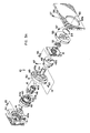
- a band pass filter 13 may be included as illustrated in Figure 2 to narrow the transmitted wavelength spectrum of the light source 11, depending on the type of light source used.As shown in Figure 2, the infrared light source 11, collimating optics 12, band pass filter 13, and polarizer 14 are positioned in optical alignment about an axis 20, hereinafter described in more detail, such that the polarizer 14 intercepts at least a portion of the infrared light emitted by source 11, to produce a polarized beam of light. It is understood that the collimating optics 12, band pass filter 13, and polarizer 14 may be any suitable apparatus well-known in the industry. A preferred construction of these parts is illustrated in more detail in Figures 3A and 3B.
- the infrared light emitting diode 11 is mounted to a diode holder 41.
- the diode holder 41 is mounted to a diode heat sink 42 by means of one or more screws 43.
- the heat sink 42 has an internally threaded bore 42a.
- Retaining ring 40 has a threaded exterior 40a for threading into the internally threaded bore 44a of a positioning mount 44, for securing the heat sink 42 into fixed coaxial position within the positioning mount 44, about the axis 20.
- the collimating optics 12 includes a pair of lenses 45a and 45b and collimating lens holder 46.
- lens 45a is a DCX lens 18mm x 39mm FL from Edmund Scientific Company, Part No. 95247 and lens 45 is a DCX lens 9mm x llmm FL, Edmund Scientific Company, Part No. 94823.
- the collimating lens holder 46 has a threaded exterior portion 46a that threads into the threaded interior bore 42a of the diode heat sink 42, for mounting the lenses in coaxial alignment with the light source 11.
- the polarimeter means 14 includes a polarizer 14a, polarizer rotator 49 and adapter 48.
- Polarizer 14a is coaxially positioned in the bore 48a of the polarizer adapter 48 and is held in the desired angular position by set screw 47.
- the polarizer 14a is a Karl Lambercht Model No. MGT25A10.
- the adapter 48 is coaxially mounted in the bore 49a within the polarizer rotator 49.
- the adapter 48 is secured in position by set screws 50.
- An iris 52 and lens 54 are mounted in a lens and iris mount 53.
- An iris mount clamp 51 is connected to the lens and iris mount 53 by means of a plurality of screws 55, one of which is illustrated in Figure 3A.
- the lens and iris mount 53 is mounted within circular opening 56a in lens bulk head 56 and is held in position by set screws 57.
- Lens 54 further collimates the beam.
- FIG. 3B which is an exploded extension of Figure 3A, the lens bulk head 56 is again illustrated and a sample block 60 is positioned for mounting adjacent to the lens bulk head 56.
- a sample block clamp 59 and screw 58 position and hold a sample cell 15 on the sample block 60.
- a window bulk head 62 having a window 61 is positioned adjacent the sample block 60 with the window 61 coaxially aligned along the axis 20.
- Lens 54 and window 61 contain liquid that may spill from loading and unloading the sample cell 15 between the lens bulk head 56 and window bulk head 62.
- the detector 16 includes a beam splitting prism polarizer 16a, prism mount 65 and prism mount clamp 63.
- the beam splitting prism polarizer 16a is positioned in optical alignment with the window 61 along the axis 20 and mounted on a prism mount 65 and held in position by prism mount clamp 63 and screw 54.
- a first infrared light detector 17a is positioned in a detector mount 72a.
- the mount 72a has a threaded inner bore 72c for mounting to a threaded exterior 71c of detector lens housing 71a.
- a detector lens 70a is positioned in detector retainer 69a.
- the detector retainer 69a mates with the detector lens housing 71a.
- This detector assembly is positioned in groove 66a of detector mount base 66 and is held in position by detector mounting clamp 67a and screw 68a.
- a second infrared light detector 17b is positioned in a detector mount 72b.
- the mount 72b has a threaded inner bore 72d for mounting to a threaded exterior 71d of a detector lens housing 71b.
- Detector lens 70b is positioned in a detector retainer 69b.
- the detector retainer 69b mates with the detector lens housing 71b.
- This detector assembly is positioned in groove 66b of detector mount base 66 and is held in positioned by detector mounting clamp 67b and screw 68b.
- Detector lenses 70a and 70b collect the respective portions of the beam so that the beam falls on the active area of infrared light detectors 17a and 17b respectively.
- a 90° connector 73 is connected to the second detector 17b and a straight connector 74 is connected to the first detector 17a.
- the connectors 73 and 74 carry electrical signals from the detectors 17b and 17a respectively, as herein after described in more detail.
- a sample cell 15 is provided for containing a sample of a dark sugar solution. While as shown in Figure 7, the sample cell 15 is a three dimensional closed container and is for use in a batch type testing process, it is understood that the sample cell 15 may be modified to provide for continuous process testing. The flow of the dark sugar solution into and out of the sample cell 15 for continuous process testing is indicated by the dashed lines 15a and 15b in Figure 2.
- the polarized and collimated light beam is projected through the polarimeter system along the axis 20.
- the detector 16 is operatively connected to intercept the polarized infrared light beam passing through the sample container 15 and produces a signal or signals in response to the rotational condition of the polarized beam.
- the detector 16 includes a Karl Lambrecht Model Number SBT 210-45 anaylzer beam splitting prism 16a.
- the beam splitting prism polarizer 16a separates the polarized light into its two components, one being referred to as the horizontal component and the other as the vertical component.
- Infrared light detectors 17a and 17b intercept, measure and convert the infrared light intensity of the horizontal and vertical polarized beams respectively into electrical signals.
- the infrared light detectors 17a and 17b may be photodiodes, photo-transistors, or photo-multipliers or any other suitable infrared light detectors.
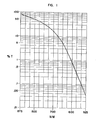
- Figure 1 is a graph illustrating the transparency percentage of a beet sugar molasses (dark sugar) solution to various light wavelengths. As can be seen, the solution is only 0.3 percent transparent when subjected to light waves of 575 nanometers, 17 percent at 700 nanometers and approximately 80 percent at 875 nanometers. It can be seen that the molasses solution is from 1 to 3 orders of magnitude more transparent to the infrared wavelengths (700 nanometers and above) than to light in the 500 to 633 nanometer range (visible light). Other dark sugar solutions have similar light transparency properties.
- the infrared light source 11 emits light having a wavelength greater than or equal to 700 nanometers and preferably 875 nanometers or above.
- a sample of the optically active material is placed in the sample container 15.
- Infrared light emitted from the infrared light source 11 is projected along the axis 20 through the collimating optics 12 and band pass filter 13 to the polarizer 14.
- the polarized beam from the polarizer 14 is directed toward and through the sample in the sample container 15.
- the polarized beam After passing through the sample, the polarized beam enters the detector 16 where it passes through the beam splitting prism 16a which splits the polarized light into its two components, one being horizontally polarized and the other vertically polarized.
- the infrared light detectors 17a and 17b are respectively energized by the horizontally and vertically polarized signals and produce electrical signals proportional to the respective energy levels of the horizontal and vertical component light beams.
- the electrical signals can be processed by appropriate electrical or electronic apparatus to extract information therefrom as to the rotation angles of the beam as it passed through the solution sample. Such information can be correlated to the percentage of sugar content of the sample solution, can be used to generate other calculations or can be directly used to perform or regulate physical manipulations or operations (as for example, process control operations within a sugar-beet processing factory).
- the post-detection portion of the apparatus may use either analog or digital disciplines.
- such "electronic" portion of the apparatus is used for the purposes of measuring or calculating the percentage of sugar content of the solution contained within the sample container 15.
- computation or calculation is performed digitally, rather than through analog techniques. It will be understood, however, that the invention applies equally well to either digital or analog techniques and applies to any form of manipulation of the electrical signals derived from the detectors 17a and 17b, whether such manipulation be for obtaining a measurement or mathematical result or for performing or initiating the performance of a physical operation or command.
- a typical electronic output section for the apparatus may be illustrated by reference to a specific electronic structure used in association with the preferred embodiment.
- the electrical signals produced by the first detector 17a in response to the horizontal component of the polarized detected beam is carried by means of a signal flow path 25a to a Scaling electrical functional block 26.
- the electrical signal produced by the second detector 17b corresponding to the vertical component of the polarized detected beam is carried by means of a signal flow path 25b to a second input of the Scaling block 26.
- signal flow path may refer to one or a plurality of actual electrical wires or conductors.
- the Scaling function block 26 generally comprises one or a plurality of amplifier stages for conditioning the detected signals, so as to place the detected signals in proper format for subsequent manipulation or use by the digital or analog circuitry to which they will be applied.
- the conditioned signals from the Scaling functional block 26 are applied by means of a pair of signal flow paths 26a'and 26b to first and second input terminals of an Analysis functional block 28.
- the Analysis functional block 28 may comprise a digital computer.
- the Analysis functional block 28 comprises a type TM 990 computer manufactured by Texas Instruments, hereinafter described in more detail.
- the Analysis functional block 28 has a Keyboard/Input module 30 associated with it for providing communication between an operator and the Analysis circuit 28.
- the Keyboard 30 communicates with the Analysis 28 functional block by means of a signal flow path 30a.
- the Analysis functional block 28 communicates back- to an operator or the outside environment by means of signal flow paths 28a and 28b respectively illustrated in Figure 2 as communicating with a Display panel 31 and Alarm network 32. It will be understood that such output communication from the Analysis functional block 28 may otherwise be provided directly by means of one or more signal flow paths to the appropriate circuitry corresponding to the functions being performed by the Analysis functional block 28.
- the Analysis functional block 28 receives an additional sensed input signal by means of a signal flow path 34b from a temperature sensor 34 operatively connected with the sample container 15 by means of the signal flow path 34a, to sense the temperature of the solution contained within the sample container 15.
- the temperature sensing block 34 may represent any appropriate temperature sensing element (not specifically illustrated in the Drawing, see Fig. 7) capable of generating a detectable electrical output signal in response to a sensed temperature.
- the digital computer comprising the Analysis functional block 28 performs the calculations for computing the percentage of sugar content of the sampled solution, in response to the sensed electrical input information received from the signal flow paths 26a, 26b and 34b. Any appropriate analytical technique can be employed for making such determination in response to the received detected digital information.
- information corresponding to and defining a non-linear curve representing percentage of sugar content concentrations for various polarization angular rotations is stored within the memory of the Analysis computer 28.
- the respective detected signals from the detectors 17a and 17b is processed by the Scaling functional block 26 to provide digital information signals by means of the signal flow paths 26a and 26b which the Analysis computer 28 can correlate to specific points of the non-linear curve stored within its memory:
- such correlation is performed by the computer by a "least- squares fit" method. It will be understood, however, that any appropriate techniques could be employed for determining such correlation.
- the computer will display the resultant "correlation/fit" information by means of the Display 31 or the Alarm 32, that represents the degree of rotation of the polarized infrared light beam. Such information may be displayed in any appropriate manner such as in degrees of optical rotation, as sugar degrees rotation, or as a percentage of sugar content of the solution. Such techniques will be readily understood by those skilled in the art.
- the detected signals from the detectors 17a and 17b are processed by means of the Scaling functional block 26 in the manner illustrated in Figure 4.
- the detected signals from the detectors 17a and 17b are illustrated as entering the Scaling functional block 26 by means of the signal flow paths 25a and 25b respectively, which apply such detected signals to a pair of amplifier stages respectively schematically identified at 100 and 101.
- the output signals respectively from the amplifier stages 100 and 101 are carried by means of the signal flow paths 26c and 26d through preamplifier stages 102 and 103 respectively to first and second A/D converter networks 104 and 105.
- Each of the preamplifier stages 102 and 103 is illustrated as having a "gain" and an "off-set" adjustment.
- the A/D converter networks are, in the preferred embodiment, 16-bit converter networks suitable for converting the applied analog input signals received thereby to a 16-bit digital output representation.
- the pair of 16-bit digital signals are carried by the signal flow paths 26a and 26b respectively-to the Analysis computer 28 where they are used in the correlation determination.
- the two channels of the Scaling functional block 26 are of generally like construction.
- the Amplifier 100 (101) and preamplifier 102 (103) portions of the scaling circuitry 26 are illustrated in more detail in Figure 5, as they are constructed in the preferred embodiment.
- the input signal flow path 25 is illustrated as a pair of input terminals respectively connected across the anode and cathode of one of the detector diodes 17.
- the anode of the detector diode 17 is connected to the non-inverting input terminal of a first amplifier 120 and is also connected to the common or reference voltage.
- the cathode of the detector diode is connected to the inverting input terminal of the amplifier 120.
- the feedback network of amplifier 120 comprises a capacitor 121 and a resistor 122 connected in parallel between the output and inverting input terminals of the amplifier 120.
- the output of amplifier 120 is connected by means of a resistor 123 to the inverting input of a second amplifier 124.
- the non-inverting input terminal of amplifier 124 is connected by means of a resistor 125 to the reference potential.
- the feedback network of amplifier 124 comprises a capacitor 126 and a variable resistor 127 connected in parallel between the output terminal and inverting input terminal of the amplifier 124.
- the output signal from amplifier 124 provides the signal carried by signal flow path 26c or 26d,' and also is applied by means of a resistor 128 to the inverting input terminal of an amplifier 130 of the preamplifier stage 102 (103).
- the non-inverting input terminal of amplifier 130 is connected by means of a variable resistor 131 to the reference potential.
- the voltage level applied across resistor 131 is controlled by means of a regulated voltage supply, generally designated at 132.
- the feedback loop for amplifier 130 is provided by means of a variable resistor 170 connected between the output and inverting input terminals of amplifier 130.
- the output signal from amplifier 130 provides the analog signal excitation for the A/D converter 104 or 105 by means of the signal flow path 102a or 103a respectively.
- the variable resistance settings of the preamplifier 102 allow for "gain" and "off-set” adjustments, as is well-known in the amplifier art.
- the signals carried from the Scaling functional block 26 by means of the signal flow paths 26c and 26d are applied to a current control network, generally designated at 36.
- a preferred construction of the current control network 36 is illustrated in more detail in Figure 6.
- the signal flow paths 26c and 26d are respectively connected by means of resistors 140 and 141 to the inverting input terminal of an amplifier 142.
- the non-inverting input terminal of amplifier 142 is connected through a variable resistor 143 to the reference potential, and the voltage across resistor 143 is regulated by a regulated voltage source (not illustrated).
- a feedback resistor 144 is connected between the output terminal and the inverting input terminal of amplifier 142.
- Amplifier 142 acts as a comparator for the combined detected input signals applied by means of the signal flow paths 26c and 26d against the predetermined voltage established by resistor 143.
- the output signal from amplifier 142 supplied by means of a resistor 145 to the inverting input terminal of an amplifier 146.
- the non-inverting input terminal of amplifier 146 is directly connected to the reference potential, and a feedback capacitor 147 is connected between the output and inverting input terminals of amplifier 146, making amplifier 146 operable to integrate the signal output from amplifier 142.
- the output terminal of amplifier 146 is connected through a switch 148 and resistor 149 to the base of an npn transistor 150.
- the collector of transistor 150 is directly connected to the cathode of the infrared source diode 11, and the emitter of transistor 150 is connected through a current limiting resistor 151 to the reference potential.
- the emitter of transistor 150 is also connected through a variable resistor 152 to the base of a pnp transistor 153.
- Transistor 153 further has an emitter connected through a resistor 154 to a fused voltage supply source, which source is also connected by means of a resistor 155 to the base of transistor 153.
- the collector of transistor 153 is connected by means of a variable resistor 156 to the anode of the infrared diode source 11.
- the transistor 153 and associated resistors function as a supply source of current for energizing the infrared diode 11, and the transistor 150 operates as a current driver circuit for regulating the current flow through diode 11 in response to the integrated drive signal from amplifier 146.
- Resistor 151 limits the maximum current that can be drawn through the source diode 11.
- the switch 48 provides for manual (non-regulated) energization of the source diode 11.
- the base of transistor 150 is connected through the series combination of resistor 149, and a variable resistor 160 to the cathode of a zener diode 161.
- the anode of zener diode 161 is directly connected to the reference potential.
- the cathode of diode 161 is also connected by means of a resistor 162 to-the positive supply potential.
- the zener diode 161 establishes a 6.2 volt regulated voltage level at its cathode.
- the current control circuit 36 controls the current flow through the source diode 11 in response to the total intensity of polarized light detected by the detectors 17a and 17b.
- the regulation of source diode current is maintained at a level such that the detectors 17a and 17b always are exposed to the same "total" (i.e. sum of detected light intensity amounts) amount of light intensity, regardless of the absorption by the sampled solution.
- Such current control is, however, limited by the current flow capability of diode 11, by means of the current limiting resistor 150.
- Such light intensity compensates for any nonlinearities in the detectors 17a and 17b that may affect the detected readings of such devices.
- the light control regulator also permits operation of the light source at the lowest energy level possible that will still provide an adequate light level, to extend the operating life of the light source 11.
- FIG 8. An alternate configuration for the Scaling functional block 26, that could elminate the need or desirability for the Current Control network 36 is illustrated in Figure 8.
- a "prime" i.e. *
- Signal flow from paths 25a' and 25b' passes through amplifiers 100, 101, 102 and 103 as previously described.
- H and V signals
- Divider network 27 which forms the ratio (H/V) of the input signals.
- the ratio signal is then carried by means of the signal flow path 26e to the Analysis section 28.
- the advantage of forming a ratio is that intensity variations in the detected signals carried by paths 25a' and 25b' identically cancel one another in the (H/V) output signal.
- temperature considerations for such analyzed samples are not generally relevant in laboratory situations, they may become particularly important in on-line (i.e. continuous flow-through) applications in factory situations wherein the sampling procedure may be exposed to severe temperature gradients under operative conditions.
Landscapes
- Physics & Mathematics (AREA)
- Spectroscopy & Molecular Physics (AREA)
- Engineering & Computer Science (AREA)
- General Physics & Mathematics (AREA)
- General Health & Medical Sciences (AREA)
- Chemical & Material Sciences (AREA)
- Analytical Chemistry (AREA)
- Biochemistry (AREA)
- Life Sciences & Earth Sciences (AREA)
- Immunology (AREA)
- Pathology (AREA)
- Health & Medical Sciences (AREA)
- Microelectronics & Electronic Packaging (AREA)
- Multimedia (AREA)
- Power Engineering (AREA)
- Investigating Or Analysing Materials By Optical Means (AREA)
Applications Claiming Priority (2)
| Application Number | Priority Date | Filing Date | Title |
|---|---|---|---|
| US06/352,321 US4467204A (en) | 1982-02-25 | 1982-02-25 | Apparatus and method for measuring optically active materials |
| US352321 | 1994-12-08 |
Publications (1)
| Publication Number | Publication Date |
|---|---|
| EP0087535A1 true EP0087535A1 (de) | 1983-09-07 |
Family
ID=23384663
Family Applications (1)
| Application Number | Title | Priority Date | Filing Date |
|---|---|---|---|
| EP82306279A Ceased EP0087535A1 (de) | 1982-02-25 | 1982-11-25 | Vorrichtung und Verfahren zur Messung optisch aktiver Substanzen |
Country Status (4)
| Country | Link |
|---|---|
| US (1) | US4467204A (de) |
| EP (1) | EP0087535A1 (de) |
| JP (1) | JPS58153145A (de) |
| CA (1) | CA1183364A (de) |
Cited By (5)
| Publication number | Priority date | Publication date | Assignee | Title |
|---|---|---|---|---|
| EP0179016A1 (de) * | 1984-09-25 | 1986-04-23 | Richard Distl | Zweistrahl-Echtzeitpolarimeter |
| WO1988003266A1 (en) * | 1986-10-24 | 1988-05-05 | David Murray Goodall | Optical apparatus and method |
| AU619041B2 (en) * | 1988-09-07 | 1992-01-16 | Bodenseewerk Perkin-Elmer Gmbh | Polarimeter |
| EP0536985A1 (de) * | 1991-10-11 | 1993-04-14 | Optical Activity Limited | Polarimeter |
| DE19815932A1 (de) * | 1998-04-09 | 1999-10-21 | Glukomeditech Ag | Verfahren zur Miniaturisierung eines Polarimeters zur Analyse niedrig konzentrieter Komponenten im flüssigen Meßgut auf optischer Basis sowie Vorrichtung zu seiner Durchführung |
Families Citing this family (16)
| Publication number | Priority date | Publication date | Assignee | Title |
|---|---|---|---|---|
| JPH0672807B2 (ja) * | 1984-09-29 | 1994-09-14 | 株式会社島津製作所 | 旋光度測定装置 |
| US5209231A (en) * | 1990-11-02 | 1993-05-11 | University Of Connecticut | Optical glucose sensor apparatus and method |
| DE4128458C2 (de) * | 1991-08-28 | 1994-02-10 | Siemens Ag | Verfahren und Vorrichtung zur Bestimmung der Konzentration einer Komponente, insbesondere von Glucose, einer flüssigen optisch aktiven Substanz, insbesondere der Körperflüssigkeit eines Patienten, durch Polarimetrie |
| DE4244717B4 (de) * | 1992-08-13 | 2004-12-09 | Mächler, Meinrad | Spektroskopisches System |
| JPH07318429A (ja) * | 1994-05-20 | 1995-12-08 | Yanmar Agricult Equip Co Ltd | 旋光角の測定方法 |
| RU2107280C1 (ru) * | 1996-11-15 | 1998-03-20 | Институт молекулярной биологии им.В.А.Энгельгардта РАН | Способ определения в анализируемой жидкости биологически активного вещества и устройство для его осуществления |
| DE19826294C1 (de) * | 1998-06-12 | 2000-02-10 | Glukomeditech Ag | Polarimetrisches Verfahren zur Bestimmung der (Haupt-)Schwingungsebene polarisierten Lichts auf etwa 0,1m DEG und miniaturisierbare Vorrichtung zu seiner Durchführung |
| DE19950648A1 (de) * | 1999-10-21 | 2001-04-26 | Wolfgang Urban | NO-Nachweis durch Faraday-Nullfeldmodulation |
| DE10001810B4 (de) * | 2000-01-18 | 2010-05-06 | A. Krüss Optronic GmbH | Polarimeter |
| DE10020613C2 (de) * | 2000-04-27 | 2002-02-28 | Glukomeditech Ag | Verfahren zur langzeitstabilen und gut reproduzierbaren polarimetrischen Messung der Konzentrationen der Bestandteile wässriger Lösungen sowie Vorrichtung zur Durchführung dieses Verfahrens |
| SE523230C2 (sv) * | 2001-09-20 | 2004-04-06 | Roplan Dev Ct Ab | Anordning för att täta en passage mellan en roterbar axel och en stationär vägg. |
| IL145683A0 (en) * | 2001-09-26 | 2002-06-30 | Enoron Technologies Ltd | Apparatus and method for measuring optically active materials |
| US6717665B2 (en) * | 2002-03-13 | 2004-04-06 | Rudolph Research Analytical | Polarimeter |
| US7248357B2 (en) * | 2004-10-29 | 2007-07-24 | Gas Technology Institute | Method and apparatus for optically measuring the heating value of a multi-component fuel gas using nir absorption spectroscopy |
| WO2007002182A1 (en) * | 2005-06-21 | 2007-01-04 | Stheno Corporation | Improved systems and methods for chiral detection and analysis |
| US9295419B2 (en) * | 2013-05-06 | 2016-03-29 | T.G.M. Technologies Ltd | Method and system for a non-invasive measurement of optically active component concentration |
Citations (4)
| Publication number | Priority date | Publication date | Assignee | Title |
|---|---|---|---|---|
| US3411342A (en) * | 1966-06-08 | 1968-11-19 | Staley Mfg Co A E | Apparatus for continuously measuring optically active materials |
| DE1698292B2 (de) * | 1968-02-10 | 1973-06-28 | Fa. Carl Zeiss, 7920 Heidenheim | Verfahren und einrichtung zum messen des reinheitsquotienten von zwischenprodukten in der zuckerfabrikation |
| GB2096764A (en) * | 1981-04-10 | 1982-10-20 | Ranks Hovis Mcdougall Ltd | Measuring optical rotation |
| EP0030610B1 (de) * | 1979-10-31 | 1986-03-05 | Arno Dr. Dipl.-Phys. Müller | Verfahren und Vorrichtung zur quantitativen Bestimmung optisch aktiver Substanzen |
Family Cites Families (17)
| Publication number | Priority date | Publication date | Assignee | Title |
|---|---|---|---|---|
| DE30610C (de) * | R. BAYNES, J. FEAREN-SIDE und W. PH. THOMPSON in Liverpool, County of Lancaster, England | Verfahren und Apparate zum Bleichen und Reinigen von Petroleum und anderen destillirbaren Oelen | ||
| US2766652A (en) * | 1951-12-03 | 1956-10-16 | Austin N Stanton | Device for determining the degree of rotation of polarized light |
| BE605571A (de) * | 1960-06-29 | |||
| US3283645A (en) * | 1962-04-26 | 1966-11-08 | Wada Akiyoshi | Laminar flow dichroism polarimeter |
| DE1226328B (de) * | 1965-03-13 | 1966-10-06 | Bodenseewerk Perkin Elmer Co | Vorrichtung zur gleichzeitigen Messung von optischer Drehung und Zirkular-Dichroismus |
| GB1142501A (en) * | 1965-04-21 | 1969-02-12 | Pye Ltd | Improvements in or relating to the measurement of circular dichroism |
| US3468607A (en) * | 1966-12-06 | 1969-09-23 | Hawaiian Sugar Planters Assoc | Apparatus for the continuous analysis of a liquid stream containing dissolved solids of which a portion are optically active in solution |
| US3508830A (en) * | 1967-11-13 | 1970-04-28 | Shell Oil Co | Apparatus for light scattering measurements |
| US3586443A (en) * | 1968-04-22 | 1971-06-22 | Cary Instruments | Circular dichroism measurement system |
| US3625593A (en) * | 1969-02-03 | 1971-12-07 | Rca Corp | Electrical control of light polarization utilizing the optical property of fluids |
| DE1915891B2 (de) * | 1969-03-28 | 1971-03-18 | Vorrichtung zur bestimmung der lagekoordinaten eines punktes mittels eines laserstrahles | |
| US3724957A (en) * | 1971-03-04 | 1973-04-03 | Yokogawa Electric Works Ltd | Concentration measuring apparatus |
| GB1386963A (en) * | 1971-03-10 | 1975-03-12 | Nat Res Dev | Testing of optically active substances |
| DE2164670A1 (de) * | 1971-12-24 | 1973-06-28 | Bbc Brown Boveri & Cie | Verfahren zur kontinuierlichen messung organischer substanzen in wasser und anordnung zur durchfuehrung des verfahrens |
| US3856408A (en) * | 1972-06-05 | 1974-12-24 | Svenska Traeforskningsinst | Apparatus for measuring the optically birefringent properties of a liquid sample |
| IT1031452B (it) * | 1975-02-04 | 1979-04-30 | Leeds & Northrup Spa | Analizzatore a raggi infrarossi con energia radiante cost ante |
| US4152594A (en) * | 1977-03-28 | 1979-05-01 | Leybold-Heraeus Gmbh & Co. Kg. | Apparatus for the photo-optical measurement of the absorption behavior of solid, liquid and gaseous media |
-
1982
- 1982-02-25 US US06/352,321 patent/US4467204A/en not_active Expired - Lifetime
- 1982-11-05 CA CA000414980A patent/CA1183364A/en not_active Expired
- 1982-11-25 EP EP82306279A patent/EP0087535A1/de not_active Ceased
- 1982-12-22 JP JP57224050A patent/JPS58153145A/ja active Pending
Patent Citations (4)
| Publication number | Priority date | Publication date | Assignee | Title |
|---|---|---|---|---|
| US3411342A (en) * | 1966-06-08 | 1968-11-19 | Staley Mfg Co A E | Apparatus for continuously measuring optically active materials |
| DE1698292B2 (de) * | 1968-02-10 | 1973-06-28 | Fa. Carl Zeiss, 7920 Heidenheim | Verfahren und einrichtung zum messen des reinheitsquotienten von zwischenprodukten in der zuckerfabrikation |
| EP0030610B1 (de) * | 1979-10-31 | 1986-03-05 | Arno Dr. Dipl.-Phys. Müller | Verfahren und Vorrichtung zur quantitativen Bestimmung optisch aktiver Substanzen |
| GB2096764A (en) * | 1981-04-10 | 1982-10-20 | Ranks Hovis Mcdougall Ltd | Measuring optical rotation |
Cited By (7)
| Publication number | Priority date | Publication date | Assignee | Title |
|---|---|---|---|---|
| EP0179016A1 (de) * | 1984-09-25 | 1986-04-23 | Richard Distl | Zweistrahl-Echtzeitpolarimeter |
| WO1988003266A1 (en) * | 1986-10-24 | 1988-05-05 | David Murray Goodall | Optical apparatus and method |
| US5012101A (en) * | 1986-10-24 | 1991-04-30 | National Research Development Corporation | Optical apparatus and method |
| AU619041B2 (en) * | 1988-09-07 | 1992-01-16 | Bodenseewerk Perkin-Elmer Gmbh | Polarimeter |
| EP0536985A1 (de) * | 1991-10-11 | 1993-04-14 | Optical Activity Limited | Polarimeter |
| DE19815932A1 (de) * | 1998-04-09 | 1999-10-21 | Glukomeditech Ag | Verfahren zur Miniaturisierung eines Polarimeters zur Analyse niedrig konzentrieter Komponenten im flüssigen Meßgut auf optischer Basis sowie Vorrichtung zu seiner Durchführung |
| DE19815932C2 (de) * | 1998-04-09 | 2000-06-21 | Glukomeditech Ag | Verfahren zur Miniaturisierung eines Polarimeters zur Analyse niedrig konzentrierter Komponenten im flüssigen Meßgut auf optischer Basis sowie Vorrichtung zu seiner Durchführung |
Also Published As
| Publication number | Publication date |
|---|---|
| JPS58153145A (ja) | 1983-09-12 |
| US4467204A (en) | 1984-08-21 |
| CA1183364A (en) | 1985-03-05 |
Similar Documents
| Publication | Publication Date | Title |
|---|---|---|
| US4467204A (en) | Apparatus and method for measuring optically active materials | |
| US5825478A (en) | Multifunctional photometer apparatus | |
| US5500768A (en) | Laser diode/lens assembly | |
| EP0215648B1 (de) | System zur chemischen Fernanalyse | |
| US4981362A (en) | Particle concentration measuring method and device | |
| US4622845A (en) | Method and apparatus for the detection and measurement of gases | |
| US20030202179A1 (en) | Ultrasensitive spectrophotometer | |
| CA1330717C (en) | Concentration determination with multiple wavelength flash photometers | |
| EP0091126B1 (de) | Fluorimeter | |
| JPS61116646A (ja) | ケイ光光度計及びケイ光測定方法 | |
| NO304620B1 (no) | FremgangsmÕte og apparat for spektroskopisk mÕling av konsentrasjonen av en gass | |
| US2245124A (en) | Measuring apparatus | |
| US5654796A (en) | Apparatus and method for mapping plasma characteristics | |
| US3591801A (en) | Double beam optical absorption photometer having sample and reference chambers positioned along a single optical axis | |
| CA2111963A1 (en) | Method and apparatus for multivariate characterization of optical instrument response | |
| US5745243A (en) | Photometer apparatus | |
| US3730627A (en) | Signal processor | |
| US5694206A (en) | Spectrophotometric system using a pH/ISE meter for calibration | |
| CA1207550A (en) | Apparatus and method for measuring refractive index of liquids | |
| US5321970A (en) | Method and apparatus for calibrating a spectrometer | |
| US5760895A (en) | Optical monitor for water vapor concentration | |
| US6218666B1 (en) | Method of determining the concentration of a gas in a gas mixture and analyzer for implementing such a method | |
| EP0176826A2 (de) | Verfahren und Vorrichtung für spektrale Zweistrahldurchlässigkeitsmessungen | |
| US3428796A (en) | Concentration computer with logarithmic computation of photometric apparatus readings | |
| US3332313A (en) | Apparatus for absorption spectra analysis |
Legal Events
| Date | Code | Title | Description |
|---|---|---|---|
| PUAI | Public reference made under article 153(3) epc to a published international application that has entered the european phase |
Free format text: ORIGINAL CODE: 0009012 |
|
| AK | Designated contracting states |
Designated state(s): BE DE FR GB IT |
|
| 17P | Request for examination filed |
Effective date: 19840223 |
|
| STAA | Information on the status of an ep patent application or granted ep patent |
Free format text: STATUS: THE APPLICATION HAS BEEN REFUSED |
|
| 18R | Application refused |
Effective date: 19881002 |
|
| RIN1 | Information on inventor provided before grant (corrected) |
Inventor name: SAWICKI, CHARLES A. Inventor name: KYSILKA, JAMES O. |