EP0087552A2 - Appareil pour la mesure de débit de fluide et l'application de l'appareil - Google Patents
Appareil pour la mesure de débit de fluide et l'application de l'appareil Download PDFInfo
- Publication number
- EP0087552A2 EP0087552A2 EP83100079A EP83100079A EP0087552A2 EP 0087552 A2 EP0087552 A2 EP 0087552A2 EP 83100079 A EP83100079 A EP 83100079A EP 83100079 A EP83100079 A EP 83100079A EP 0087552 A2 EP0087552 A2 EP 0087552A2
- Authority
- EP
- European Patent Office
- Prior art keywords
- plastic tube
- proportional
- signal
- probe
- amplifier
- Prior art date
- Legal status (The legal status is an assumption and is not a legal conclusion. Google has not performed a legal analysis and makes no representation as to the accuracy of the status listed.)
- Granted
Links
- 238000005259 measurement Methods 0.000 title description 3
- 239000007788 liquid Substances 0.000 claims abstract description 16
- 239000000523 sample Substances 0.000 claims description 21
- 239000003146 anticoagulant agent Substances 0.000 claims description 20
- 229940127219 anticoagulant drug Drugs 0.000 claims description 20
- 230000002572 peristaltic effect Effects 0.000 claims description 12
- 238000011156 evaluation Methods 0.000 claims description 8
- 230000005540 biological transmission Effects 0.000 claims description 5
- 239000013078 crystal Substances 0.000 claims description 3
- 239000012530 fluid Substances 0.000 claims description 3
- 210000000056 organ Anatomy 0.000 claims description 2
- 239000010453 quartz Substances 0.000 claims description 2
- VYPSYNLAJGMNEJ-UHFFFAOYSA-N silicon dioxide Inorganic materials O=[Si]=O VYPSYNLAJGMNEJ-UHFFFAOYSA-N 0.000 claims description 2
- 238000002604 ultrasonography Methods 0.000 claims description 2
- GJAARPKBDFKHFS-UHFFFAOYSA-N Gerin Natural products COC(=O)C(=C)C1CC2C(=C)C(=O)C=CC2(C)CC1OC(=O)C GJAARPKBDFKHFS-UHFFFAOYSA-N 0.000 claims 1
- 239000003112 inhibitor Substances 0.000 claims 1
- 238000000034 method Methods 0.000 abstract description 8
- 230000015271 coagulation Effects 0.000 abstract 3
- 238000005345 coagulation Methods 0.000 abstract 3
- 239000003795 chemical substances by application Substances 0.000 abstract 2
- 239000008280 blood Substances 0.000 description 14
- 210000004369 blood Anatomy 0.000 description 14
- 238000010586 diagram Methods 0.000 description 4
- 238000006243 chemical reaction Methods 0.000 description 2
- 239000000306 component Substances 0.000 description 2
- 230000000694 effects Effects 0.000 description 2
- 230000017531 blood circulation Effects 0.000 description 1
- 239000012503 blood component Substances 0.000 description 1
- 238000010241 blood sampling Methods 0.000 description 1
- 230000001419 dependent effect Effects 0.000 description 1
- 230000010358 mechanical oscillation Effects 0.000 description 1
- 239000002245 particle Substances 0.000 description 1
- 239000003755 preservative agent Substances 0.000 description 1
- 230000002335 preservative effect Effects 0.000 description 1
- 230000001629 suppression Effects 0.000 description 1
- 238000002560 therapeutic procedure Methods 0.000 description 1
Images


Classifications
-
- G—PHYSICS
- G01—MEASURING; TESTING
- G01F—MEASURING VOLUME, VOLUME FLOW, MASS FLOW OR LIQUID LEVEL; METERING BY VOLUME
- G01F1/00—Measuring the volume flow or mass flow of fluid or fluent solid material wherein the fluid passes through a meter in a continuous flow
- G01F1/66—Measuring the volume flow or mass flow of fluid or fluent solid material wherein the fluid passes through a meter in a continuous flow by measuring frequency, phase shift or propagation time of electromagnetic or other waves, e.g. using ultrasonic flowmeters
-
- A—HUMAN NECESSITIES
- A61—MEDICAL OR VETERINARY SCIENCE; HYGIENE
- A61B—DIAGNOSIS; SURGERY; IDENTIFICATION
- A61B8/00—Diagnosis using ultrasonic, sonic or infrasonic waves
- A61B8/06—Measuring blood flow
Definitions
- the present invention relates to a device for measuring the flow rate by means of ultrasound in a plastic tube with a transmitter element, with a probe which is connected on the one hand to the transmitter element and on the other hand emits a signal proportional to the flow rate, and with an evaluation device connected to the probe in order to obtain a device to generate an output signal proportional to the flow and the use thereof in a device for taking physiological liquids and admixing a liquid anticoagulant with a cutlery attachable to a dispenser and a peristaltic pump for supplying the anticoagulant.
- the blood dispensed by a donor is passed into a bag or bottle, in which or already It contains a liquid anticoagulant and blood preservative.
- the aim of the invention is to provide a device of the type mentioned at the outset with which the amount of blood delivered by a donor can be measured in order to be able to supply an anticoagulant to the donated blood in the correct ratio.
- the probe has a body with an elongated recess into which the hose can be inserted and a cover in order to fix the hose in the recess.
- the oscillating elements consist of piezoelectric crystal and are embedded in the body at a distance from one another such that at least one surface section of the oscillating elements is flush with the surface of the recess.
- the oscillating elements are arranged parallel to the longitudinal axis of the recess, those facing the recess Include surfaces at an angle of at least 90 o .
- the transmitter element has a temperature-compensated circuit structure, the output signal of which has a frequency of 9.5 MHz, and if the calibration amplifier is an adjustable amplifier for converting the speed-proportional signal into a quantity-proportional signal.
- the cutlery further comprises a second bag containing the anticoagulant, a second plastic tube and an organ that can be inserted into the first plastic tube for connecting the second plastic tube, so that the probe can be applied to the first plastic tube in order to Measure the amount of the physiological fluid dispensed, and that the peristaltic pump can be placed on the second plastic tube and is connected to the evaluation device in order to be dependent the amount donated to promote an amount of the anticoagulant into the first plastic tube.
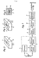
- the device essentially contains a transmission element 1, a probe 2 and an evaluation device.
- the probe 2 has two oscillating elements 3 and 4, which are electrically connected to the transmission element 1 or the evaluation device and can be placed on a plastic tube.
- a demodulator device 5 with a selectively controlled amplifier 6 and a demodulator 7, which are connected in series, and a converter device 8 with a control amplifier 9, a demodulator 10 and a calibration amplifier 11.
- the probe 2, FIGS. 3, 4, 5 consists of the probe body 15, with the elongated recess 17 for receiving the tube and the cover 16, which serves primarily to fix the tube in the probe body 15.
- the vibration elements 3, 4, which are spaced apart in the recess 17, are pressed against the outer surface of the hose. For good vibration transfer must contact between the oscillating elements 3, 4 and the outer surface of the hose successes n possible without an air gap.
- the oscillating elements 3, 4 lie transversely to the longitudinal axis of the recess 17.
- the oscillating elements 3, 4 are parallel to the longitudinal axis of the recess 17.
- the oscillating elements 3, 4 are arranged at an angle, as a result of which a certain focusing effect occurs, such that the measurement is mainly in the middle of the hose takes place where the liquid velocity is greatest. This improves the useful signal / interference signal ratio.
- the transmitter element 1 which is arranged and temperature-compensated in such a way that temperature synchronization is achieved with the other elements of the demodulator device 5, emits an output signal of 9.5 MHz, which is applied to the one oscillating element 3 of the probe.
- the oscillating element 3 consisting of piezoelectric crystal is set into mechanical oscillation by the signal of the transmitting element 1.
- the vibration is transmitted through the hose wall to the medium flowing in the hose. This vibration is reflected both on the hose, on the probe with cover 15, 16 and on the flowing medium.
- the vibration reflected by the particles contained in the flowing medium exhibits a frequency shift which is proportional to the speed of the flowing medium (Doppler effect).
- the second vibrating element 4 of the probe is excited by the reflected vibrations and emits an electrical output signal.
- the amplifier 6 connected downstream of the oscillating element 4 processes the RF signal to such an extent that it demodulates in the subsequent demodulator 7 can be.
- Both the RF amplifier 6 and the demodulator 7 are designed in such a way that the highest possible suppression of the non-informational content for the known reception frequencies. frequencies.
- the resulting LF signal is then fed to the converter device 8.
- a control amplifier 9 ensures a further improvement of the LF signal, in particular with regard to the useful signal / interference signal ratio, after which this is converted into a DC voltage in a subsequent demodulator 10.
- the voltage is now proportional to the speed of the flowing medium.
- the calibration amplifier 11 ensures through its setting that the signal can be output linearly and proportionally.
- the evaluation device according to FIG. 2 initially follows the known configuration according to FIG. 1, but is distinguished within the demodulator device 5 by the fact that the RF amplifier 6 is provided with quartz filters to increase the selectivity.
- the converter device 8 has a substantially different structure in that the LF signal after the control amplifier 9 is converted into a digital signal with the analog / digital converter 12. In this form, it can now be processed by a microprocessor system 13. In addition to the conversion from speed-proportional to quantity-proportional signal units, further signal evaluations and signal influences can be carried out. Examples are: threshold and maximum value acquisition, acquisition of changes, generation of linear or non-linear output curves.
- the output signal is available in digital form or after renewed conversion in the digital / analog converter again as a DC voltage signal.
- FIG. 6 shows a block diagram of a device for taking blood and adding an anticoagulant with a set of cutlery.
- the removal kit essentially consists of a first bag 20 for receiving the donated blood, a second bag 21, in which an anticoagulant is contained, and a hose arrangement for establishing the connection between the dispenser and the first and second bags 20, 21.
- the hose arrangement consists of a connecting member 22 and three plastic sleeves 23, 24, 25 which are connected on the one hand to the connecting member 22 and on the other hand can be connected to the dispenser, the first bag 20 or the second bag 21.
- the connecting element 22 has a Y-shaped passage, to the trunk of which the plastic tube 23 leading to the dispenser and to the branches of which the plastic tube 24, 25 leading to the first or the second bag are connected.
- the device contains the flow measuring device described above, which can be applied via the probe 2 to the plastic tube 23 leading to the donor in order to measure the amount of blood donated, a peristaltic pump 26 with a pump control circuit 27 which is connected to the second bag 21 leading plastic hose 25 can be applied to supply the anticoagulant, a shut-off device 28 with a safety circuit 29, a display and operating part 30 and a voltage supply part 31.
- the peristaltic pump 26 is well known and is described in U.S. Patent No. 4,302,164.
- the shut-off device 28 consists of two mutually movable members (not shown) which, when actuated, compress the plastic hose 24 and thereby interrupt the flow.
- a switch 32 for switching the device on and off there is a switch 32 for switching the device on and off, a lamp 33 for displaying the switched-on state and a lamp 34 for switching on show that blood is being dispensed, a lamp 35 for indicating that the dispensing process has been interrupted and ended and a selector switch 36 for adjusting the amount of blood to be drawn.
- the voltage supply part 31 is connected to the flow measuring device, the pump control circuit 27 and the safety circuit 29 and supplies a supply voltage to them.
- the flow measuring device is connected to the pump control circuit 27 and the safety circuit 29.
- the safety circuit 29 is in turn connected to the shut-off device 28 and the pump control circuit 27.
- the device After inserting the cutlery, the device is switched on and the cutlery is attached to the dispenser. In the meantime, the peristaltic pump 26 is put into operation for so long and the anticoagulant is conveyed to the connecting member 22. The peristaltic pump 26 is then switched off.
- the flow measurement device When the blood flow begins, the flow measurement device outputs the signal proportional to the flow rate to the safety circuit 29 to determine the total flow rate and to the pump control circuit 27 to switch the peristaltic pump 28 on again and to control it in dependence on this signal.
- the peristaltic pump 27 conveys an amount of the anticoagulant, which corresponds to a previously calculated ratio, into the connecting member 22.
- the safety circuit 29 has limit value circuits (not shown) which actuate the shut-off device 28 when the quantity set at the switch 36 is reached, so that the blood withdrawal is stopped, and which trigger an acoustic signal when the preselected flow quantity is undershot, so that it is determined that blood sampling is not optimal.
Landscapes
- Health & Medical Sciences (AREA)
- Life Sciences & Earth Sciences (AREA)
- Physics & Mathematics (AREA)
- Molecular Biology (AREA)
- Animal Behavior & Ethology (AREA)
- Nuclear Medicine, Radiotherapy & Molecular Imaging (AREA)
- Pathology (AREA)
- Radiology & Medical Imaging (AREA)
- Engineering & Computer Science (AREA)
- Biomedical Technology (AREA)
- Heart & Thoracic Surgery (AREA)
- Medical Informatics (AREA)
- Hematology (AREA)
- Surgery (AREA)
- Biophysics (AREA)
- General Health & Medical Sciences (AREA)
- Public Health (AREA)
- Veterinary Medicine (AREA)
- Electromagnetism (AREA)
- Fluid Mechanics (AREA)
- General Physics & Mathematics (AREA)
- Measuring Volume Flow (AREA)
- External Artificial Organs (AREA)
- Optical Measuring Cells (AREA)
- Measurement Of The Respiration, Hearing Ability, Form, And Blood Characteristics Of Living Organisms (AREA)
- Ultra Sonic Daignosis Equipment (AREA)
Priority Applications (1)
| Application Number | Priority Date | Filing Date | Title |
|---|---|---|---|
| AT83100079T ATE42403T1 (de) | 1982-02-26 | 1983-01-07 | Vorrichtung zur messung der durchflussmenge und verwendung derselben. |
Applications Claiming Priority (2)
| Application Number | Priority Date | Filing Date | Title |
|---|---|---|---|
| CH1216/82A CH657452A5 (de) | 1982-02-26 | 1982-02-26 | Vorrichtung zur messung der durchflussmenge und verwendung derselben. |
| CH1216/82 | 1982-02-26 |
Publications (3)
| Publication Number | Publication Date |
|---|---|
| EP0087552A2 true EP0087552A2 (fr) | 1983-09-07 |
| EP0087552A3 EP0087552A3 (en) | 1985-07-17 |
| EP0087552B1 EP0087552B1 (fr) | 1989-04-19 |
Family
ID=4205206
Family Applications (1)
| Application Number | Title | Priority Date | Filing Date |
|---|---|---|---|
| EP83100079A Expired EP0087552B1 (fr) | 1982-02-26 | 1983-01-07 | Appareil pour la mesure de débit de fluide et l'application de l'appareil |
Country Status (6)
| Country | Link |
|---|---|
| US (1) | US4612813A (fr) |
| EP (1) | EP0087552B1 (fr) |
| JP (1) | JPS58193421A (fr) |
| AT (1) | ATE42403T1 (fr) |
| CH (1) | CH657452A5 (fr) |
| DE (1) | DE3379674D1 (fr) |
Families Citing this family (4)
| Publication number | Priority date | Publication date | Assignee | Title |
|---|---|---|---|---|
| JPH0223286Y2 (fr) * | 1984-10-09 | 1990-06-25 | ||
| ES2021314B3 (es) * | 1986-09-30 | 1991-11-01 | Siemens Ag | Procedimiento de diferencia de fases de ultrasonidos, para la medicion de velocidades de caudal alta |
| JPH0792397B2 (ja) * | 1987-03-10 | 1995-10-09 | テルモ株式会社 | 流体情報計測用チユ−ブ |
| JP7284364B2 (ja) * | 2018-06-07 | 2023-05-31 | トリプル・ダブリュー・ジャパン株式会社 | 超音波測定装置、接触判定サーバ装置、接触判定プログラム及び接触判定方法 |
Family Cites Families (6)
| Publication number | Priority date | Publication date | Assignee | Title |
|---|---|---|---|---|
| US3741014A (en) * | 1970-06-25 | 1973-06-26 | Tokyo Keiki Kk | Ultrasonic current meter |
| GB1528917A (en) * | 1974-12-11 | 1978-10-18 | Detectronic Ltd | Method and apparatus for monitoring the flow of liquid and the like |
| DE2607022A1 (de) * | 1976-02-19 | 1977-08-25 | Huefler Hans Michael | Regelkreis fuer die gesteuerte substitutionsloesungszugabe bei haemodiafiltrationsgeraeten mit bilanzierungsmoeglichkeit |
| US4147059A (en) * | 1978-01-09 | 1979-04-03 | Medtronic, Inc. | Digital liquid velocity measuring system |
| EP0036658B1 (fr) * | 1980-03-25 | 1985-01-23 | Fuji Electric Co. Ltd. | Dispositif à ultrasons pour mesurer le débit d'un fluide dans un conduit |
| US4333352A (en) * | 1980-10-14 | 1982-06-08 | Leeds & Northrup Company | Injection-molded Doppler flowmeter transducer assembly |
-
1982
- 1982-02-26 CH CH1216/82A patent/CH657452A5/de not_active IP Right Cessation
-
1983
- 1983-01-07 DE DE8383100079T patent/DE3379674D1/de not_active Expired
- 1983-01-07 EP EP83100079A patent/EP0087552B1/fr not_active Expired
- 1983-01-07 AT AT83100079T patent/ATE42403T1/de not_active IP Right Cessation
- 1983-02-17 JP JP58025465A patent/JPS58193421A/ja active Pending
- 1983-02-25 US US06/469,644 patent/US4612813A/en not_active Expired - Lifetime
Also Published As
| Publication number | Publication date |
|---|---|
| US4612813A (en) | 1986-09-23 |
| JPS58193421A (ja) | 1983-11-11 |
| EP0087552A3 (en) | 1985-07-17 |
| DE3379674D1 (en) | 1989-05-24 |
| EP0087552B1 (fr) | 1989-04-19 |
| CH657452A5 (de) | 1986-08-29 |
| ATE42403T1 (de) | 1989-05-15 |
Similar Documents
| Publication | Publication Date | Title |
|---|---|---|
| DE69015160T2 (de) | Geschwindigkeitsmessvorrichtung. | |
| DE3822716C2 (de) | Einrichtung zum Überwachen von Änderungen der Ultraschalleigenschaften eines faserverstärkten Kunststoffes während eines Aushärteprozesses | |
| DE10156384A1 (de) | System zur Überwachung und Steuerung von Druck- und Konzentrationswerten in einem Fluidkanal | |
| DE1598514B2 (de) | Verfahren zur Durchführung von Blutuntersuchungen | |
| DE19854223C2 (de) | Spitzenposition-Ermittlungsgerät | |
| EP0087552A2 (fr) | Appareil pour la mesure de débit de fluide et l'application de l'appareil | |
| DE4241226A1 (de) | Durchflußmeßvorrichtung | |
| DE3103792C2 (fr) | ||
| DE2946662A1 (de) | Einrichtung zur nichtinvasiven druckmessung | |
| DE1473699A1 (de) | Auf Grundlage der Fortpflanzung von Schallwellen in den zu untersuchenden Medien arbeitende Messvorrichtung | |
| DE2653384A1 (de) | Gewebsphantom zur kalibrierung und ueberpruefung von ultraschallanlagen | |
| EP0231229B1 (fr) | Appareil pour determiner le niveau de remplissage de la vessie humaine | |
| DE1798104A1 (de) | Geraet fuer die Messung der Geschwindigkeit stroemender Medien | |
| DE2130875A1 (de) | Untersuchungsgeraet fuer die Magen-Aziditaet | |
| DE3533024C2 (fr) | ||
| DE4306243A1 (en) | Hardness test method - using ultrasonic contact, with hard body on vibrated rod, and measuring with body in and not in contact with test material | |
| AT400767B (de) | Vorrichtung zur bestimmung der dichte | |
| DE3643548C2 (de) | Ultraschall-Empfangsgerät zur Kontrastmittelerkennung | |
| DE3920052A1 (de) | Messsystem zur bestimmung von traeger masse sowie daraus resultierender physikalischer eigenschaften mit hilfe eines auch in betriebsfaellen hoher und/oder variabler daempfung arbeitenden oszillators | |
| DE3219626A1 (de) | Vorrichtung zur feststellung des erreichens eines vorbestimmten fuellstandes in einem behaelter | |
| DE1548894A1 (de) | Stroemungsmessgeraet | |
| DE2509584C2 (de) | Vorrichtung für die Messung des Volumenstromes strömender Medien | |
| DE102008037162A1 (de) | Verfahren und Vorrichtung zur Bestimmung des Feststoffgehaltes von Flüssigkeiten | |
| DE1905620A1 (de) | Geraet zur Messung der Pulswellengeschwindigkeit | |
| DE1812017A1 (de) | Verfahren zur Messung der Innenabmessungen von Gefaessen |
Legal Events
| Date | Code | Title | Description |
|---|---|---|---|
| PUAI | Public reference made under article 153(3) epc to a published international application that has entered the european phase |
Free format text: ORIGINAL CODE: 0009012 |
|
| AK | Designated contracting states |
Designated state(s): AT BE DE FR GB IT NL SE |
|
| PUAL | Search report despatched |
Free format text: ORIGINAL CODE: 0009013 |
|
| AK | Designated contracting states |
Designated state(s): AT BE DE FR GB IT NL SE |
|
| 17P | Request for examination filed |
Effective date: 19860111 |
|
| 17Q | First examination report despatched |
Effective date: 19870429 |
|
| GRAA | (expected) grant |
Free format text: ORIGINAL CODE: 0009210 |
|
| AK | Designated contracting states |
Kind code of ref document: B1 Designated state(s): AT BE DE FR GB IT NL SE |
|
| PG25 | Lapsed in a contracting state [announced via postgrant information from national office to epo] |
Ref country code: NL Effective date: 19890419 Ref country code: BE Effective date: 19890419 |
|
| REF | Corresponds to: |
Ref document number: 42403 Country of ref document: AT Date of ref document: 19890515 Kind code of ref document: T |
|
| ITF | It: translation for a ep patent filed | ||
| GBT | Gb: translation of ep patent filed (gb section 77(6)(a)/1977) | ||
| REF | Corresponds to: |
Ref document number: 3379674 Country of ref document: DE Date of ref document: 19890524 |
|
| ET | Fr: translation filed | ||
| NLV1 | Nl: lapsed or annulled due to failure to fulfill the requirements of art. 29p and 29m of the patents act | ||
| PG25 | Lapsed in a contracting state [announced via postgrant information from national office to epo] |
Ref country code: AT Effective date: 19900107 |
|
| PLBE | No opposition filed within time limit |
Free format text: ORIGINAL CODE: 0009261 |
|
| STAA | Information on the status of an ep patent application or granted ep patent |
Free format text: STATUS: NO OPPOSITION FILED WITHIN TIME LIMIT |
|
| 26N | No opposition filed | ||
| ITTA | It: last paid annual fee | ||
| PGFP | Annual fee paid to national office [announced via postgrant information from national office to epo] |
Ref country code: SE Payment date: 19931227 Year of fee payment: 12 |
|
| PG25 | Lapsed in a contracting state [announced via postgrant information from national office to epo] |
Ref country code: SE Effective date: 19950108 |
|
| EAL | Se: european patent in force in sweden |
Ref document number: 83100079.9 |
|
| EUG | Se: european patent has lapsed |
Ref document number: 83100079.9 |
|
| PGFP | Annual fee paid to national office [announced via postgrant information from national office to epo] |
Ref country code: GB Payment date: 19951229 Year of fee payment: 14 Ref country code: FR Payment date: 19951229 Year of fee payment: 14 |
|
| PGFP | Annual fee paid to national office [announced via postgrant information from national office to epo] |
Ref country code: DE Payment date: 19960307 Year of fee payment: 14 |
|
| PG25 | Lapsed in a contracting state [announced via postgrant information from national office to epo] |
Ref country code: GB Effective date: 19970107 |
|
| GBPC | Gb: european patent ceased through non-payment of renewal fee |
Effective date: 19970107 |
|
| PG25 | Lapsed in a contracting state [announced via postgrant information from national office to epo] |
Ref country code: FR Effective date: 19970930 |
|
| PG25 | Lapsed in a contracting state [announced via postgrant information from national office to epo] |
Ref country code: DE Effective date: 19971001 |
|
| REG | Reference to a national code |
Ref country code: FR Ref legal event code: ST |