EP0087563B1 - Bande à fermetures - Google Patents
Bande à fermetures Download PDFInfo
- Publication number
- EP0087563B1 EP0087563B1 EP19830100379 EP83100379A EP0087563B1 EP 0087563 B1 EP0087563 B1 EP 0087563B1 EP 19830100379 EP19830100379 EP 19830100379 EP 83100379 A EP83100379 A EP 83100379A EP 0087563 B1 EP0087563 B1 EP 0087563B1
- Authority
- EP
- European Patent Office
- Prior art keywords
- coupling strip
- strip
- coupling
- cap
- wall
- Prior art date
- Legal status (The legal status is an assumption and is not a legal conclusion. Google has not performed a legal analysis and makes no representation as to the accuracy of the status listed.)
- Expired
Links
- 230000008878 coupling Effects 0.000 claims abstract description 62
- 238000010168 coupling process Methods 0.000 claims abstract description 62
- 238000005859 coupling reaction Methods 0.000 claims abstract description 62
- 238000007789 sealing Methods 0.000 claims description 16
- 230000000712 assembly Effects 0.000 abstract 2
- 238000000429 assembly Methods 0.000 abstract 2
- 210000002105 tongue Anatomy 0.000 description 19
- 239000000463 material Substances 0.000 description 4
- 230000007246 mechanism Effects 0.000 description 3
- 238000000034 method Methods 0.000 description 2
- 230000007704 transition Effects 0.000 description 2
- 230000015572 biosynthetic process Effects 0.000 description 1
- 238000005096 rolling process Methods 0.000 description 1
- 230000000087 stabilizing effect Effects 0.000 description 1
- 239000002023 wood Substances 0.000 description 1
Images
Classifications
-
- B—PERFORMING OPERATIONS; TRANSPORTING
- B27—WORKING OR PRESERVING WOOD OR SIMILAR MATERIAL; NAILING OR STAPLING MACHINES IN GENERAL
- B27F—DOVETAILED WORK; TENONS; SLOTTING MACHINES FOR WOOD OR SIMILAR MATERIAL; NAILING OR STAPLING MACHINES
- B27F7/00—Nailing or stapling; Nailed or stapled work
- B27F7/15—Machines for driving in nail- plates and spiked fittings
-
- Y—GENERAL TAGGING OF NEW TECHNOLOGICAL DEVELOPMENTS; GENERAL TAGGING OF CROSS-SECTIONAL TECHNOLOGIES SPANNING OVER SEVERAL SECTIONS OF THE IPC; TECHNICAL SUBJECTS COVERED BY FORMER USPC CROSS-REFERENCE ART COLLECTIONS [XRACs] AND DIGESTS
- Y10—TECHNICAL SUBJECTS COVERED BY FORMER USPC
- Y10S—TECHNICAL SUBJECTS COVERED BY FORMER USPC CROSS-REFERENCE ART COLLECTIONS [XRACs] AND DIGESTS
- Y10S206/00—Special receptacle or package
- Y10S206/82—Separable, striplike plural articles
-
- Y—GENERAL TAGGING OF NEW TECHNOLOGICAL DEVELOPMENTS; GENERAL TAGGING OF CROSS-SECTIONAL TECHNOLOGIES SPANNING OVER SEVERAL SECTIONS OF THE IPC; TECHNICAL SUBJECTS COVERED BY FORMER USPC CROSS-REFERENCE ART COLLECTIONS [XRACs] AND DIGESTS
- Y10—TECHNICAL SUBJECTS COVERED BY FORMER USPC
- Y10T—TECHNICAL SUBJECTS COVERED BY FORMER US CLASSIFICATION
- Y10T292/00—Closure fasteners
- Y10T292/31—Hasps
- Y10T292/323—Swinging catch
Definitions
- the invention relates to a tape-like closure strip which can be fed to boxes, containers, cases or the like of a striking machine for striking closures, which each consist of an upper part and a lower part, and in which the upper parts and the lower parts each have a stop part on one common coupling strips are attached.
- Tape-like sealing strips of the aforementioned type are known. They serve to simplify the supply and attachment of the closures to box-shaped containers, such as boxes, crates, cases made of wood, cardboard, plastic or the like.
- the coupling strip, to which the closures are attached avoids their separate, individual introduction into the striking machine, but rather permits the tape-like feed, for example from a roll.
- the closures are separated from the coupling strip and struck with their stop part on the box-shaped container.
- the band-like feed simplifies both the striking machine and the striking process because there is no need to collect and align the individual closures before inserting them into the striking machine and the striking process.
- the stop parts consist of stop plates which are made of the same material as the coupling strip and lie in the same plane with it. Swiveling flaps are hinged to the stop plates belonging to one of the upper parts, and the plates belonging to one of the lower parts have a button. In the position struck on one of the box-shaped containers, the flap overlaps the button with its opening.
- Another known sealing strip (DE-U-7 531 968) consists of two individual strips, namely one for each of the upper and lower parts of the closure. During transport and delivery to a stop machine, the individual strips are connected by pivotable parts, each of which is articulated to one of the upper parts and overlaps one of the lower parts. Raised profiles are provided on the lower and upper parts.
- closures are known (DE-U-7 623 139), in which the stop part does not consist of a stop plate, but rather of a cap, that is to say a housing-like part which is not only of length and width but also of height .
- Such housing-like stop caps have not previously been combined with a coupling strip to form a sealing strip. The effort considered necessary was too great; in addition, the stability of the coupling strip itself and the connections between the closure parts and the coupling strip were considered to be insufficient.
- the general object of the invention is to create a possibility for combining cap-like stop parts into a closure strip.
- the stop parts are designed as caps and have a wall, part of which is extended to a tab which is angled relative to the wall and merges into the coupling strip.
- only part of one of the walls of the cap is angled and connected to the coupling strip. This saves material and reduces the cutting pressures in the lifting machine because the cutting surfaces are kept small. All walls of the cap can be considered for the formation of the connection.
- At least one tongue is recessed from the wall of the cap facing the coupling strip, the face wall of the cap is extended in the manner of at least one tongue via the wall facing the coupling strip; the tongue is then angled and continued as a transition into a connecting bridge to the coupling strip. If a tongue is used, it is advantageously provided in the axis of symmetry of the upper or lower part.
- the tongue as part of the connecting web can z. B. remain of the upper part and are guided into an opening in the bottom of the lower part.
- the caps can be arranged on the same side of the coupling strip. If two different caps are to be combined into one object, as is the case, for example, with closures, the parts which belong together are advantageously accommodated at the same height on both sides of the coupling strip. An offset attachment in the longitudinal direction of the coupling strip is also possible. It is also possible to combine a stop part designed as a cap with a conventional plate-shaped stop part.
- Cap-shaped designs with fastening elements with and without openings come into consideration; also cap shapes as housing designs for accommodating spring mechanisms, locking mechanisms, locking mechanisms and the like.
- the cap shape can also be a mounting part for articulated connections, such as hinges or for a handle, for example a handle plate, for a floor glider or for a decorative element.
- Two cap-shaped parts can also be mounted on top of one another and adjustment elements can be provided on the upper and lower cap parts.
- Different fastening elements, such as tips, clips, screws, nails can be used on the bottom or on both caps.
- connection between the cap and the coupling strip is angled once.
- the connection can run in the most varied of planes, for example in the plane of the top edge of the cap, in the middle region, in the region of the bottom edge or in the region of an adjusting element.
- the connection between the cap and the coupling strip can also be angled more than once. It is also possible to arrange a tongue in another parallel plane in addition to the connecting webs provided between the caps and the coupling strip.
- the stability of the coupling strip itself can be increased in a number of ways: in one embodiment, the coupling strip between the connecting webs of two closures is split with the coupling strip into two parallel legs that are spaced apart from one another. This configuration makes the coupling strip stiffer against twisting and twisting, and results in an increase in stability. In another embodiment, a part of the coupling strip between the connecting webs of two closures with the coupling strip is edged up at the edges. Breakthroughs in the coupling strip serve on the one hand to reduce weight and on the other hand to engage adjusting elements. Different designs of the coupling strip, e.g.
- the choice of the cross-sections of its legs also make it possible to determine its flexibility - the degree of stiffness - of the entire sealing strip when rolling up / reeling the ready-made stop material. Widenings and increases, which are made in the coupling strip at predetermined locations, for example between two closure parts, and which result in a multidimensional design, also serve as a band guiding element in the further processing of the closures in a tool of the striking machine. Placing the outer edges of the legs in the levels of the bottoms of the closure parts results in improved guidance of the closure strip in the striking machine.
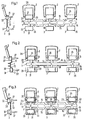
- Each band-like sealing strip has a coupling strip 1.
- closures are fastened to the coupling strip 1 and consist of an upper part 2 and a lower part 3.
- One-piece closures can also be attached to the coupling strip 1.
- Each closure part 2, 3 has a stop part designed as a cap 21, 31.
- the caps 21, 31 do not have to be part of a closure; they can also belong to another stop element.
- at least one of the walls of each cap 21, 31 is angled and connected to the coupling strip 1.
- Each of the caps 21, 31 has a face wall 22, 32, two side walls 23, 33, a wall 24, 34 facing the other cap 31, 21 and a further wall 25, 35 facing away.
- Each cap 21, 31 can be assembled from two cap-shaped parts.
- a closure flap 26 is articulated in the cap 21 belonging to the upper part 2. The opening in the closure flap 26 engages over the cap 31 of the lower part 3 when the closure is in the closed position. Other types of closure flaps and their attachment to the cap are possible.
- spring elements can be provided in the cap.
- Folding tongues 27, 37 are formed in the extension of the side walls 23, 33. In the exemplary embodiment, an impact tongue 27, 37 is provided for each side wall 23, 33, which ends in a tip at the free end.
- a tongue 28 is recessed from the wall 24 of the cap 21 facing the coupling strip 1 and angled once.
- the tongue 28 merges into a connecting web 11 to the coupling strip 1.
- the view wall 32 of the cap 31 is extended like a tongue into the connecting web 12 and slightly angled beyond the wall 34 facing the upper part 2.
- the connecting webs 11, 12 provided in the extension of the tongues 28, 38 lie in one plane with the coupling strip 1.
- the connecting webs 11, 12 are provided in the axis of symmetry of the upper and lower part 2, 3.
- the upper part 2 is severed at the transition from the tongue 28 into the connecting web 11; the lower part 3 directly in the plane of the wall 34.
- the tongue 28 remains attached to the upper part 2; the lower part 3 has a slot in the wall 34.
- the tongue 28 is guided in the slot, which stabilizes the closure.
- FIG. 2 shows, it is possible to bend the tongues 28, 38 several times before they pass into the connecting web 11, 12.
- the cap 21, 31 is also intended to present a complete wall, for example a complete wall 24, 34 facing the coupling strip 1, in the area covered after the closure has been closed.
- the connecting webs 11, 12 and the tongues 28, 38 it is also possible to design the connecting webs 11, 12 and the tongues 28, 38 not in a flat, but in a multidimensional manner, in particular to fold them up at the longitudinal edges.
- FIG. 3 shows, a plurality of connecting webs 11 with an additional tongue 28 from the same cap 21 to the coupling strip 1 are also possible.
- the connecting webs and the tongues can be performed on different levels.
- the coupling strip 1 with the connecting webs 11, 12 and the caps 21, 31 is made of the same material, in FIG. 3 with the lower part of the caps 21, 31. It is designed as a strip in the area 13 of the caps 21, 31. In the connection area of the caps 21, 31, the coupling strip is provided with holes, warts 14 or the like. The holes, warts 14 or the like serve for the engagement of feed devices which are part of the striking machine and move the entire sealing strip step by step into the striking machine.
- the coupling strip 1 is divided into two parallel legs 15, spaced apart from one another - FIGS. 1 and 3. This configuration of the coupling strip 1 increases its torsional rigidity. In another way - FIG. 2 - the torsional stiffness can be increased if the coupling strip 1 is folded up at the edges 16 between the connecting webs 11, 12.
Landscapes
- Engineering & Computer Science (AREA)
- Mechanical Engineering (AREA)
- Life Sciences & Earth Sciences (AREA)
- Forests & Forestry (AREA)
- Control And Other Processes For Unpacking Of Materials (AREA)
- Cartons (AREA)
- Package Frames And Binding Bands (AREA)
- Closures For Containers (AREA)
- Sealing Of Jars (AREA)
- Basic Packing Technique (AREA)
Claims (9)
Priority Applications (1)
| Application Number | Priority Date | Filing Date | Title |
|---|---|---|---|
| AT83100379T ATE35236T1 (de) | 1982-02-27 | 1983-01-18 | Bandartiger verschlussstreifen. |
Applications Claiming Priority (2)
| Application Number | Priority Date | Filing Date | Title |
|---|---|---|---|
| DE8205544U DE8205544U1 (de) | 1982-02-27 | 1982-02-27 | Bandartiger Verschlussstreifen |
| DE8205544U | 1982-02-27 |
Publications (3)
| Publication Number | Publication Date |
|---|---|
| EP0087563A2 EP0087563A2 (fr) | 1983-09-07 |
| EP0087563A3 EP0087563A3 (en) | 1986-05-14 |
| EP0087563B1 true EP0087563B1 (fr) | 1988-06-22 |
Family
ID=6737535
Family Applications (1)
| Application Number | Title | Priority Date | Filing Date |
|---|---|---|---|
| EP19830100379 Expired EP0087563B1 (fr) | 1982-02-27 | 1983-01-18 | Bande à fermetures |
Country Status (4)
| Country | Link |
|---|---|
| US (1) | US4546878A (fr) |
| EP (1) | EP0087563B1 (fr) |
| AT (1) | ATE35236T1 (fr) |
| DE (2) | DE8205544U1 (fr) |
Families Citing this family (1)
| Publication number | Priority date | Publication date | Assignee | Title |
|---|---|---|---|---|
| SE467270B (sv) * | 1988-10-12 | 1992-06-22 | Diab Barracuda Ab | Bandade faestdon, saerskilt foer hopfaestande av plastfilmer och liknande med foerstaerkningsnaet till maskeringsnaet, saett att framstaella faestdonen samt maskin foer montering av desamma |
Family Cites Families (14)
| Publication number | Priority date | Publication date | Assignee | Title |
|---|---|---|---|---|
| US1080551A (en) * | 1912-02-19 | 1913-12-09 | Ralph W Hartwell | Ice-box. |
| US1276852A (en) * | 1917-03-09 | 1918-08-27 | Icy Hot Bottle Company | Lunch kit. |
| US3147086A (en) * | 1962-03-08 | 1964-09-01 | Thomas & Betts Co Inc | Link for series of connectors |
| GB1226577A (fr) * | 1968-03-29 | 1971-03-31 | ||
| DE1910580C3 (de) * | 1969-03-01 | 1982-05-13 | Schmale GmbH & Co KG, 5880 Lüdenscheid | Einer Anschlagmaschine zuführbare bandartiger Verschlußstreifen |
| US3774756A (en) * | 1969-10-22 | 1973-11-27 | Textron Inc | Molded plastic snap fastener for strip of components therefore |
| JPS5033525A (fr) * | 1973-07-31 | 1975-03-31 | ||
| DE2405998C2 (de) * | 1974-02-08 | 1981-10-15 | Schmale GmbH & Co KG, 5880 Lüdenscheid | Bandförmiges Werkstück für eine Anschlagmaschine |
| DE2422128C3 (de) * | 1974-05-08 | 1981-12-24 | Schmale GmbH & Co KG, 5880 Lüdenscheid | Verschlußoberteil und/oder Verschlußunterteil für kastenförmige Behälter |
| DE7531968U (de) * | 1975-10-08 | 1976-03-04 | Gebr. Maissenbacher, 7530 Pforzheim | Verschlussbeschlag fuer etuis, kaesten und aehnliche behaeltnisse |
| DE7623139U1 (de) * | 1976-07-22 | 1976-11-18 | Schmale & Co, 5880 Luedenscheid | Verschluss mit federnder zuhaltung |
| DE2659150C3 (de) * | 1976-12-28 | 1981-10-29 | Schmale GmbH & Co KG, 5880 Lüdenscheid | Mit Beschlägen versehener Leitstreifen für eine Anschlagmaschine |
| US4165673A (en) * | 1978-04-03 | 1979-08-28 | Amp Incorporated | Metal stamped and formed screw |
| DE2904503C2 (de) * | 1979-02-07 | 1985-10-24 | Schmale GmbH & Co KG, 5880 Lüdenscheid | Verschluß für kastenförmige Behälter |
-
1982
- 1982-02-27 DE DE8205544U patent/DE8205544U1/de not_active Expired
-
1983
- 1983-01-18 AT AT83100379T patent/ATE35236T1/de not_active IP Right Cessation
- 1983-01-18 EP EP19830100379 patent/EP0087563B1/fr not_active Expired
- 1983-01-18 DE DE8383100379T patent/DE3377116D1/de not_active Expired
- 1983-02-28 US US06/470,283 patent/US4546878A/en not_active Expired - Lifetime
Also Published As
| Publication number | Publication date |
|---|---|
| EP0087563A2 (fr) | 1983-09-07 |
| US4546878A (en) | 1985-10-15 |
| EP0087563A3 (en) | 1986-05-14 |
| DE3377116D1 (en) | 1988-07-28 |
| ATE35236T1 (de) | 1988-07-15 |
| DE8205544U1 (de) | 1982-05-13 |
Similar Documents
| Publication | Publication Date | Title |
|---|---|---|
| DE19605080B4 (de) | Transportbehälter mit lösbar verrastbaren Klappwänden | |
| DE69501267T2 (de) | Zuschnitt zur Herstellung einer leicht zu öffnenden amerikanischen Schachtel, sowie so hergestellte Schachtel | |
| DE1586566C3 (de) | Zuschnitt für einen Faltkarton zum Umhüllen einer Anzahl von Dosen mit ausgesparten Enden | |
| DE7817947U1 (de) | Rollenbahn | |
| EP0143299A2 (fr) | Elément de protection de coins ou de bords | |
| WO2007104543A1 (fr) | Insert à claire-voie | |
| EP1281636A2 (fr) | Etui à cigarettes à couvercle rabattable | |
| DE3909898C2 (fr) | ||
| EP0087563B1 (fr) | Bande à fermetures | |
| DE2033724C3 (de) | Zusammenlegbare Kiste | |
| DE8702930U1 (de) | Flaschenkasten | |
| DE2926621C2 (de) | Bauelement zur Herstellung ptismatischer Wandkonstruktionen | |
| DE2422128C3 (de) | Verschlußoberteil und/oder Verschlußunterteil für kastenförmige Behälter | |
| EP0215265A2 (fr) | Emballage en forme de boîte à montage rapide pour des marchandises sensibles à la pression, en particulier pour les produits alimentaires | |
| EP0388656A2 (fr) | Tiroir métallique | |
| DE2405998A1 (de) | Bandfoermiges werkstueck fuer eine anschlagmaschine | |
| DE202006004359U1 (de) | Gitterfacheinsatz | |
| DE69304580T2 (de) | Trennwand für Waren | |
| DE9307034U1 (de) | Verkaufspackung für Handarbeitsnadeln, wie Stricknadeln | |
| DE2517086B2 (de) | Aus gepreßten ebenen Formteilen zusammengesetzte stapelbare Kiste | |
| DE2326019A1 (de) | Verpackungspolster | |
| DE7534365U (de) | Abgabevorrichtung zur Einzelentnahme von in einem Stapelschacht angeordneten im wesentlichen prismatischen Gegenstaenden | |
| DE9210342U1 (de) | Kunststoffkiste mit Aufnahmefläche für ein entnehmbares Etikett | |
| DE9307033U1 (de) | Verkaufspackung für Handarbeitsnadeln, wie Stricknadeln | |
| DE8506767U1 (de) | Verpackungseinsatz mit Faechern zum Halten von vereinzelten Schrauben in einem Umkarton |
Legal Events
| Date | Code | Title | Description |
|---|---|---|---|
| PUAI | Public reference made under article 153(3) epc to a published international application that has entered the european phase |
Free format text: ORIGINAL CODE: 0009012 |
|
| AK | Designated contracting states |
Designated state(s): AT CH DE FR GB IT LI NL SE |
|
| PUAL | Search report despatched |
Free format text: ORIGINAL CODE: 0009013 |
|
| AK | Designated contracting states |
Kind code of ref document: A3 Designated state(s): AT CH DE FR GB IT LI NL SE |
|
| 17P | Request for examination filed |
Effective date: 19860811 |
|
| 17Q | First examination report despatched |
Effective date: 19870730 |
|
| GRAA | (expected) grant |
Free format text: ORIGINAL CODE: 0009210 |
|
| AK | Designated contracting states |
Kind code of ref document: B1 Designated state(s): AT CH DE FR GB IT LI NL SE |
|
| PG25 | Lapsed in a contracting state [announced via postgrant information from national office to epo] |
Ref country code: NL Effective date: 19880622 |
|
| REF | Corresponds to: |
Ref document number: 35236 Country of ref document: AT Date of ref document: 19880715 Kind code of ref document: T |
|
| PG25 | Lapsed in a contracting state [announced via postgrant information from national office to epo] |
Ref country code: SE Effective date: 19880630 |
|
| GBT | Gb: translation of ep patent filed (gb section 77(6)(a)/1977) | ||
| REF | Corresponds to: |
Ref document number: 3377116 Country of ref document: DE Date of ref document: 19880728 |
|
| ET | Fr: translation filed | ||
| ITF | It: translation for a ep patent filed | ||
| NLV1 | Nl: lapsed or annulled due to failure to fulfill the requirements of art. 29p and 29m of the patents act | ||
| PG25 | Lapsed in a contracting state [announced via postgrant information from national office to epo] |
Ref country code: AT Effective date: 19890118 |
|
| PG25 | Lapsed in a contracting state [announced via postgrant information from national office to epo] |
Ref country code: LI Effective date: 19890131 Ref country code: CH Effective date: 19890131 |
|
| PLBE | No opposition filed within time limit |
Free format text: ORIGINAL CODE: 0009261 |
|
| STAA | Information on the status of an ep patent application or granted ep patent |
Free format text: STATUS: NO OPPOSITION FILED WITHIN TIME LIMIT |
|
| 26N | No opposition filed | ||
| REG | Reference to a national code |
Ref country code: CH Ref legal event code: PL |
|
| ITTA | It: last paid annual fee | ||
| REG | Reference to a national code |
Ref country code: GB Ref legal event code: IF02 |
|
| PGFP | Annual fee paid to national office [announced via postgrant information from national office to epo] |
Ref country code: FR Payment date: 20020128 Year of fee payment: 20 |
|
| PGFP | Annual fee paid to national office [announced via postgrant information from national office to epo] |
Ref country code: DE Payment date: 20020129 Year of fee payment: 20 |
|
| PGFP | Annual fee paid to national office [announced via postgrant information from national office to epo] |
Ref country code: GB Payment date: 20020215 Year of fee payment: 20 |
|
| PG25 | Lapsed in a contracting state [announced via postgrant information from national office to epo] |
Ref country code: GB Free format text: LAPSE BECAUSE OF EXPIRATION OF PROTECTION Effective date: 20030117 |
|
| REG | Reference to a national code |
Ref country code: GB Ref legal event code: PE20 Effective date: 20030117 |