EP0087614A2 - Optisches Element - Google Patents
Optisches Element Download PDFInfo
- Publication number
- EP0087614A2 EP0087614A2 EP83101125A EP83101125A EP0087614A2 EP 0087614 A2 EP0087614 A2 EP 0087614A2 EP 83101125 A EP83101125 A EP 83101125A EP 83101125 A EP83101125 A EP 83101125A EP 0087614 A2 EP0087614 A2 EP 0087614A2
- Authority
- EP
- European Patent Office
- Prior art keywords
- layers
- layer
- oxide
- fluoride
- optical element
- Prior art date
- Legal status (The legal status is an assumption and is not a legal conclusion. Google has not performed a legal analysis and makes no representation as to the accuracy of the status listed.)
- Granted
Links
Images


Classifications
-
- C—CHEMISTRY; METALLURGY
- C03—GLASS; MINERAL OR SLAG WOOL
- C03C—CHEMICAL COMPOSITION OF GLASSES, GLAZES OR VITREOUS ENAMELS; SURFACE TREATMENT OF GLASS; SURFACE TREATMENT OF FIBRES OR FILAMENTS MADE FROM GLASS, MINERALS OR SLAGS; JOINING GLASS TO GLASS OR OTHER MATERIALS
- C03C17/00—Surface treatment of glass, not in the form of fibres or filaments, by coating
- C03C17/34—Surface treatment of glass, not in the form of fibres or filaments, by coating with at least two coatings having different compositions
- C03C17/36—Surface treatment of glass, not in the form of fibres or filaments, by coating with at least two coatings having different compositions at least one coating being a metal
- C03C17/3602—Surface treatment of glass, not in the form of fibres or filaments, by coating with at least two coatings having different compositions at least one coating being a metal the metal being present as a layer
- C03C17/3649—Surface treatment of glass, not in the form of fibres or filaments, by coating with at least two coatings having different compositions at least one coating being a metal the metal being present as a layer made of metals other than silver
-
- C—CHEMISTRY; METALLURGY
- C03—GLASS; MINERAL OR SLAG WOOL
- C03C—CHEMICAL COMPOSITION OF GLASSES, GLAZES OR VITREOUS ENAMELS; SURFACE TREATMENT OF GLASS; SURFACE TREATMENT OF FIBRES OR FILAMENTS MADE FROM GLASS, MINERALS OR SLAGS; JOINING GLASS TO GLASS OR OTHER MATERIALS
- C03C17/00—Surface treatment of glass, not in the form of fibres or filaments, by coating
- C03C17/34—Surface treatment of glass, not in the form of fibres or filaments, by coating with at least two coatings having different compositions
- C03C17/3411—Surface treatment of glass, not in the form of fibres or filaments, by coating with at least two coatings having different compositions with at least two coatings of inorganic materials
- C03C17/3429—Surface treatment of glass, not in the form of fibres or filaments, by coating with at least two coatings having different compositions with at least two coatings of inorganic materials at least one of the coatings being a non-oxide coating
- C03C17/3447—Surface treatment of glass, not in the form of fibres or filaments, by coating with at least two coatings having different compositions with at least two coatings of inorganic materials at least one of the coatings being a non-oxide coating comprising a halide
- C03C17/3452—Surface treatment of glass, not in the form of fibres or filaments, by coating with at least two coatings having different compositions with at least two coatings of inorganic materials at least one of the coatings being a non-oxide coating comprising a halide comprising a fluoride
-
- C—CHEMISTRY; METALLURGY
- C03—GLASS; MINERAL OR SLAG WOOL
- C03C—CHEMICAL COMPOSITION OF GLASSES, GLAZES OR VITREOUS ENAMELS; SURFACE TREATMENT OF GLASS; SURFACE TREATMENT OF FIBRES OR FILAMENTS MADE FROM GLASS, MINERALS OR SLAGS; JOINING GLASS TO GLASS OR OTHER MATERIALS
- C03C17/00—Surface treatment of glass, not in the form of fibres or filaments, by coating
- C03C17/34—Surface treatment of glass, not in the form of fibres or filaments, by coating with at least two coatings having different compositions
- C03C17/3411—Surface treatment of glass, not in the form of fibres or filaments, by coating with at least two coatings having different compositions with at least two coatings of inorganic materials
- C03C17/3429—Surface treatment of glass, not in the form of fibres or filaments, by coating with at least two coatings having different compositions with at least two coatings of inorganic materials at least one of the coatings being a non-oxide coating
- C03C17/3464—Surface treatment of glass, not in the form of fibres or filaments, by coating with at least two coatings having different compositions with at least two coatings of inorganic materials at least one of the coatings being a non-oxide coating comprising a chalcogenide
- C03C17/347—Surface treatment of glass, not in the form of fibres or filaments, by coating with at least two coatings having different compositions with at least two coatings of inorganic materials at least one of the coatings being a non-oxide coating comprising a chalcogenide comprising a sulfide or oxysulfide
-
- C—CHEMISTRY; METALLURGY
- C03—GLASS; MINERAL OR SLAG WOOL
- C03C—CHEMICAL COMPOSITION OF GLASSES, GLAZES OR VITREOUS ENAMELS; SURFACE TREATMENT OF GLASS; SURFACE TREATMENT OF FIBRES OR FILAMENTS MADE FROM GLASS, MINERALS OR SLAGS; JOINING GLASS TO GLASS OR OTHER MATERIALS
- C03C17/00—Surface treatment of glass, not in the form of fibres or filaments, by coating
- C03C17/34—Surface treatment of glass, not in the form of fibres or filaments, by coating with at least two coatings having different compositions
- C03C17/3411—Surface treatment of glass, not in the form of fibres or filaments, by coating with at least two coatings having different compositions with at least two coatings of inorganic materials
- C03C17/3429—Surface treatment of glass, not in the form of fibres or filaments, by coating with at least two coatings having different compositions with at least two coatings of inorganic materials at least one of the coatings being a non-oxide coating
- C03C17/3464—Surface treatment of glass, not in the form of fibres or filaments, by coating with at least two coatings having different compositions with at least two coatings of inorganic materials at least one of the coatings being a non-oxide coating comprising a chalcogenide
- C03C17/3476—Surface treatment of glass, not in the form of fibres or filaments, by coating with at least two coatings having different compositions with at least two coatings of inorganic materials at least one of the coatings being a non-oxide coating comprising a chalcogenide comprising a selenide or telluride
-
- C—CHEMISTRY; METALLURGY
- C03—GLASS; MINERAL OR SLAG WOOL
- C03C—CHEMICAL COMPOSITION OF GLASSES, GLAZES OR VITREOUS ENAMELS; SURFACE TREATMENT OF GLASS; SURFACE TREATMENT OF FIBRES OR FILAMENTS MADE FROM GLASS, MINERALS OR SLAGS; JOINING GLASS TO GLASS OR OTHER MATERIALS
- C03C17/00—Surface treatment of glass, not in the form of fibres or filaments, by coating
- C03C17/34—Surface treatment of glass, not in the form of fibres or filaments, by coating with at least two coatings having different compositions
- C03C17/36—Surface treatment of glass, not in the form of fibres or filaments, by coating with at least two coatings having different compositions at least one coating being a metal
-
- G—PHYSICS
- G02—OPTICS
- G02B—OPTICAL ELEMENTS, SYSTEMS OR APPARATUS
- G02B1/00—Optical elements characterised by the material of which they are made; Optical coatings for optical elements
- G02B1/10—Optical coatings produced by application to, or surface treatment of, optical elements
- G02B1/11—Anti-reflection coatings
- G02B1/113—Anti-reflection coatings using inorganic layer materials only
- G02B1/115—Multilayers
-
- G—PHYSICS
- G02—OPTICS
- G02B—OPTICAL ELEMENTS, SYSTEMS OR APPARATUS
- G02B13/00—Optical objectives specially designed for the purposes specified below
- G02B13/14—Optical objectives specially designed for the purposes specified below for use with infrared or ultraviolet radiation
-
- G—PHYSICS
- G02—OPTICS
- G02B—OPTICAL ELEMENTS, SYSTEMS OR APPARATUS
- G02B5/00—Optical elements other than lenses
- G02B5/20—Filters
- G02B5/208—Filters for use with infrared or ultraviolet radiation, e.g. for separating visible light from infrared and/or ultraviolet radiation
Definitions
- the invention relates to optical elements which are based on an infrared-transmissive base made of a material from the group: germanium, zinc selenide, zinc sulfide and chalcogenide glasses, a system consisting of several infrared-transmissive optically active thin layers made of substances from the group: germanium, zinc selenide, zinc sulfide, chalcogenide glasses, thorium fluoride, yttrium fluoride and have praseodymium fluoride.
- Such elements are e.g. in the form of infrared transmissive lenses with anti-reflective coating, used as a narrow band transmission filter and as a polarization filter for infrared.
- the adhesion of the layer systems to the underlay and the layers to one another is often still a problem; in the case of infrared layer systems in particular because both the above-mentioned infrared-transparent substrates and the layer materials on the one hand are more or less sensitive to air humidity and oxidation and on the other hand the known infrared-transparent layer materials often show high layer tensions.
- Adhesive layers which are arranged between the base and the layer system and are so thin that the adhesive layers themselves do not interfere with the function of the optical element.
- Adhesive layers made of oxides in particular have already been used many times for optical elements for the visible spectral range.
- the object of the present invention is to provide for optical elements of the type mentioned at the outset (ie limited to the documents and layer materials mentioned there), such as better adhesion of the layer system to the base and, in a further embodiment of the invention, also between the individual layers of the system can be reached among themselves. It has been found that the first main task is solved perfectly by placing an intermediate layer of at most 100 nm thick made from a material from the group: hafnium oxide, yttrite oxide and scandium oxide between the substrate and the optically active layer adjacent to it. For better bonding of the layers among themselves, it is recommended to provide an intermediate layer of one of the oxides mentioned between them.
- Tables 1 and 2 correspond to the exemplary embodiments in FIGS. 1 and 2.
- the last three adhesive layer materials mentioned have a special position among the oxides, which are generally known as adhesive layer materials, because of their particular suitability for infrared optics. Their equivalence for the purpose of the invention goes so far that they are in the exemplary embodiments can be interchanged with one another without changing the properties of the layer system significantly; in this way, new exemplary embodiments of the invention are obtained.
- the refractive indices of the layers produced from these materials can, however, deviate slightly from the values given, depending on the production process, but these deviations can easily be taken into account by the person skilled in the art when calculating the layer systems.
- Optical thickness of a layer is understood to mean the product of the refractive index of the layer material and the actual layer thickness; where there is no explicit reference to “optical thickness”, the actual layer thickness, measured in ⁇ m or nm, is meant.
- an adhesion-promoting layer is not only installed between the base and the layer system, but also always between the individual optically active layers. However, the latter is not absolutely necessary in all cases. In many cases, it is sufficient to arrange an adhesive layer only between the base and the layer system or then to provide adhesion-promoting layers only between certain individual layers of the system; in the given case this depends on the number of layers of the system and the layer materials.
Landscapes
- Chemical & Material Sciences (AREA)
- Materials Engineering (AREA)
- Engineering & Computer Science (AREA)
- Chemical Kinetics & Catalysis (AREA)
- General Chemical & Material Sciences (AREA)
- Geochemistry & Mineralogy (AREA)
- Life Sciences & Earth Sciences (AREA)
- Organic Chemistry (AREA)
- Physics & Mathematics (AREA)
- Inorganic Chemistry (AREA)
- General Physics & Mathematics (AREA)
- Optics & Photonics (AREA)
- Joining Of Glass To Other Materials (AREA)
- Surface Treatment Of Optical Elements (AREA)
Abstract
Description
- Die Erfindung betrifft optische Elemente, welche auf einer infrarotdurchlässigen Unterlage aus einem Material der Gruppe: Germanium, Zinkselenid, Zinksulfid und Chalkogenidgläser, ein System aus mehreren infrarotdurchlässigen optisch wirksamen dünnen Schichten aus Substanzen der Gruppe: Germanium, Zinkselenid, Zinksulfid, Chalkogenidgläser, Thoriumfluorid, Yttriumfluorid und Praseodymfluorid aufweisen.
- Derartige Elemente werden z.B. in Form von infrarotdurchlässigen Linsen mit reflexionsvermindemdem Belag, als Schmalbandtransmissionsfilter und als Polarisationsfilter für Infrarot verwendet. Dabei stellt die Haftung der Schichtsysteme auf den Unterlagen und der Schichten untereinander häufig immer noch ein Problem dar; bei Infrarotschichtsystem insbesondere deshalb, weil sowohl die genannten infrarotdurchlässigen Unterlagen als auch die Schichtmaterialien einerseits gegen Luftfeuchtigkeit und Oxydation mehr oder weniger empfindlich sind und andererseits die bekannten infrarotdurchlässigen Schichtmaterialien oft hohe Schichtspannungen zeigen.
- Die Haftung von Schichten auf Unterlagen durch sogenannte Haftschichten zu verbessern, die zwischen der Unterlage und dem Schichtsystem angeordnet und so dünn sind, dass die Haftschichten selbst die Funktion des optischen Elementes nicht stören, ist bekannt. Für optische Elemente für den sichtbaren Spektralbereich sind vor allem Haftschichten aus Oxiden schon vielfach verwendet worden.
- Schwieriger ist die Situation im Falle optischer Elemente für den IR-Bereich, insbesondere für einige neuere Anwendungen, bei denen auf IRdurchlässigen Unterlagen Schichtsysteme aus sehr vielen - bis zu 50 - Einzelschichten aufgebracht werden. Der Grund für die Schwierigkeit liegt darin, dass die als Haftschichten in Frage kommenden Materialien meist eine verhältnismässig starke Absorption besitzen, letzteres besonders dann, wenn sie Feuchtigkeit aufgencmren haben und damit H20-Absorptionsbanden aufweisen. Ganz besonders ins Gewicht fallen Absoptionsverluste bei Laserspiegeln, die bei einem möglichst hohen Reflexionsvermögen eine möglichst geringe Absorption besitzen müssen, um hohen Ausgangsintensitäten des Laserstrahls standzuhalten.
- Es ist bekannt bei auf Germaniumunterlagen aufzubringenden IR-Schichtsystemen eine bessere Haftung zwischen der Unterlage und dem Schichtsystem dadurch zu erreichen, dass eine Haftschicht aus Germanium, die nur wenige Atomlagen dick zu sein braucht, eingeschaltet wird. Ferner bekannt sind für optische Elemente auch Schutzschichten, welche aus dem Dampf siliziumorganischer Verbindungen mittels einer elektrischen Glimmentladung auf den zu schützenden Flächen niedergeschlagen werden.
- Die vorliegende Erfindung stellt sich die Aufgabe, für optische Elemente der eingangs genannten Art (d.h. beschränkt auf die dort erwähnten Unterlagen und Schichtmaterialien) anzugeben, wie eine besser Haftung des Schichtsystems auf der Unterlage und in weiterer Ausgestaltung der Erfindung auch zwischen den einzelnen Schichten des Systems unter sich erreicht werden kann. Es wurde gefunden, dass erstgenannte Hauptaufgabe einwandfrei dadurch gelöst wird, dass zwischen der Unterlage und der dieser benachbarten optisch wirksamen Schicht eine höchstens 100 nm dicke Zwischenschicht aus einem Material der Gruppe: Hafniumoxid, Yttritumxid und Scandiumoxid angeordnet wird. Zur besseren Bindung der Schichten unter sich wird empfohlen, auch zwischen diesen eine Zwischenschicht aus einem der genannten Oxide vorzusehen.
- Nachfolgend werden einige Ausführungsbeispiele der Erfindung anhand der anliegenden Zeichnungen näher beschrieben.
-
- Figur 1 schematisch den Aufbau eines optischen Elementes bestehend aus einer Unterlage aus einem Chalkogenidglas und einen darauf aufgebrachten schmalbandigen reflexionsvermindernden Schichtsystem, zusammen mit der Reflexionskurve dieses optischen Elementes;
- Figur 2 den schematischen Schichtaufbau eines optischen Elementes mit Germaniumunterlage und Breitbandreflexionsverminderung zusammen mit der entsprechenden Reflexionskurve.
- In den untenstehenden Tabellen sind die Materialien, Brechwerte und optischen Dicken verschiedener Ausführungsbeispiele der Erfindung angegeben, ebenso die laufende Nummer jeder Schicht, wobei die an Luft angrenzende mit Nummer 1 bezeichnet wurde, sodass also die an die Unterlage anliegende Schicht die höchste laufende Nummer aufweist. Die Tabellen 1 und 2 entsprechen den Ausführungsbeispielen der Figuren 1 und 2.
- Zu den verwendeten Schichtmaterialien sei noch folgendes bemerkt: die niederbrechenden Materialien Thoriumfluorid (ThF4) Yttriumfluorid (YF3) und Praseodymfluorid (PrF3) weisen fast gleiche Brechwerte auf (1,35 bzw. 1,35 bzw. 1,40 bei Lambda = 10 µm) und können in den vorerwähnten Beispielen einander ersetzen. Dasselbe gilt auch für die haftvermittelnden Schichten Hafniumoxid (HfO2, n = 1.80) Yttriumoxid (Y203, n = 1.7) und Scandiumaxid (Sc2O3, n = 1.75). Die drei letztgenannten Haftschichtmaterialien besitzen wegen ihrer besonderen Eignung für die Infrarot-Optik eine Sonderstellung unter den ansich allgemein als Haftschichtmaterialien bekannten Oxiden. Ihre Gleichwertigkeit für den Zweck der Erfindung geht so weit, dass sie in den Ausführungsbeispielen beliebig gegeneinander ausgetauscht werden können, ohne dass die Eigenschaften des Schichtsystems dadurch wesentlich geändert werden; man erhält also auf diese Weise neue Ausführungsbeispiele der Erfindung. Die Brechwerte der aus diesen Materialien hergestellten Schichten können aber je nach Herstellungsverfahren von den angegebenen Werten ein wenig abweichen, jedoch können diese Abweichungen bei der Berechnung der Schichtsysteme durch den Fachmann leicht berücksichtigt werden.
- Unter Chalkogenidgläsern werden im Rahmen der vorliegenden Erfindung Gläser verstanden, wie sie in
- i) A.R. Hilton, D.J. Hayes, M.D. Rechtin Infrared Absorption of some high purity Chalcogenide glasses. J. Noncryst. Solids 17, 319 (1975)
- ii) A.R. Hilton, C.E. Jones, M. Brau Non oxide IVA-VA-VIA chalcogenide glasses Part I, Part II, Part III Phys. Chem. of Glasses 7, 105, 112, 116 (1966)
- Unter "ontischer Dicke" einer Schicht wird das Produkt aus dem Brechwert des Schichtmaterials und der wirklichen Schichtdicke verstanden; wo nicht ausdrücklich von "optischer Dicke" gesprochen wird, ist die wirkliche Schichtdicke, gemessen in µm oder nm, gemeint.


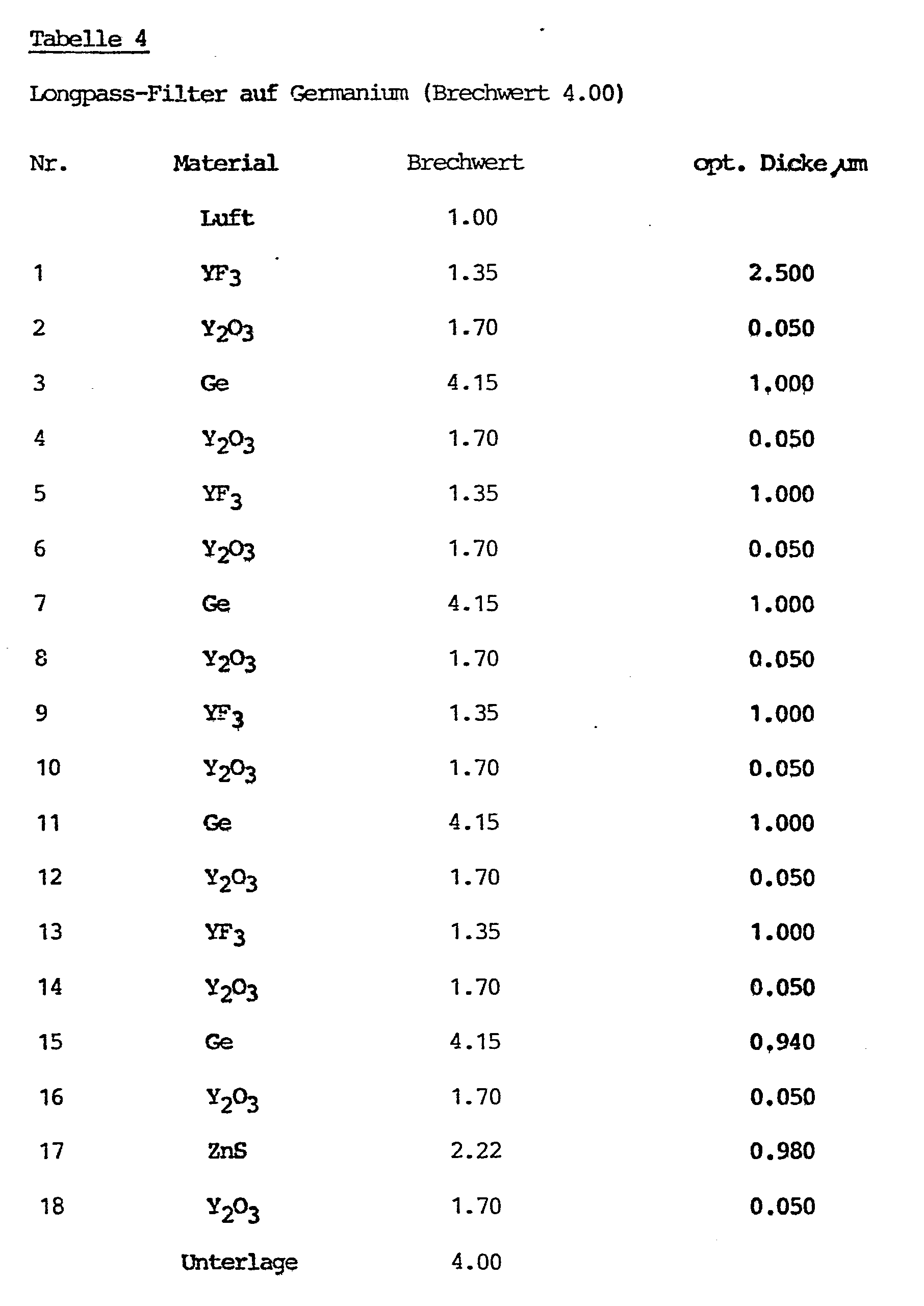

- In den beschriebenen Ausführungsbeispielen ist nicht nur zwischen der Unterlage und dem Schichtsystem eine haftvermittelnde Schicht eingebaut sondern stets auch zwischen den einzelnen optisch wirksamen Schichten. Letzteres ist jedoch nicht unbedingt in allen Fällen notwendig. Vielfach genügt es, eine Haftschicht lediglich zwischen Unterlage und Schichtsystem anzuordnen oder dann haftvermittelnde Schichten nur zwischen bestimmten Einzelschichten des Systems vorzusehen; dies hängt im gegebenen Fall von der Schichtzahl des Systems und von den Schichtmaterialien ab.
beschrieben worden sind.
Claims (3)
Applications Claiming Priority (2)
| Application Number | Priority Date | Filing Date | Title |
|---|---|---|---|
| CH1234/82 | 1982-03-01 | ||
| CH1234/82A CH658522A5 (de) | 1982-03-01 | 1982-03-01 | Optisches element. |
Publications (3)
| Publication Number | Publication Date |
|---|---|
| EP0087614A2 true EP0087614A2 (de) | 1983-09-07 |
| EP0087614A3 EP0087614A3 (en) | 1986-08-13 |
| EP0087614B1 EP0087614B1 (de) | 1988-07-06 |
Family
ID=4205614
Family Applications (1)
| Application Number | Title | Priority Date | Filing Date |
|---|---|---|---|
| EP83101125A Expired EP0087614B1 (de) | 1982-03-01 | 1983-02-07 | Optisches Element |
Country Status (4)
| Country | Link |
|---|---|
| US (1) | US4498728A (de) |
| EP (1) | EP0087614B1 (de) |
| CH (1) | CH658522A5 (de) |
| DE (1) | DE3377297D1 (de) |
Cited By (2)
| Publication number | Priority date | Publication date | Assignee | Title |
|---|---|---|---|---|
| GB2192733A (en) * | 1986-06-18 | 1988-01-20 | Raytheon Co | Impact resistant and tempered optical elements |
| GB2273367A (en) * | 1992-11-30 | 1994-06-15 | Lanarealm Ltd | Optical beam splitter block having refractive index of at least 1-8 |
Families Citing this family (23)
| Publication number | Priority date | Publication date | Assignee | Title |
|---|---|---|---|---|
| US4770479A (en) * | 1985-07-01 | 1988-09-13 | Raytheon Company | Optical elements having buried layers and method of manufacture |
| US4794053A (en) * | 1985-07-01 | 1988-12-27 | Raytheon Company | Optical elements having buried layers |
| US4772080A (en) * | 1985-07-01 | 1988-09-20 | Raytheon Company | Optical elements having buried layers and method of manufacture |
| US4995684A (en) * | 1986-06-18 | 1991-02-26 | Raytheon Company | Impact resistant and tempered optical elements |
| US4907846A (en) * | 1987-11-20 | 1990-03-13 | Raytheon Company | Thick, impact resistant antireflection coatings for IR transparent optical elements |
| US5486949A (en) * | 1989-06-20 | 1996-01-23 | The Dow Chemical Company | Birefringent interference polarizer |
| US5067781A (en) * | 1989-11-21 | 1991-11-26 | Raytheon Company | Optical elements and method of manufacture |
| US5120602A (en) * | 1990-02-02 | 1992-06-09 | Raytheon Company | Optical elements and method of manufacture |
| JP3249992B2 (ja) * | 1990-12-25 | 2002-01-28 | ミノルタ株式会社 | シリコン基板またはゲルマニウム基板用反射防止膜 |
| CH695281A5 (de) * | 1993-04-02 | 2006-02-28 | Balzers Hochvakuum | Verfahren zur Herstellung eines Filters, danach hergestellte optische Schicht, optisches Bauelement mit einer derartigen Schicht und Braeunungsanlage mit einem solchen Element. |
| US5814367A (en) | 1993-08-13 | 1998-09-29 | General Atomics | Broadband infrared and signature control materials and methods of producing the same |
| US6235105B1 (en) | 1994-12-06 | 2001-05-22 | General Atomics | Thin film pigmented optical coating compositions |
| WO2006081006A2 (en) * | 2004-12-21 | 2006-08-03 | Corning Incorporated | Light polarizing products and method of making same |
| DE602004023743D1 (de) | 2004-12-21 | 2009-12-03 | Corning Inc | Lichtpolarisierende Produkte und Verfahren zur deren Herstellung |
| TR201000297A2 (tr) * | 2010-01-14 | 2011-08-22 | Aselsan Elektron�K Sanay� Ve T�Caret Anon�M ��Rket� | Bir kızılötesi mercek. |
| JP5489824B2 (ja) * | 2010-04-02 | 2014-05-14 | 富士フイルム株式会社 | 反射防止膜及び赤外線用光学素子 |
| JP5730147B2 (ja) * | 2011-06-30 | 2015-06-03 | 日東光学株式会社 | 炭酸ガスレーザー光を透過させる光学素子および反射防止膜 |
| CN103529507B (zh) * | 2012-07-06 | 2016-05-25 | 三菱电机株式会社 | 偏振光相位差板以及激光加工机 |
| WO2014119199A1 (ja) * | 2013-01-31 | 2014-08-07 | ギガフォトン株式会社 | レーザ装置及び極端紫外光生成装置 |
| ES2726812T3 (es) * | 2013-09-16 | 2019-10-09 | Humboldt Univ Zu Berlin | Unidad de láser de cavidad externa que incorpora filtro de interferencia de paso de banda de radiación infrarroja media |
| DE112015004470B4 (de) | 2014-09-30 | 2018-08-23 | Fujifilm Corporation | Antireflexfilm, Linse und Abbildungsvorrichtung |
| GB2561865A (en) * | 2017-04-25 | 2018-10-31 | Univ Of The West Of Scotland | Apparatus and methods for depositing durable optical coatings |
| CN107746187B (zh) * | 2017-09-20 | 2020-09-08 | 湖北森浤光学有限公司 | 一种镀dlc膜的红外硫系玻璃镜片及其制备方法 |
Family Cites Families (6)
| Publication number | Priority date | Publication date | Assignee | Title |
|---|---|---|---|---|
| GB682264A (en) * | 1949-04-18 | 1952-11-05 | Libbey Owens Ford Glass Co | Light transmissive electrically conducting optical articles suitable for use as a lens, a window or windshield, or the like |
| US3468594A (en) * | 1968-06-06 | 1969-09-23 | Westinghouse Electric Corp | Optical apparatus for use in infrared radiation |
| SU451974A1 (ru) * | 1973-05-03 | 1974-11-30 | Предприятие П/Я Р-6681 | Оптическое покрытие |
| SU514259A1 (ru) * | 1973-12-11 | 1976-05-15 | Предприятие П/Я А-1705 | Коротковолновый оптический отрезающий фильтр |
| GB1484284A (en) * | 1975-11-11 | 1977-09-01 | Standard Telephones Cables Ltd | Infra-red filters |
| US4223974A (en) * | 1978-08-02 | 1980-09-23 | American Optical Corporation | Enhanced bonding of silicon oxides and silver by intermediate coating of metal |
-
1982
- 1982-03-01 CH CH1234/82A patent/CH658522A5/de not_active IP Right Cessation
-
1983
- 1983-02-07 DE DE8383101125T patent/DE3377297D1/de not_active Expired
- 1983-02-07 EP EP83101125A patent/EP0087614B1/de not_active Expired
- 1983-03-01 US US06/470,922 patent/US4498728A/en not_active Expired - Lifetime
Cited By (6)
| Publication number | Priority date | Publication date | Assignee | Title |
|---|---|---|---|---|
| GB2192733A (en) * | 1986-06-18 | 1988-01-20 | Raytheon Co | Impact resistant and tempered optical elements |
| FR2605417A1 (fr) * | 1986-06-18 | 1988-04-22 | Raytheon Co | Element optique resistant aux impacts et son procede de fabrication |
| FR2606164A1 (fr) * | 1986-06-18 | 1988-05-06 | Raytheon Co | Elements optiques resistant aux impacts et procede de fabrication de tels elements |
| FR2606165A1 (fr) * | 1986-06-18 | 1988-05-06 | Raytheon Co | Procede pour faire adherer une couche de carbone dur sur une base, notamment pour elements optiques |
| GB2192733B (en) * | 1986-06-18 | 1991-02-06 | Raytheon Co | Impact resistant and tempered optical elements |
| GB2273367A (en) * | 1992-11-30 | 1994-06-15 | Lanarealm Ltd | Optical beam splitter block having refractive index of at least 1-8 |
Also Published As
| Publication number | Publication date |
|---|---|
| US4498728A (en) | 1985-02-12 |
| CH658522A5 (de) | 1986-11-14 |
| DE3377297D1 (en) | 1988-08-11 |
| EP0087614A3 (en) | 1986-08-13 |
| EP0087614B1 (de) | 1988-07-06 |
Similar Documents
| Publication | Publication Date | Title |
|---|---|---|
| EP0087614B1 (de) | Optisches Element | |
| DE60312557T2 (de) | Ein optisches filter | |
| DE3525892C1 (de) | Reflexionsvermindernder Belag fuer ein optisches Element aus organischem Material | |
| EP3243091B1 (de) | Verfahren zur herstellung eines optischen elements mit einem schichtsystem | |
| DE4410275B4 (de) | Verfahren zur Realisierung eines optischen Dünnschicht-Bandpassfilters, ein optisches Dünnschicht-Bandpassfilter, ein optisches Bauelement damit sowie eine Verwendung des Bandpassfilters und eine Bräunungsanlage | |
| DE2336049A1 (de) | Aus abwechselnd hoch- und niederbrechenden oxidschichten aufgebautes verlustarmes, hochreflektierendes vielschichtsystem | |
| EP3158370B1 (de) | Optisches element mit einer reflektierenden beschichtung | |
| DE2341359A1 (de) | Aus einer mehrzahl von einfachen oder zusammengesetzten lambda/4-schichten bestehender reflexionsvermindernder belag | |
| DE2643586B2 (de) | Interferenzreflexionsfilter | |
| DE3009533A1 (de) | Verfahren zur herstellung eines reflexverminderndenmehrschichtenbelages und optischer koerper mit reflexverminderndem mehrschichtenbelag | |
| EP2758826A1 (de) | Optisches bauelement für den ir-bereich mit spannungskompensierter beschichtung | |
| DE202016009136U1 (de) | Reflektierendes Verbundmaterial mit einem Aluminium-Träger und mit einer Silber-Reflexionsschicht | |
| DE1901977A1 (de) | Perot-Fabry-Interferenzfilter | |
| WO2005114266A1 (de) | Hochreflektierender dielektrischer spiegel und verfahren zu dessen herstellung | |
| DE2901675A1 (de) | Reflexionsminderungsbelag mit einer asphaerischen schicht | |
| DE4100831A1 (de) | Breitband-entspiegelungsschichtbelag | |
| CH680214A5 (de) | ||
| DE4100820C2 (de) | Vielschicht-Entspieglungsbelag | |
| DE102004041222A1 (de) | Photonische Kristallstruktur | |
| DE2720742A1 (de) | Mehrschicht-antireflexbelag fuer glassubstrate | |
| DD153511A3 (de) | Interferenzspiegel mit hoher reflexion fuer mehrere spektralbaender | |
| DD219882A1 (de) | Optisches vielschichtsystem | |
| AT300401B (de) | Entspiegelungsbelag | |
| DE2616171C2 (de) | Dreischichtiger Antireflexbelag für optisches Glas | |
| DE10134157B4 (de) | Bauelement mit ultrapräziser Oberfläche und Verfahren zu seiner Herstellung |
Legal Events
| Date | Code | Title | Description |
|---|---|---|---|
| PUAI | Public reference made under article 153(3) epc to a published international application that has entered the european phase |
Free format text: ORIGINAL CODE: 0009012 |
|
| AK | Designated contracting states |
Designated state(s): BE DE FR GB IT NL SE |
|
| 17P | Request for examination filed |
Effective date: 19840229 |
|
| PUAL | Search report despatched |
Free format text: ORIGINAL CODE: 0009013 |
|
| AK | Designated contracting states |
Kind code of ref document: A3 Designated state(s): BE DE FR GB IT NL SE |
|
| 17Q | First examination report despatched |
Effective date: 19870818 |
|
| GRAA | (expected) grant |
Free format text: ORIGINAL CODE: 0009210 |
|
| AK | Designated contracting states |
Kind code of ref document: B1 Designated state(s): BE DE FR GB IT NL SE |
|
| GBT | Gb: translation of ep patent filed (gb section 77(6)(a)/1977) | ||
| REF | Corresponds to: |
Ref document number: 3377297 Country of ref document: DE Date of ref document: 19880811 |
|
| ITF | It: translation for a ep patent filed | ||
| ET | Fr: translation filed | ||
| PLBE | No opposition filed within time limit |
Free format text: ORIGINAL CODE: 0009261 |
|
| STAA | Information on the status of an ep patent application or granted ep patent |
Free format text: STATUS: NO OPPOSITION FILED WITHIN TIME LIMIT |
|
| 26N | No opposition filed | ||
| ITTA | It: last paid annual fee | ||
| EAL | Se: european patent in force in sweden |
Ref document number: 83101125.9 |
|
| PGFP | Annual fee paid to national office [announced via postgrant information from national office to epo] |
Ref country code: SE Payment date: 19990114 Year of fee payment: 17 Ref country code: GB Payment date: 19990114 Year of fee payment: 17 |
|
| PGFP | Annual fee paid to national office [announced via postgrant information from national office to epo] |
Ref country code: DE Payment date: 19990115 Year of fee payment: 17 |
|
| PGFP | Annual fee paid to national office [announced via postgrant information from national office to epo] |
Ref country code: NL Payment date: 19990228 Year of fee payment: 17 |
|
| PGFP | Annual fee paid to national office [announced via postgrant information from national office to epo] |
Ref country code: BE Payment date: 19990416 Year of fee payment: 17 |
|
| PG25 | Lapsed in a contracting state [announced via postgrant information from national office to epo] |
Ref country code: GB Free format text: LAPSE BECAUSE OF NON-PAYMENT OF DUE FEES Effective date: 20000207 |
|
| PG25 | Lapsed in a contracting state [announced via postgrant information from national office to epo] |
Ref country code: SE Free format text: LAPSE BECAUSE OF NON-PAYMENT OF DUE FEES Effective date: 20000208 |
|
| PG25 | Lapsed in a contracting state [announced via postgrant information from national office to epo] |
Ref country code: BE Free format text: LAPSE BECAUSE OF NON-PAYMENT OF DUE FEES Effective date: 20000228 |
|
| BERE | Be: lapsed |
Owner name: BALZERS A.G. Effective date: 20000228 |
|
| PG25 | Lapsed in a contracting state [announced via postgrant information from national office to epo] |
Ref country code: NL Free format text: LAPSE BECAUSE OF NON-PAYMENT OF DUE FEES Effective date: 20000901 |
|
| GBPC | Gb: european patent ceased through non-payment of renewal fee |
Effective date: 20000207 |
|
| EUG | Se: european patent has lapsed |
Ref document number: 83101125.9 |
|
| NLV4 | Nl: lapsed or anulled due to non-payment of the annual fee |
Effective date: 20000901 |
|
| PG25 | Lapsed in a contracting state [announced via postgrant information from national office to epo] |
Ref country code: DE Free format text: LAPSE BECAUSE OF NON-PAYMENT OF DUE FEES Effective date: 20001201 |
|
| PGFP | Annual fee paid to national office [announced via postgrant information from national office to epo] |
Ref country code: FR Payment date: 20010112 Year of fee payment: 19 |
|
| PG25 | Lapsed in a contracting state [announced via postgrant information from national office to epo] |
Ref country code: FR Free format text: LAPSE BECAUSE OF NON-PAYMENT OF DUE FEES Effective date: 20021031 |
|
| REG | Reference to a national code |
Ref country code: FR Ref legal event code: ST |