EP0087623A1 - Procédé d'assemblage d'une vis-mère double montée sur une broche filetée - Google Patents
Procédé d'assemblage d'une vis-mère double montée sur une broche filetée Download PDFInfo
- Publication number
- EP0087623A1 EP0087623A1 EP83101197A EP83101197A EP0087623A1 EP 0087623 A1 EP0087623 A1 EP 0087623A1 EP 83101197 A EP83101197 A EP 83101197A EP 83101197 A EP83101197 A EP 83101197A EP 0087623 A1 EP0087623 A1 EP 0087623A1
- Authority
- EP
- European Patent Office
- Prior art keywords
- recess
- locking bolt
- nuts
- screw drive
- individual nuts
- Prior art date
- Legal status (The legal status is an assumption and is not a legal conclusion. Google has not performed a legal analysis and makes no representation as to the accuracy of the status listed.)
- Granted
Links
- 238000004519 manufacturing process Methods 0.000 title claims abstract description 16
- 239000011324 bead Substances 0.000 claims description 11
- 238000000034 method Methods 0.000 claims description 11
- 230000036316 preload Effects 0.000 claims description 8
- 239000000463 material Substances 0.000 claims description 6
- 230000002093 peripheral effect Effects 0.000 claims description 6
- 238000003780 insertion Methods 0.000 claims description 5
- 230000037431 insertion Effects 0.000 claims description 5
- 230000000295 complement effect Effects 0.000 claims description 4
- 238000005553 drilling Methods 0.000 claims description 4
- 230000003313 weakening effect Effects 0.000 claims description 4
- 230000015572 biosynthetic process Effects 0.000 claims description 3
- 239000011347 resin Substances 0.000 description 3
- 229920005989 resin Polymers 0.000 description 3
- 238000005266 casting Methods 0.000 description 2
- 238000010079 rubber tapping Methods 0.000 description 2
- 239000000853 adhesive Substances 0.000 description 1
- 230000001070 adhesive effect Effects 0.000 description 1
- 230000006835 compression Effects 0.000 description 1
- 238000007906 compression Methods 0.000 description 1
- 238000002788 crimping Methods 0.000 description 1
- 238000006073 displacement reaction Methods 0.000 description 1
- 238000009434 installation Methods 0.000 description 1
- 238000009417 prefabrication Methods 0.000 description 1
- 230000035939 shock Effects 0.000 description 1
Images


Classifications
-
- F—MECHANICAL ENGINEERING; LIGHTING; HEATING; WEAPONS; BLASTING
- F16—ENGINEERING ELEMENTS AND UNITS; GENERAL MEASURES FOR PRODUCING AND MAINTAINING EFFECTIVE FUNCTIONING OF MACHINES OR INSTALLATIONS; THERMAL INSULATION IN GENERAL
- F16H—GEARING
- F16H25/00—Gearings comprising primarily only cams, cam-followers and screw-and-nut mechanisms
- F16H25/18—Gearings comprising primarily only cams, cam-followers and screw-and-nut mechanisms for conveying or interconverting oscillating or reciprocating motions
- F16H25/20—Screw mechanisms
- F16H25/22—Screw mechanisms with balls, rollers, or similar members between the co-operating parts; Elements essential to the use of such members
- F16H25/2204—Screw mechanisms with balls, rollers, or similar members between the co-operating parts; Elements essential to the use of such members with balls
- F16H25/2209—Screw mechanisms with balls, rollers, or similar members between the co-operating parts; Elements essential to the use of such members with balls with arrangements for taking up backlash
-
- Y—GENERAL TAGGING OF NEW TECHNOLOGICAL DEVELOPMENTS; GENERAL TAGGING OF CROSS-SECTIONAL TECHNOLOGIES SPANNING OVER SEVERAL SECTIONS OF THE IPC; TECHNICAL SUBJECTS COVERED BY FORMER USPC CROSS-REFERENCE ART COLLECTIONS [XRACs] AND DIGESTS
- Y10—TECHNICAL SUBJECTS COVERED BY FORMER USPC
- Y10T—TECHNICAL SUBJECTS COVERED BY FORMER US CLASSIFICATION
- Y10T29/00—Metal working
- Y10T29/49—Method of mechanical manufacture
- Y10T29/49826—Assembling or joining
- Y10T29/4984—Retaining clearance for motion between assembled parts
-
- Y—GENERAL TAGGING OF NEW TECHNOLOGICAL DEVELOPMENTS; GENERAL TAGGING OF CROSS-SECTIONAL TECHNOLOGIES SPANNING OVER SEVERAL SECTIONS OF THE IPC; TECHNICAL SUBJECTS COVERED BY FORMER USPC CROSS-REFERENCE ART COLLECTIONS [XRACs] AND DIGESTS
- Y10—TECHNICAL SUBJECTS COVERED BY FORMER USPC
- Y10T—TECHNICAL SUBJECTS COVERED BY FORMER US CLASSIFICATION
- Y10T29/00—Metal working
- Y10T29/49—Method of mechanical manufacture
- Y10T29/49826—Assembling or joining
- Y10T29/49861—Sizing mating parts during final positional association
-
- Y—GENERAL TAGGING OF NEW TECHNOLOGICAL DEVELOPMENTS; GENERAL TAGGING OF CROSS-SECTIONAL TECHNOLOGIES SPANNING OVER SEVERAL SECTIONS OF THE IPC; TECHNICAL SUBJECTS COVERED BY FORMER USPC CROSS-REFERENCE ART COLLECTIONS [XRACs] AND DIGESTS
- Y10—TECHNICAL SUBJECTS COVERED BY FORMER USPC
- Y10T—TECHNICAL SUBJECTS COVERED BY FORMER US CLASSIFICATION
- Y10T29/00—Metal working
- Y10T29/49—Method of mechanical manufacture
- Y10T29/49826—Assembling or joining
- Y10T29/49863—Assembling or joining with prestressing of part
-
- Y—GENERAL TAGGING OF NEW TECHNOLOGICAL DEVELOPMENTS; GENERAL TAGGING OF CROSS-SECTIONAL TECHNOLOGIES SPANNING OVER SEVERAL SECTIONS OF THE IPC; TECHNICAL SUBJECTS COVERED BY FORMER USPC CROSS-REFERENCE ART COLLECTIONS [XRACs] AND DIGESTS
- Y10—TECHNICAL SUBJECTS COVERED BY FORMER USPC
- Y10T—TECHNICAL SUBJECTS COVERED BY FORMER US CLASSIFICATION
- Y10T29/00—Metal working
- Y10T29/49—Method of mechanical manufacture
- Y10T29/49826—Assembling or joining
- Y10T29/49885—Assembling or joining with coating before or during assembling
-
- Y—GENERAL TAGGING OF NEW TECHNOLOGICAL DEVELOPMENTS; GENERAL TAGGING OF CROSS-SECTIONAL TECHNOLOGIES SPANNING OVER SEVERAL SECTIONS OF THE IPC; TECHNICAL SUBJECTS COVERED BY FORMER USPC CROSS-REFERENCE ART COLLECTIONS [XRACs] AND DIGESTS
- Y10—TECHNICAL SUBJECTS COVERED BY FORMER USPC
- Y10T—TECHNICAL SUBJECTS COVERED BY FORMER US CLASSIFICATION
- Y10T29/00—Metal working
- Y10T29/49—Method of mechanical manufacture
- Y10T29/49826—Assembling or joining
- Y10T29/49945—Assembling or joining by driven force fit
-
- Y—GENERAL TAGGING OF NEW TECHNOLOGICAL DEVELOPMENTS; GENERAL TAGGING OF CROSS-SECTIONAL TECHNOLOGIES SPANNING OVER SEVERAL SECTIONS OF THE IPC; TECHNICAL SUBJECTS COVERED BY FORMER USPC CROSS-REFERENCE ART COLLECTIONS [XRACs] AND DIGESTS
- Y10—TECHNICAL SUBJECTS COVERED BY FORMER USPC
- Y10T—TECHNICAL SUBJECTS COVERED BY FORMER US CLASSIFICATION
- Y10T29/00—Metal working
- Y10T29/49—Method of mechanical manufacture
- Y10T29/49826—Assembling or joining
- Y10T29/49947—Assembling or joining by applying separate fastener
- Y10T29/49948—Multipart cooperating fastener [e.g., bolt and nut]
-
- Y—GENERAL TAGGING OF NEW TECHNOLOGICAL DEVELOPMENTS; GENERAL TAGGING OF CROSS-SECTIONAL TECHNOLOGIES SPANNING OVER SEVERAL SECTIONS OF THE IPC; TECHNICAL SUBJECTS COVERED BY FORMER USPC CROSS-REFERENCE ART COLLECTIONS [XRACs] AND DIGESTS
- Y10—TECHNICAL SUBJECTS COVERED BY FORMER USPC
- Y10T—TECHNICAL SUBJECTS COVERED BY FORMER US CLASSIFICATION
- Y10T29/00—Metal working
- Y10T29/49—Method of mechanical manufacture
- Y10T29/49826—Assembling or joining
- Y10T29/49947—Assembling or joining by applying separate fastener
- Y10T29/49959—Nonresilient fastener
-
- Y—GENERAL TAGGING OF NEW TECHNOLOGICAL DEVELOPMENTS; GENERAL TAGGING OF CROSS-SECTIONAL TECHNOLOGIES SPANNING OVER SEVERAL SECTIONS OF THE IPC; TECHNICAL SUBJECTS COVERED BY FORMER USPC CROSS-REFERENCE ART COLLECTIONS [XRACs] AND DIGESTS
- Y10—TECHNICAL SUBJECTS COVERED BY FORMER USPC
- Y10T—TECHNICAL SUBJECTS COVERED BY FORMER US CLASSIFICATION
- Y10T29/00—Metal working
- Y10T29/49—Method of mechanical manufacture
- Y10T29/49826—Assembling or joining
- Y10T29/49947—Assembling or joining by applying separate fastener
- Y10T29/49966—Assembling or joining by applying separate fastener with supplemental joining
-
- Y—GENERAL TAGGING OF NEW TECHNOLOGICAL DEVELOPMENTS; GENERAL TAGGING OF CROSS-SECTIONAL TECHNOLOGIES SPANNING OVER SEVERAL SECTIONS OF THE IPC; TECHNICAL SUBJECTS COVERED BY FORMER USPC CROSS-REFERENCE ART COLLECTIONS [XRACs] AND DIGESTS
- Y10—TECHNICAL SUBJECTS COVERED BY FORMER USPC
- Y10T—TECHNICAL SUBJECTS COVERED BY FORMER US CLASSIFICATION
- Y10T74/00—Machine element or mechanism
- Y10T74/18—Mechanical movements
- Y10T74/18568—Reciprocating or oscillating to or from alternating rotary
- Y10T74/18576—Reciprocating or oscillating to or from alternating rotary including screw and nut
- Y10T74/18728—Backlash
Definitions
- the invention relates to a method for producing a double nut running on a threaded spindle, in which the individual nuts on the threaded spindle are rotated relative to one another in order to set a desired play or a desired preload and then, if appropriate, positively fixed to one another by means of an intermediate ring in that at least one Insert locking bolt in the double nut, which passes through the adjacent recesses of the single nuts and, if necessary, the intermediate ring.
- a method of this type is known for example from DE-OS 25 33 996.
- all recesses are pre-fabricated before screwing and tightening the individual nuts on the threaded spindle.
- the two mounting holes 12 and 13 of these nuts come to coincide with a pair of mounting holes 10, 11 of the intermediate ring 9. Accordingly, only a discontinuous rotation adjustment is possible, albeit in relatively small steps, since the intermediate ring has a number of pairs of receiving holes of different arrangement.
- the relatively high manufacturing costs of having a large number of receiving bores are also disadvantageous seeing intermediate ring.
- At least one of the recesses is produced only after the individual nuts have been rotated on the threaded spindle. In any mutual rotational position, the individual nuts can thus be fixed to one another by now producing the at least one recess and inserting the locking bolt.
- the possibly tedious alignment of recess pairs of an intermediate ring with recesses of the individual nuts is eliminated. Also only those recesses need to be made that will ultimately be used to insert the bolts.
- the inventive production of the at least one recess after turning the individual nuts on the threaded spindle is particularly simple if the corresponding part is drilled radially from the outside.
- this recess can also be provided with a screw-in thread for the locking bolt.
- a radial bore is made in the plane of contact of the two individual nuts and the locking bolt is inserted into this bore.
- the two recesses can therefore be made in the individual nuts, which in this case are semi-cylindrical and complement one another to form a cylindrical recess for the locking bolt.
- the locking bolt fixes the two individual nuts directly to one another, so that an intermediate ring or a housing encompassing the two individual nuts can be dispensed with.
- the invention also relates to a screw drive, in particular a ball screw drive, with a threaded spindle and a double nut running on the threaded spindle, the two individual nuts of which can be rotated relative to one another in order to set a desired play or a desired preload on the threaded spindle and to prevent automatic mutual rotation by means of at least one in a recess in one of the individual nuts which can be inserted essentially radially locking bolt with one another in a form-fitting manner sig are connectable, in particular with the aid of the method according to the invention.
- a partial recess is provided in the end face of each individual nut which comes into contact with one another and which, in the intended rotational position, is opposite the other partial recess while forming the recess for the locking bolt.
- This double nut needs only a few parts, since only the two single nuts and at least one locking bolt are required.
- the part which serves to fix the rotational position, namely the locking bolt or bolts, can be produced inexpensively.
- a continuous adjustment of the rotational position is possible if, according to the method according to the invention, at least one of the partial recesses is only produced when the two partial nuts have already been rotated relative to one another.
- the double nut requires little installation space in the axial direction, since the locking bolts can be flush with the outer circumference of the nut and therefore no component serving to prevent rotation protrudes beyond the circumference of the nut.
- a nut housing is not required.
- the locking bolts have a comparatively large diameter and therefore provide positive locking against rotation, which holds reliably even in the event of radial and axial impacts acting on the individual nuts.
- the essentially radially extending partial recesses are preferably essentially semi-cylindrical. This has the advantage that the partial recesses can be produced at the same time by means of a single tapping, namely by tapping the mutually twisted part nuts in the plane of contact of both part nuts.
- the two partial nuts can be secured against relative movement in the plane of contact in a simple manner by providing several, preferably two or three, recesses in the peripheral region of the double nut.
- an axis centering of both individual nuts is provided, preferably in the form of a centering ring.
- a single recess for a locking pin is sufficient.
- the centering prevents radial shocks from leading to an offset of the two nuts or from pivoting. of the two nuts around this one locking bolt.
- the locking bolts are more or less loosely inserted in the corresponding recesses to prevent the two individual nuts from being slightly apart from one another in the axial direction when the locking bolts are inserted, which leads to a change in the pretension and also to the axles the individual nuts no longer collapse.
- the locking bolts inserted into the recesses must therefore be secured against loss.
- this is achieved in that the locking bolt is glued into the recess.
- the recess be provided with an undercut and the locking bolt with recesses, preferably in the form of a circumferential groove.
- the locking pin has a threaded section that can be screwed into an intermediate ring, possibly the centering ring. It is proposed that the intermediate ring is encompassed by the individual nuts, and that the shoulder formed between the threaded section and a subsequent diameter-enlarged cylinder section filling the recess rests on the intermediate ring.
- the double mother offers a closed exterior; the screwed-in locking bolt does not exert any radial forces on one or the other single nut, so that there is therefore no undesirable tensioning of the individual nuts.
- a locking ring encompassing the individual nuts is provided for securing the locking bolt against loss.
- the locking ring can be axially displaceable in a circumferential groove of the double nut between a first end position that exposes the recess and a second end position that covers the recess.
- the locking ring only has to be moved axially accordingly.
- the locking ring in this second end position be fixed in place on one of the individual nuts.
- the retaining ring can also be provided with a recess adapted to the opening of the recess and can be displaced in the circumferential direction of the double nut such that the recess is accessible through the recess in a first rotational position and is covered by the retaining ring in a second rotational position.
- the fixing of the locking ring in the second rotational position can rägen by P, such as crimping or upsetting of the locking ring be carried out on one of the individual nuts.
- the locking bolt has at least one engagement shape formed on its outer circumference and the recess with a complementary engagement shape, such that when the locking pin is inserted, the engagement shapes interlock.
- the engagement shape of the locking pin is preferably formed by a peripheral bead and the complementary engagement shape by an inner peripheral groove.
- the compressible material weakening can be achieved, for example, by forming a hollow cone in the end face of the insertion end of the locking bolt.
- the locking bolt is secured against loss by a securing element which can be screwed onto one of the individual nuts.
- a securing element which can be screwed onto one of the individual nuts. This can be formed by a locking screw, the head of which rests against the outer end of the locking bolt inserted into the recess.
- the invention relates to a screw drive, in particular a ball screw drive with a threaded spindle and a double nut running on the threaded spindle, the two individual nuts of which can be rotated relative to one another to set a desired play or a desired preload on the threaded spindle and to prevent automatic mutual rotation by means of at least one can be positively connected to one another in a recess on one of the individual nuts, essentially radial locking bolt, in particular with the aid of the method according to the invention described at the beginning, an intermediate ring encompassed by the individual nuts being provided with at least one first recess in radial alignment with a recess of one of the individual nuts and with a second recess in radial alignment with a recess of the other single nut for one locking bolt each, and wherein each locking bolt can be screwed into a screw thread in one of the aligned recesses.
- the first and second recesses of the intermediate ring are provided with the screw-in thread for the locking bolts and that the recesses of the individual nuts are continuously cylindrical. This makes it possible to produce the first and / or the second recess of the intermediate ring only when the two individual nuts are already clamped on the threaded spindle. In this case, the continuously cylindrical recess of the corresponding single nut can serve as a guide for the drilling tool. This rework is facilitated by the fact that the intermediate ring can be made of softer material than the individual nuts.
- the locking bolt designated 12 is glued into the receiving bore 14.
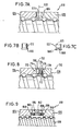
- the bore center line 16 of the receiving bore 14 extends radially to the axis 18 of the threaded spindle 20 and lies in the contact plane 22 of the individual nuts 24 and 26.
- the radial end faces of both individual nuts 24 and 26 abut one another in this plane 22.
- the left single nut 24 carries a fastening flange 28 for connection to a machine element to be moved by the screw drive according to FIG. 1A.
- the diameter d of the locking bolt 12 is slightly smaller than the diameter D of the cylindrical receiving bore 14.
- the diameter d is not noticeably larger than the diameter D in order to rule out that when the locking bolt 12 is inserted, the two individual nuts 24 and 26 in this area also only slightly differ from one another, which leads to a change in the set tensioning or set game and lead to a slight tilt of the axis of one or the other single nut 24 or 26 with respect to the axis 18 of the spindle 20, which would result in increased friction and thus reduced efficiency but also increased wear.
- the locking bolt 12 does not fall out of the receiving bore 14 during operation, in spite of the clearance fit, it is fixed in the receiving bore 14 by means of adhesive or casting resin.
- adhesive or casting resin there would be the danger with a purely cylindrical receiving bore 14 or purely cylindrical locking bolt 12 that this would still come loose.
- the receiving bore 14 is provided with an undercut 30 that is curved outwards and the locking bolt 12 is provided with a circumferential groove 32 at the same height. It is no longer possible for the cast-in locking bolt 12 to fall out, since this would require the casting resin to be deformed in the region between the undercut 30 and the circumferential groove 32.
- the receiving bore 14 Since, as already mentioned, the receiving bore 14 has been made exactly in the contact plane 16 of the two individual nuts 24 and 26, it is axially defined by a substantially semi-cylindrical partial recess 36 in the corresponding end face 34 of the double nut 24 on the left in FIG. 1A and one of these opposite partial recess 38 formed in the opposite end face of the other double nut 26.
- Each partial recess 36 and 38 is provided with a corresponding bulge to form the undercut 30.
- Fig. 1C E are incorporated i nzelmut- ter 24 three such partial recesses 36 in the end face 34, which respective partial recesses are allocated in the single nut 26 so that a total of three lock pins 12 are inserted into the double nut 10.
- Two of the bolts lay diametrically opposite; the third forms 90 ° with the others.
- These three locking bolts ensure that radial forces acting between the individual nuts 24 and 26 are reliably absorbed by the bolts and therefore do not lead to displacement or pivoting of the two individual nuts 24 and 26 relative to one another. It is therefore unnecessary to take separate measures for centering the two individual nuts, for example by using a centering ring. Centering without additional measures can also be achieved with two locking bolts if they are arranged at an angle of 90-120 to the double nut circumference.
- the double nut 110 shown in FIG. 2 differs from the double nut 10 according to FIGS. 1A to 1C only in that one of the two double nuts 124 and 126, namely the double nut 124 on the left in FIG. 2, rests with its fastening flange 128 on the other single nut , so that there is a central fastening of the double nut 110 on the machine part.
- the receiving bore 114 lies exactly in the contact plane 122 of both individual nuts 124 and 126.
- the associated partial recess 136 of the single nut 124 continues radially outward in a diameter-enlarged, also semi-cylindrical groove 140 on the flange 128 .
- This groove 140 can be prefabricated in order to facilitate the production of the receiving bore 114 after the individual nuts 124 and 126 have been tightened.
- a centering ring 242 is provided, which is inserted symmetrically to the contact plane 222 of the single nuts 224 and 226 in an inner circumferential groove 244 of the double nut 210 formed by two internal recesses of the single nuts 224 and 226.
- the centering ring 242 prevents a radial relative movement of the two individual nuts 224 and 226 in the area of the contact plane 222. It is therefore only necessary for the individual nuts to be twisted after a mutual rotation. Securing are ensured, for which a single locking pin 212 is sufficient, which is to be inserted into a receiving bore 214 to be produced in the contact plane 222 after rotation.
- the centering pin 212 is shaped in accordance with the arrangement in FIG. 1B, as is the receiving bore 214, so that the pin 212 glued into the bore 214 holds reliably.
- the locking bolt 312 in the double nut 310 according to FIG. 4 is fixed via an intermediate ring 342, which, like the centering ring 242 according to FIG. 3, is inserted symmetrically to the contact plane 322 of both individual nuts 324 and 326 in cylindrical bores of the individual nuts and therefore radially outwards is covered by the individual nuts.
- the intermediate ring 342 is provided with a screw thread 346 for a corresponding threaded section 348 of the locking bolt 312. As shown in FIG. 4, this threaded section 348 is followed by a larger-diameter cylinder section 350, which fills the receiving bore 314 designed as a through bore.
- a screwdriver slot is provided in the top end face of the locking bolt 312 in FIG. 4; instead, of course, an inner polygon or the like can also be machined into the end face in order to offer an attack for a turning tool for screwing in the screw bolt 312.
- the receiving bore 314 is made in the contact plane 322 at any circumferential point, whereupon the intermediate ring 342 is then rotated until the screw thread 346 comes to lie exactly below the receiving bore 314. This can be accomplished, for example, with the aid of a nail which can engage on the outer circumference of the intermediate ring 342 through the relatively large receiving bore 314.
- both the receiving bore 314 and the screw-in thread 346 are produced.
- the subsequently screwed-in locking pin 312 lies with the shoulder formed between the threaded section 348 and the enlarged-diameter cylinder section 350 directly on the outer circumference of the intermediate ring 342, so that no radial forces are exerted on one or the other single nut by the screwed-in locking pin 314.
- the intermediate ring 342 can simultaneously serve as a centering ring like the ring 242 in FIG. 3, so that a single locking pin 312 is sufficient.
- the locking pin 412 is inserted into a pocket hole-like receiving bore 414 in the contact plane 422 with a clearance fit, again after mutual rotation.
- a locking ring 452 is inserted into an outer circumferential groove 454 of the double nut 410 in the region of the contact plane 422.
- the groove 454 is therefore composed of a step-like twist 456 of the single nut 424 and a twist 458 of the single nut 426.
- the position and width of the assembled groove 454 and the ring width of the securing ring 452 are coordinated with one another in such a way that the ring 452 is axially displaceable between a securing end position shown in solid line in FIG. 5 and a release end position indicated by a broken circumferential line, whereby in the final security position, the receiving bore 414 is covered by the ring 452 and is exposed in the final release position.
- the ring 452 In the release end position, the ring 452 is freely displaceable on the cylindrical shoulder formed by the twist 458; in the final security position, however, there is a tight fit between ring 452 and the corresponding cylindrical section of the Ab rotation 456 of the other individual nut 424, which is achieved by a mild f ügig e increase in the diameter d 1 of this paragraph with respect to the diameter d 2 of the paragraph, the single nut 426th
- the blind hole-like receiving bore 412 must be made in the contact plane 422, whereupon the cylindrical locking bolt 412 is to be inserted, which is then secured by axially displacing the locking ring 452 from its release position into its securing position. If the accuracy requirements are not too high, the locking ring 452 can also serve as a centering ring, so that only a single locking pin 412 is required.
- the double nut 510 shown in FIGS. 6A and 6B differs from the double nut 410 according to FIG. 5 only in that the locking pin 512 inserted into the blind hole-like receiving bore 514 is secured by a circlip 552 which can be displaced in the circumferential direction.
- the securing ring 552 is provided with a circular opening 560 symmetrical to the contact plane 522, the radius r 1 of which is greater than the radius r 2 of the Receiving hole 514. If the circular opening 560 is located exactly above the receiving hole 514, it is freely accessible.
- the locking bolt 512 inserted into the receiving bore 514 can no longer fall out.
- a flat cylindrical recess 562 is drilled radially from the outside on the edge of the twist 558 of the single nut 526, half of which is from corresponding edge of the ring 552 is covered.
- the receiving bore 514 is accordingly made through the circular opening 560, then the pin 512 is inserted and then the ring 552 is rotated until the pin 512 is completely covered.
- the blind bore-like receiving bore 614 which is again symmetrical to the contact plane 622, has an undercut 664 running along the inner circumference in the region of the bore bottom.
- the provided locking pin 612 shown in Fig. 7B has a peripheral bead 666 at one end thereof.
- the locking pin 612 'shown in FIG. 7C is initially purely cylindrical; it receives its circumferential bead ' 666' only when it is pressed against the bottom of the receiving bore 614.
- this bolt end is provided with an inner cone 668 on the end face. Due to this weakening of the material, when the locking bolt 612 'is hammered in, the conical edge is plastically deformed radially outward, forming the circumferential bead 666' filling the undercut 664 '.
- the bead 666 ' is indicated with a broken line, as is the upper end face 670 of the bolt shortened during the upsetting process zens 612 '.
- FIG. 8 A further securing option for the locking bolt is shown in FIG. 8.
- the locking bolt 712 is in turn inserted into a pocket-like receiving bore 714 in the contact plane 722 of the two single nuts 724 and 726 of the double nut 710.
- a radial, continuous screw-in thread 772 is provided in the axial direction opposite the receiving bore 714 for a locking screw 774 designed as a countersunk screw.
- the top of the countersunk head 776 is essentially flush with the outer circumference of the double nut 710.
- the conical underside 778 of the countersunk head 726 when the locking pin 712 is inserted, rests against its conically tapered upper end 780 in FIG. 8, and in this way prevents the locking pin 712 from unintentionally moving radially outward from its receiving bore 714.
- an intermediate ring 842 is provided, similar to the arrangement in FIG. 4, into which a locking bolt can be screwed.
- there are two locking pins namely a locking pin 884 inserted into a separate through hole 882 of the single nut 824 and a locking pin 888 inserted into a through hole 886 of the single nut 826.
- the shape of the two locking pins 884 and 886 corresponds to that of the locking pin 312 Fig. 4, so are in the screwed state with a shoulder on the outer peripheral surface of the intermediate ring 842, so that they can not exert any radial forces on the individual nuts 824 and 826.
- the double nut 810 clamped on the threaded spindle 820 In the manufacture of the double nut 810 clamped on the threaded spindle 820, one can again proceed in such a way that at least one of the receiving bores 882 and 886 and / or at least one of the two screw threads 846 in the middle is ring 842 for the two locking pins 884 and 886 is produced after tightening. Since the intermediate ring 842 can be made of softer material than the individual nuts 824 and 826, it is particularly advantageous if only one of the screw-in threads 846 is subsequently manufactured. For this purpose, one can proceed in such a way that one of the two locking bolts 884 and 888 is inserted into the corresponding receiving bore 882 or 886 and screwed into the prepared internal thread 846 before tightening.
- the individual nuts 824 and 826 can then be clamped on the spindle 820.
- the intermediate ring 842 is drilled through the still free receiving bore 886 or 882 and provided with an internal thread. Then the second locking pin can also be screwed in.
- the receiving bores for the locking bolts can of course all be formed even during the manufacture of the individual parts, namely if, due to particularly precise manufacture, it can be assumed that after turning the two single nuts to cover the Receiving holes or until the partial holes of the individual nuts are covered in the contact plane, the desired preload is set.
- the prefabrication of all receiving bores can also be expedient in those applications in which the preset preload can admissibly vary within a wide range.
Landscapes
- Engineering & Computer Science (AREA)
- General Engineering & Computer Science (AREA)
- Mechanical Engineering (AREA)
- Transmission Devices (AREA)
- Bolts, Nuts, And Washers (AREA)
- Dowels (AREA)
- Piles And Underground Anchors (AREA)
Applications Claiming Priority (2)
| Application Number | Priority Date | Filing Date | Title |
|---|---|---|---|
| DE3207566 | 1982-03-02 | ||
| DE19823207566 DE3207566A1 (de) | 1982-03-02 | 1982-03-02 | Verfahren zur herstellung einer auf einer gewindespindel laufenden doppelmutter |
Publications (2)
| Publication Number | Publication Date |
|---|---|
| EP0087623A1 true EP0087623A1 (fr) | 1983-09-07 |
| EP0087623B1 EP0087623B1 (fr) | 1986-01-02 |
Family
ID=6157156
Family Applications (1)
| Application Number | Title | Priority Date | Filing Date |
|---|---|---|---|
| EP83101197A Expired EP0087623B1 (fr) | 1982-03-02 | 1983-02-08 | Procédé d'assemblage d'une vis-mère double montée sur une broche filetée |
Country Status (4)
| Country | Link |
|---|---|
| US (1) | US4564993A (fr) |
| EP (1) | EP0087623B1 (fr) |
| DE (2) | DE3207566A1 (fr) |
| ES (1) | ES285719Y (fr) |
Families Citing this family (10)
| Publication number | Priority date | Publication date | Assignee | Title |
|---|---|---|---|---|
| US4677869A (en) * | 1985-11-25 | 1987-07-07 | Cincinnati Milacron Inc. | Linear actuator |
| US4864884A (en) * | 1988-08-01 | 1989-09-12 | Dana Corporation | Ball nut and means for attaching a mounting flange thereto |
| US5388475A (en) * | 1993-09-15 | 1995-02-14 | Beaver Precision Products | Ball nut and method of manufacturing same |
| DE19909905B4 (de) * | 1998-08-19 | 2009-07-09 | Viktor Rossmann | Radpanzer bzw. Spähwagenpanzer mit eingebauten seitlichen Sicherheitsstützarmen, die eine Umsturtzgefahr ausschaltet |
| US6698301B2 (en) | 1998-12-29 | 2004-03-02 | Rexroth Star Gmbh | Screw drive with rolling elements, and method of assembly |
| DE19860643A1 (de) | 1998-12-29 | 2000-07-20 | Rexroth Star Gmbh | Wälzkörpergewindetrieb und Verfahren zu dessen Montage |
| DE10006536A1 (de) | 2000-02-15 | 2001-08-23 | Rexroth Star Gmbh | Wälzkörpergewindetrieb und Verfahren zu dessen Montage |
| US9339895B2 (en) * | 2012-06-15 | 2016-05-17 | Anne E. Neale | Universal retrofit kit apparatus and methods thereof |
| US10055964B2 (en) | 2014-09-09 | 2018-08-21 | Torvec, Inc. | Methods and apparatus for monitoring alertness of an individual utilizing a wearable device and providing notification |
| EP3416557B1 (fr) | 2016-02-18 | 2020-07-22 | Curaegis Technologies, Inc. | Système et procédé de prédiction de la vigilance |
Citations (3)
| Publication number | Priority date | Publication date | Assignee | Title |
|---|---|---|---|---|
| US3059494A (en) * | 1960-07-27 | 1962-10-23 | Gen Motors Corp | Preloaded ball bearing screw |
| DE2533996A1 (de) * | 1975-07-30 | 1977-02-17 | T I P Tech Ind Und Produktbera | Kugelrollspindelmuttervorrichtung |
| DE2453635B2 (de) * | 1973-11-15 | 1979-02-22 | Warner Electric Brake & Clutch Co., South Beloit, Ill. (V.St.A.) | Vorgespannte Differentialdoppelmutter |
Family Cites Families (26)
| Publication number | Priority date | Publication date | Assignee | Title |
|---|---|---|---|---|
| US291039A (en) * | 1884-01-01 | Nut-lock | ||
| US1539213A (en) * | 1923-03-29 | 1925-05-26 | Shaw George | Means for locking nuts upon bolts |
| US2198167A (en) * | 1937-08-07 | 1940-04-23 | Hal W Harman | Method for making repairs |
| DE725181C (de) * | 1941-02-06 | 1942-09-16 | Herbert Lindner Fa | Mutter fuer Bewegungsschrauben |
| US2409969A (en) * | 1942-12-15 | 1946-10-22 | William R Williams | Nut lock |
| US2651554A (en) * | 1951-11-30 | 1953-09-08 | Schatz Mfg Company | Antifriction bearing structure |
| DE1255401B (de) * | 1961-07-10 | 1967-11-30 | Pierre Armand Legueu | Mutter fuer Gewindespindeln mit mindestens einer durch Drehen verspannbaren Einstell-Gegenmutter |
| US3170691A (en) * | 1962-07-23 | 1965-02-23 | Frank C Pritchard | Golf club shaft and hosel connector |
| CH431394A (fr) * | 1965-02-05 | 1967-08-31 | Felsa S A | Dispositif d'assemblage de deux pièces de mouvement d'horlogerie |
| US3479897A (en) * | 1967-08-16 | 1969-11-25 | Saginaw Products Corp | Variably preloaded ball nut and screw assembly |
| SE342303B (fr) * | 1968-06-28 | 1972-01-31 | Skf Svenska Kullagerfab Ab | |
| DE1934840A1 (de) * | 1968-07-31 | 1970-02-05 | Marwin Machine Tools Ltd | Leitspindel |
| DE1936546A1 (de) * | 1969-07-18 | 1971-01-28 | Mannesmann Maschinenfabrik A | Vorrichtung zur Erzeugung einer Vorspannung bei Kugelgewindespindeln |
| HU162372B (fr) * | 1969-08-01 | 1973-02-28 | ||
| DE2062521C3 (de) * | 1969-12-19 | 1975-09-18 | Centralne Biuro Konstrukcyjne Obrabiarek, Pruszkow (Polen) | Mutteranordnung für Schraubenwälzgetriebe mit Vorspannungsregelung |
| DE2007380A1 (de) * | 1970-02-11 | 1971-08-26 | Szerszamgepipari Muevek | Kugelumlaufgetriebe |
| DE2051413A1 (de) * | 1970-02-19 | 1971-09-02 | Jenoptik Jena Gmbh | Walzschraubtrieb mit justierbarem axialen Spiel |
| GB1342246A (en) * | 1970-06-10 | 1974-01-03 | Rotax Ltd | Screw and nut mechanism |
| US3820213A (en) * | 1970-08-19 | 1974-06-28 | Brico Eng | Method of making a fuel injector |
| HU167568B (fr) * | 1970-10-09 | 1975-11-28 | ||
| BG18325A1 (fr) * | 1972-10-06 | 1974-10-25 | ||
| DE2360972A1 (de) * | 1973-12-07 | 1975-06-12 | Tos Kurim N P | Differentialvorrichtung zur kontinuierlichen abgrenzung und einstellung des spieles und der vorspannung eines paares von muttern von bewegungsschrauben |
| DE2546109A1 (de) * | 1975-10-15 | 1977-04-28 | Binder Magnete | Anordnung zur einstellung des spiels bei einem spindeltrieb |
| DE7708184U1 (de) * | 1977-03-17 | 1977-07-14 | Raco-Elektro-Maschinen Gmbh, 5830 Schwelm | Kugelgewindetrieb mit zwei gehaeusefreien vorgespannten kugelgewindemuttern |
| DE2940762C2 (de) * | 1979-10-08 | 1982-04-29 | Alois Kuhn GmbH, 7141 Freiberg | Vorspannbare Doppelmutter für Kugelgewindespindeln |
| US4369011A (en) * | 1980-07-31 | 1983-01-18 | Warner Electric Brake & Clutch Company | Preloaded ball screw assembly |
-
1982
- 1982-03-02 DE DE19823207566 patent/DE3207566A1/de not_active Withdrawn
-
1983
- 1983-02-08 DE DE8383101197T patent/DE3361655D1/de not_active Expired
- 1983-02-08 EP EP83101197A patent/EP0087623B1/fr not_active Expired
- 1983-03-01 US US06/471,193 patent/US4564993A/en not_active Expired - Fee Related
- 1983-03-01 ES ES1983285719U patent/ES285719Y/es not_active Expired
Patent Citations (3)
| Publication number | Priority date | Publication date | Assignee | Title |
|---|---|---|---|---|
| US3059494A (en) * | 1960-07-27 | 1962-10-23 | Gen Motors Corp | Preloaded ball bearing screw |
| DE2453635B2 (de) * | 1973-11-15 | 1979-02-22 | Warner Electric Brake & Clutch Co., South Beloit, Ill. (V.St.A.) | Vorgespannte Differentialdoppelmutter |
| DE2533996A1 (de) * | 1975-07-30 | 1977-02-17 | T I P Tech Ind Und Produktbera | Kugelrollspindelmuttervorrichtung |
Non-Patent Citations (2)
| Title |
|---|
| Patent Abstracts of Japan Band 5, Nr. 116, 25. Juli 1981 & JP-A-56-55753 * |
| Patent Abstracts of Japan Band 6, Nr. 201, 13. Oktober 1982 & JP-A-57-107461 * |
Also Published As
| Publication number | Publication date |
|---|---|
| DE3207566A1 (de) | 1983-09-15 |
| DE3361655D1 (en) | 1986-02-13 |
| US4564993A (en) | 1986-01-21 |
| EP0087623B1 (fr) | 1986-01-02 |
| ES285719U (es) | 1987-11-01 |
| ES285719Y (es) | 1988-05-16 |
Similar Documents
| Publication | Publication Date | Title |
|---|---|---|
| DE3872847T2 (de) | Vorrichtung zur sicherstellung der feineinstellung der winkellage eines lenkrades auf einer lenksaeule. | |
| DE3610284C2 (fr) | ||
| DE2453635B2 (de) | Vorgespannte Differentialdoppelmutter | |
| DE19931837B4 (de) | Schraubverbindung für Scharnierteile | |
| DE3831397C2 (de) | Kombination eines Schneidwerkzeugs mit einer Befestigungseinheit zum Befestigen des Schneidwerkzeugs | |
| EP0316832A1 (fr) | Elément de transmission pour installation d'essuyage de véhicules automobiles et son procédé de fabrication | |
| DE9320283U1 (de) | Preßpaßverbindungselement, insbesondere Radbolzen | |
| EP0594872A1 (fr) | Dispositif pour la fabrication de murs et/ou de plafonds, en particulier pour la construction des expositions | |
| EP0164582B1 (fr) | Mandrin pour le montage centré de pièces en rotation | |
| EP0087623B1 (fr) | Procédé d'assemblage d'une vis-mère double montée sur une broche filetée | |
| EP0275441B1 (fr) | Dispositif de serrage | |
| EP0410104B1 (fr) | Outil d'usinage par enlèvement de copeaux | |
| DE3038774C2 (de) | Schraubtrieb mit Doppelmutter | |
| DE3427125C2 (de) | Teilbares Werkzeug für die spanabhebende Bearbeitung | |
| EP0318669A1 (fr) | Accouplement à rondelles élastiques | |
| DE4137978C1 (fr) | ||
| DE2807618A1 (de) | Stimmvorrichtung fuer ein saiteninstrument | |
| DE3717949C2 (fr) | ||
| DE2308287C3 (de) | Vorrichtung zur Drehwinkeleinstellung eines Werkstückes | |
| DE10148473A1 (de) | Kraftschlüssig selbstsichernde Mutter für eine Schraubverbindung | |
| DE69603779T2 (de) | Hochpräzise Zentrierspitze | |
| EP0598289B1 (fr) | Boulon de centrage pour la fixation, le centrage et/ou le positionnement des éléments avec des trous de centrage | |
| DE10212671A1 (de) | Kegelradausgleichsgetriebe | |
| DE7901702U1 (de) | Schraubenkopf | |
| DE4020354C2 (fr) |
Legal Events
| Date | Code | Title | Description |
|---|---|---|---|
| PUAI | Public reference made under article 153(3) epc to a published international application that has entered the european phase |
Free format text: ORIGINAL CODE: 0009012 |
|
| AK | Designated contracting states |
Designated state(s): CH DE FR GB IT LI |
|
| 17P | Request for examination filed |
Effective date: 19831006 |
|
| GRAA | (expected) grant |
Free format text: ORIGINAL CODE: 0009210 |
|
| AK | Designated contracting states |
Designated state(s): CH DE FR GB IT LI |
|
| ITF | It: translation for a ep patent filed | ||
| REF | Corresponds to: |
Ref document number: 3361655 Country of ref document: DE Date of ref document: 19860213 |
|
| ET | Fr: translation filed | ||
| PLBI | Opposition filed |
Free format text: ORIGINAL CODE: 0009260 |
|
| 26 | Opposition filed |
Opponent name: SKF GMBH Effective date: 19860930 |
|
| RAP2 | Party data changed (patent owner data changed or rights of a patent transferred) |
Owner name: DEUTSCHE STAR GMBH |
|
| REG | Reference to a national code |
Ref country code: CH Ref legal event code: PFA Free format text: DEUTSCHE STAR GMBH |
|
| REG | Reference to a national code |
Ref country code: FR Ref legal event code: CD |
|
| PLBN | Opposition rejected |
Free format text: ORIGINAL CODE: 0009273 |
|
| STAA | Information on the status of an ep patent application or granted ep patent |
Free format text: STATUS: OPPOSITION REJECTED |
|
| 27O | Opposition rejected |
Effective date: 19871218 |
|
| ITTA | It: last paid annual fee | ||
| PGFP | Annual fee paid to national office [announced via postgrant information from national office to epo] |
Ref country code: GB Payment date: 19960115 Year of fee payment: 14 |
|
| PGFP | Annual fee paid to national office [announced via postgrant information from national office to epo] |
Ref country code: CH Payment date: 19960122 Year of fee payment: 14 |
|
| PGFP | Annual fee paid to national office [announced via postgrant information from national office to epo] |
Ref country code: FR Payment date: 19960126 Year of fee payment: 14 |
|
| PG25 | Lapsed in a contracting state [announced via postgrant information from national office to epo] |
Ref country code: GB Effective date: 19970208 |
|
| PG25 | Lapsed in a contracting state [announced via postgrant information from national office to epo] |
Ref country code: LI Effective date: 19970228 Ref country code: CH Effective date: 19970228 |
|
| GBPC | Gb: european patent ceased through non-payment of renewal fee |
Effective date: 19970208 |
|
| REG | Reference to a national code |
Ref country code: CH Ref legal event code: PL |
|
| PG25 | Lapsed in a contracting state [announced via postgrant information from national office to epo] |
Ref country code: FR Effective date: 19971030 |
|
| REG | Reference to a national code |
Ref country code: FR Ref legal event code: ST |
|
| PGFP | Annual fee paid to national office [announced via postgrant information from national office to epo] |
Ref country code: DE Payment date: 20010125 Year of fee payment: 19 |
|
| PG25 | Lapsed in a contracting state [announced via postgrant information from national office to epo] |
Ref country code: DE Free format text: LAPSE BECAUSE OF NON-PAYMENT OF DUE FEES Effective date: 20020903 |